EP1061532A1 - Poudre magnétique et aimant isotropique à liant - Google Patents
Poudre magnétique et aimant isotropique à liant Download PDFInfo
- Publication number
- EP1061532A1 EP1061532A1 EP00112388A EP00112388A EP1061532A1 EP 1061532 A1 EP1061532 A1 EP 1061532A1 EP 00112388 A EP00112388 A EP 00112388A EP 00112388 A EP00112388 A EP 00112388A EP 1061532 A1 EP1061532 A1 EP 1061532A1
- Authority
- EP
- European Patent Office
- Prior art keywords
- magnetic powder
- magnetic
- bonded magnet
- magnet
- isotropic
- Prior art date
- Legal status (The legal status is an assumption and is not a legal conclusion. Google has not performed a legal analysis and makes no representation as to the accuracy of the status listed.)
- Granted
Links
- 239000006247 magnetic powder Substances 0.000 title claims abstract description 134
- 230000002427 irreversible effect Effects 0.000 claims abstract description 44
- 229910045601 alloy Inorganic materials 0.000 claims abstract description 26
- 239000000956 alloy Substances 0.000 claims abstract description 26
- 239000002131 composite material Substances 0.000 claims abstract description 21
- 229920005989 resin Polymers 0.000 claims abstract description 20
- 239000011347 resin Substances 0.000 claims abstract description 20
- 238000010586 diagram Methods 0.000 claims abstract description 19
- 229910052761 rare earth metal Inorganic materials 0.000 claims abstract description 19
- 238000000465 moulding Methods 0.000 claims abstract description 17
- 230000005347 demagnetization Effects 0.000 claims abstract description 16
- 239000000203 mixture Substances 0.000 claims abstract description 13
- 238000002156 mixing Methods 0.000 claims abstract description 4
- 230000005415 magnetization Effects 0.000 claims description 34
- 238000004519 manufacturing process Methods 0.000 claims description 27
- XEEYBQQBJWHFJM-UHFFFAOYSA-N iron Substances [Fe] XEEYBQQBJWHFJM-UHFFFAOYSA-N 0.000 claims description 22
- 238000010438 heat treatment Methods 0.000 claims description 21
- 239000002114 nanocomposite Substances 0.000 claims description 14
- 229910052751 metal Inorganic materials 0.000 claims description 13
- 239000002184 metal Substances 0.000 claims description 13
- 238000001816 cooling Methods 0.000 claims description 12
- 150000002910 rare earth metals Chemical group 0.000 claims description 11
- 238000010298 pulverizing process Methods 0.000 claims description 9
- 229910052742 iron Inorganic materials 0.000 claims description 7
- 238000010791 quenching Methods 0.000 claims description 7
- 230000000171 quenching effect Effects 0.000 claims description 7
- 229910052802 copper Inorganic materials 0.000 claims description 5
- 229910052804 chromium Inorganic materials 0.000 claims description 4
- 229910052758 niobium Inorganic materials 0.000 claims description 4
- 229910052710 silicon Inorganic materials 0.000 claims description 4
- 229910052715 tantalum Inorganic materials 0.000 claims description 4
- 229910052726 zirconium Inorganic materials 0.000 claims description 4
- 229910052732 germanium Inorganic materials 0.000 claims description 3
- 229910052735 hafnium Inorganic materials 0.000 claims description 3
- 229910052750 molybdenum Inorganic materials 0.000 claims description 3
- 229910052698 phosphorus Inorganic materials 0.000 claims description 3
- 229910052709 silver Inorganic materials 0.000 claims description 3
- 229910052720 vanadium Inorganic materials 0.000 claims description 3
- 229910052725 zinc Inorganic materials 0.000 claims description 3
- 230000004907 flux Effects 0.000 abstract description 61
- 238000000034 method Methods 0.000 description 28
- 238000005260 corrosion Methods 0.000 description 24
- 230000007797 corrosion Effects 0.000 description 23
- XKRFYHLGVUSROY-UHFFFAOYSA-N Argon Chemical compound [Ar] XKRFYHLGVUSROY-UHFFFAOYSA-N 0.000 description 16
- 230000000694 effects Effects 0.000 description 16
- 239000012298 atmosphere Substances 0.000 description 13
- 239000000463 material Substances 0.000 description 12
- JEIPFZHSYJVQDO-UHFFFAOYSA-N iron(III) oxide Inorganic materials O=[Fe]O[Fe]=O JEIPFZHSYJVQDO-UHFFFAOYSA-N 0.000 description 11
- 238000011156 evaluation Methods 0.000 description 9
- IJGRMHOSHXDMSA-UHFFFAOYSA-N Atomic nitrogen Chemical compound N#N IJGRMHOSHXDMSA-UHFFFAOYSA-N 0.000 description 8
- 229910052786 argon Inorganic materials 0.000 description 8
- 239000007789 gas Substances 0.000 description 8
- 238000001746 injection moulding Methods 0.000 description 8
- 238000007792 addition Methods 0.000 description 7
- 238000001125 extrusion Methods 0.000 description 7
- 239000000843 powder Substances 0.000 description 7
- 230000008901 benefit Effects 0.000 description 6
- 238000000748 compression moulding Methods 0.000 description 6
- 238000006467 substitution reaction Methods 0.000 description 6
- 229920005992 thermoplastic resin Polymers 0.000 description 6
- -1 Co) in particular) Substances 0.000 description 5
- 150000001875 compounds Chemical class 0.000 description 5
- 239000003822 epoxy resin Substances 0.000 description 5
- 239000001307 helium Substances 0.000 description 5
- 229910052734 helium Inorganic materials 0.000 description 5
- SWQJXJOGLNCZEY-UHFFFAOYSA-N helium atom Chemical compound [He] SWQJXJOGLNCZEY-UHFFFAOYSA-N 0.000 description 5
- 230000006872 improvement Effects 0.000 description 5
- 230000001965 increasing effect Effects 0.000 description 5
- 239000011261 inert gas Substances 0.000 description 5
- 238000005259 measurement Methods 0.000 description 5
- 238000005551 mechanical alloying Methods 0.000 description 5
- 230000003647 oxidation Effects 0.000 description 5
- 238000007254 oxidation reaction Methods 0.000 description 5
- 229920000647 polyepoxide Polymers 0.000 description 5
- 230000002441 reversible effect Effects 0.000 description 5
- 239000002344 surface layer Substances 0.000 description 5
- 229920001187 thermosetting polymer Polymers 0.000 description 5
- 229910052782 aluminium Inorganic materials 0.000 description 4
- 239000011230 binding agent Substances 0.000 description 4
- 239000010949 copper Substances 0.000 description 4
- 229910052757 nitrogen Inorganic materials 0.000 description 4
- 239000004734 Polyphenylene sulfide Substances 0.000 description 3
- 230000015572 biosynthetic process Effects 0.000 description 3
- 230000006866 deterioration Effects 0.000 description 3
- 230000003993 interaction Effects 0.000 description 3
- 239000002075 main ingredient Substances 0.000 description 3
- 230000005405 multipole Effects 0.000 description 3
- 229920002647 polyamide Polymers 0.000 description 3
- 229920000728 polyester Polymers 0.000 description 3
- 229920000069 polyphenylene sulfide Polymers 0.000 description 3
- 239000010453 quartz Substances 0.000 description 3
- VYPSYNLAJGMNEJ-UHFFFAOYSA-N silicon dioxide Inorganic materials O=[Si]=O VYPSYNLAJGMNEJ-UHFFFAOYSA-N 0.000 description 3
- 238000004804 winding Methods 0.000 description 3
- KXGFMDJXCMQABM-UHFFFAOYSA-N 2-methoxy-6-methylphenol Chemical compound [CH]OC1=CC=CC([CH])=C1O KXGFMDJXCMQABM-UHFFFAOYSA-N 0.000 description 2
- OAKJQQAXSVQMHS-UHFFFAOYSA-N Hydrazine Chemical compound NN OAKJQQAXSVQMHS-UHFFFAOYSA-N 0.000 description 2
- 229920000106 Liquid crystal polymer Polymers 0.000 description 2
- 239000004977 Liquid-crystal polymers (LCPs) Substances 0.000 description 2
- UFWIBTONFRDIAS-UHFFFAOYSA-N Naphthalene Chemical compound C1=CC=CC2=CC=CC=C21 UFWIBTONFRDIAS-UHFFFAOYSA-N 0.000 description 2
- 229910052779 Neodymium Inorganic materials 0.000 description 2
- 239000004677 Nylon Substances 0.000 description 2
- 229920000305 Nylon 6,10 Polymers 0.000 description 2
- 229920000572 Nylon 6/12 Polymers 0.000 description 2
- 239000004952 Polyamide Substances 0.000 description 2
- 239000004721 Polyphenylene oxide Substances 0.000 description 2
- 239000003963 antioxidant agent Substances 0.000 description 2
- 230000003078 antioxidant effect Effects 0.000 description 2
- 229910052796 boron Inorganic materials 0.000 description 2
- 230000003028 elevating effect Effects 0.000 description 2
- 230000002708 enhancing effect Effects 0.000 description 2
- 238000004898 kneading Methods 0.000 description 2
- 229920001778 nylon Polymers 0.000 description 2
- 229920001568 phenolic resin Polymers 0.000 description 2
- 239000005011 phenolic resin Substances 0.000 description 2
- 229920001721 polyimide Polymers 0.000 description 2
- 239000009719 polyimide resin Substances 0.000 description 2
- 229920000098 polyolefin Polymers 0.000 description 2
- 238000005096 rolling process Methods 0.000 description 2
- 229920002050 silicone resin Polymers 0.000 description 2
- 239000000126 substance Substances 0.000 description 2
- 238000012360 testing method Methods 0.000 description 2
- 229930185605 Bisphenol Natural products 0.000 description 1
- ZOXJGFHDIHLPTG-UHFFFAOYSA-N Boron Chemical compound [B] ZOXJGFHDIHLPTG-UHFFFAOYSA-N 0.000 description 1
- 229910052684 Cerium Inorganic materials 0.000 description 1
- RYGMFSIKBFXOCR-UHFFFAOYSA-N Copper Chemical compound [Cu] RYGMFSIKBFXOCR-UHFFFAOYSA-N 0.000 description 1
- 229910000881 Cu alloy Inorganic materials 0.000 description 1
- 229910052692 Dysprosium Inorganic materials 0.000 description 1
- 229910052691 Erbium Inorganic materials 0.000 description 1
- 229910052693 Europium Inorganic materials 0.000 description 1
- 229910052688 Gadolinium Inorganic materials 0.000 description 1
- 229910052689 Holmium Inorganic materials 0.000 description 1
- JHWNWJKBPDFINM-UHFFFAOYSA-N Laurolactam Chemical compound O=C1CCCCCCCCCCCN1 JHWNWJKBPDFINM-UHFFFAOYSA-N 0.000 description 1
- 229910052765 Lutetium Inorganic materials 0.000 description 1
- 239000004640 Melamine resin Substances 0.000 description 1
- 229920000877 Melamine resin Polymers 0.000 description 1
- 229910001122 Mischmetal Inorganic materials 0.000 description 1
- 229920000571 Nylon 11 Polymers 0.000 description 1
- 229920000299 Nylon 12 Polymers 0.000 description 1
- 229920003189 Nylon 4,6 Polymers 0.000 description 1
- 229920002292 Nylon 6 Polymers 0.000 description 1
- 229920002302 Nylon 6,6 Polymers 0.000 description 1
- 239000004696 Poly ether ether ketone Substances 0.000 description 1
- 229930182556 Polyacetal Natural products 0.000 description 1
- 239000004697 Polyetherimide Substances 0.000 description 1
- 239000004698 Polyethylene Substances 0.000 description 1
- 239000004743 Polypropylene Substances 0.000 description 1
- 229910052777 Praseodymium Inorganic materials 0.000 description 1
- 229910052772 Samarium Inorganic materials 0.000 description 1
- 229910052771 Terbium Inorganic materials 0.000 description 1
- 229910052775 Thulium Inorganic materials 0.000 description 1
- 229920001807 Urea-formaldehyde Polymers 0.000 description 1
- 238000002441 X-ray diffraction Methods 0.000 description 1
- 229910052769 Ytterbium Inorganic materials 0.000 description 1
- 230000001133 acceleration Effects 0.000 description 1
- 230000009471 action Effects 0.000 description 1
- 239000000654 additive Substances 0.000 description 1
- 230000000996 additive effect Effects 0.000 description 1
- WYTGDNHDOZPMIW-RCBQFDQVSA-N alstonine Natural products C1=CC2=C3C=CC=CC3=NC2=C2N1C[C@H]1[C@H](C)OC=C(C(=O)OC)[C@H]1C2 WYTGDNHDOZPMIW-RCBQFDQVSA-N 0.000 description 1
- XAGFODPZIPBFFR-UHFFFAOYSA-N aluminium Chemical compound [Al] XAGFODPZIPBFFR-UHFFFAOYSA-N 0.000 description 1
- 239000012300 argon atmosphere Substances 0.000 description 1
- 125000003118 aryl group Chemical group 0.000 description 1
- 230000005540 biological transmission Effects 0.000 description 1
- IISBACLAFKSPIT-UHFFFAOYSA-N bisphenol A Chemical compound C=1C=C(O)C=CC=1C(C)(C)C1=CC=C(O)C=C1 IISBACLAFKSPIT-UHFFFAOYSA-N 0.000 description 1
- 239000011248 coating agent Substances 0.000 description 1
- 238000000576 coating method Methods 0.000 description 1
- 229910017052 cobalt Inorganic materials 0.000 description 1
- 239000010941 cobalt Substances 0.000 description 1
- GUTLYIVDDKVIGB-UHFFFAOYSA-N cobalt atom Chemical compound [Co] GUTLYIVDDKVIGB-UHFFFAOYSA-N 0.000 description 1
- 230000000052 comparative effect Effects 0.000 description 1
- 229920001577 copolymer Polymers 0.000 description 1
- 238000007334 copolymerization reaction Methods 0.000 description 1
- 230000008878 coupling Effects 0.000 description 1
- 238000010168 coupling process Methods 0.000 description 1
- 238000005859 coupling reaction Methods 0.000 description 1
- 239000013078 crystal Substances 0.000 description 1
- 239000006185 dispersion Substances 0.000 description 1
- 238000009826 distribution Methods 0.000 description 1
- 239000005038 ethylene vinyl acetate Substances 0.000 description 1
- 238000002474 experimental method Methods 0.000 description 1
- 238000000605 extraction Methods 0.000 description 1
- 230000006870 function Effects 0.000 description 1
- 238000009689 gas atomisation Methods 0.000 description 1
- 230000005484 gravity Effects 0.000 description 1
- LNEPOXFFQSENCJ-UHFFFAOYSA-N haloperidol Chemical compound C1CC(O)(C=2C=CC(Cl)=CC=2)CCN1CCCC(=O)C1=CC=C(F)C=C1 LNEPOXFFQSENCJ-UHFFFAOYSA-N 0.000 description 1
- 238000000265 homogenisation Methods 0.000 description 1
- 238000010348 incorporation Methods 0.000 description 1
- 230000006698 induction Effects 0.000 description 1
- 239000004615 ingredient Substances 0.000 description 1
- 229910052746 lanthanum Inorganic materials 0.000 description 1
- 239000007788 liquid Substances 0.000 description 1
- 239000000314 lubricant Substances 0.000 description 1
- 239000000696 magnetic material Substances 0.000 description 1
- 239000000155 melt Substances 0.000 description 1
- 239000007769 metal material Substances 0.000 description 1
- 239000013081 microcrystal Substances 0.000 description 1
- 229920003986 novolac Polymers 0.000 description 1
- 230000035699 permeability Effects 0.000 description 1
- 229920001200 poly(ethylene-vinyl acetate) Polymers 0.000 description 1
- 229920006111 poly(hexamethylene terephthalamide) Polymers 0.000 description 1
- 229920003229 poly(methyl methacrylate) Polymers 0.000 description 1
- 229920001707 polybutylene terephthalate Polymers 0.000 description 1
- 239000004417 polycarbonate Substances 0.000 description 1
- 229920000515 polycarbonate Polymers 0.000 description 1
- 229920000570 polyether Polymers 0.000 description 1
- 229920002530 polyetherether ketone Polymers 0.000 description 1
- 229920001601 polyetherimide Polymers 0.000 description 1
- 229920000573 polyethylene Polymers 0.000 description 1
- 229920000642 polymer Polymers 0.000 description 1
- 239000004926 polymethyl methacrylate Substances 0.000 description 1
- 229920006324 polyoxymethylene Polymers 0.000 description 1
- 229920006380 polyphenylene oxide Polymers 0.000 description 1
- 229920001155 polypropylene Polymers 0.000 description 1
- 229920005749 polyurethane resin Polymers 0.000 description 1
- 230000002265 prevention Effects 0.000 description 1
- 238000001953 recrystallisation Methods 0.000 description 1
- 230000009467 reduction Effects 0.000 description 1
- 238000011160 research Methods 0.000 description 1
- 230000000452 restraining effect Effects 0.000 description 1
- 239000007787 solid Substances 0.000 description 1
- 238000007711 solidification Methods 0.000 description 1
- 230000008023 solidification Effects 0.000 description 1
- 229920006259 thermoplastic polyimide Polymers 0.000 description 1
- 229910052723 transition metal Inorganic materials 0.000 description 1
- 229920006337 unsaturated polyester resin Polymers 0.000 description 1
- XLYOFNOQVPJJNP-UHFFFAOYSA-N water Substances O XLYOFNOQVPJJNP-UHFFFAOYSA-N 0.000 description 1
- 229910052727 yttrium Inorganic materials 0.000 description 1
- 229910000859 α-Fe Inorganic materials 0.000 description 1
Images




Classifications
-
- B—PERFORMING OPERATIONS; TRANSPORTING
- B82—NANOTECHNOLOGY
- B82Y—SPECIFIC USES OR APPLICATIONS OF NANOSTRUCTURES; MEASUREMENT OR ANALYSIS OF NANOSTRUCTURES; MANUFACTURE OR TREATMENT OF NANOSTRUCTURES
- B82Y25/00—Nanomagnetism, e.g. magnetoimpedance, anisotropic magnetoresistance, giant magnetoresistance or tunneling magnetoresistance
-
- H—ELECTRICITY
- H01—ELECTRIC ELEMENTS
- H01F—MAGNETS; INDUCTANCES; TRANSFORMERS; SELECTION OF MATERIALS FOR THEIR MAGNETIC PROPERTIES
- H01F1/00—Magnets or magnetic bodies characterised by the magnetic materials therefor; Selection of materials for their magnetic properties
- H01F1/01—Magnets or magnetic bodies characterised by the magnetic materials therefor; Selection of materials for their magnetic properties of inorganic materials
- H01F1/03—Magnets or magnetic bodies characterised by the magnetic materials therefor; Selection of materials for their magnetic properties of inorganic materials characterised by their coercivity
- H01F1/032—Magnets or magnetic bodies characterised by the magnetic materials therefor; Selection of materials for their magnetic properties of inorganic materials characterised by their coercivity of hard-magnetic materials
- H01F1/04—Magnets or magnetic bodies characterised by the magnetic materials therefor; Selection of materials for their magnetic properties of inorganic materials characterised by their coercivity of hard-magnetic materials metals or alloys
- H01F1/047—Alloys characterised by their composition
- H01F1/053—Alloys characterised by their composition containing rare earth metals
- H01F1/055—Alloys characterised by their composition containing rare earth metals and magnetic transition metals, e.g. SmCo5
- H01F1/057—Alloys characterised by their composition containing rare earth metals and magnetic transition metals, e.g. SmCo5 and IIIa elements, e.g. Nd2Fe14B
- H01F1/0579—Alloys characterised by their composition containing rare earth metals and magnetic transition metals, e.g. SmCo5 and IIIa elements, e.g. Nd2Fe14B with exchange spin coupling between hard and soft nanophases, e.g. nanocomposite spring magnets
Definitions
- the present invention relates to magnetic powder and an isotropic bonded magnet produced using the magnetic powder.
- a magnet For reduction in size of motors, it is desirable that a magnet has a high magnetic flux density (with the actual permeance) when it is used in the motor.
- Factors for determining the magnetic flux density of a bonded magnet include magnetic performance (that is, magnetization) of the magnetic powder and the content (that is, compositional ratio) of the magnetic powder contained in the bonded magnet. Accordingly, when the magnetic performance (magnetization) of the magnetic powder itself is not sufficiently high, a desired magnetic flux density cannot be obtained unless the content of the magnetic powder in the bonded magnet is raised to an extremely high level.
- the isotropic bonded magnets which are made using MQP-B powder manufactured by MQI Corp. as the rare-earth magnetic powder thereof.
- the isotropic bonded magnets are superior to the anisotropic bonded magnets in the following respect; namely, in the manufacture of the bonded magnet, the manufacturing process can be simplified because no magnetic field orientation is required, and as a result, the rise in the manufacturing cost can be restrained.
- the conventional isotropic bonded magnets represented by those manufactured using MQP-B powder have the following disadvantages.
- the present invention is directed to magnetic powder composed of an alloy composition represented by R x (Fe 1-y Co y ) 100-x-z-w B z Al w (where R is at least one kind of rare-earth element, x is 8.1 - 9.4at%, y is 0 - 0.30, z is 4.6 - 6.8at%, and w is 0.02- 1.5at%), the magnetic powder being constituted from a composite structure having a soft magnetic phase and a hard magnetic phase, wherein the magnetic powder has characteristics in which, when the magnetic powder is formed into an isotropic bonded magnet by mixing with a binding resin and then molding it, the irreversible susceptibility ( ⁇ irr ) which is measured by using an intersectioning point of a demagnetization curve in the J-H diagram representing the magnetic characteristics at the room temperature and a straight line which passes the origin in the J-H diagram and has a gradient (J/H) of -3.8 x 10- 6 H/m as a starting
- each of the magnetic powders has the composite structure having a soft magnetic phase and a hard magnetic phase and contains a predetermined amount of Al, they have high magnetizability and exhibit excellent magnetic characteristics so that intrinsic coercive force and rectangularity thereof are especially improved.
- the absolute value of the irreversible flux loss is small and excellent heat resisting property (heat stability) can be obtained.
- the magnetizability of the magnet according to this invention is excellent, it is possible to magnetize a magnet with a lower magnetizing field.
- multipolar magnetization or the like can be accomplished easily and surely, and further a high magnetic flux density can be obtained.
- the present invention is adapted to the manufacturing method such as the extrusion molding method or the injection molding method by which molding at high density is difficult as compared with the compression molding method, and the effects described in the above can also be realized in the bonded magnet manufactured by these molding methods. Accordingly, various molding method can be selectively used and thereby the degree of selection of shapes for the bonded magnet can be expanded.
- the composite structure is a nanocomposite structure.
- said R comprises rare-earth elements mainly containing Nd and/or Pr.
- said R includes Pr and its ratio with respect to the total mass of said R is 5 - 75%. When the ratio lies in this range, it is possible to improve the coercivity and the rectangularity by hardly causing a drop in the remanent magnetic flux density.
- said R includes Dy and its ratio with respect to the total mass of said R is equal to or less than 14%.
- the ratio lies in this range, the coercivity can be improved without causing marked drop in the remanent magnetic flux density, and an improvement of the heat resisting property is also possible.
- the magnetic powder is obtained by quenching the alloy of a molten state.
- the magnetic powder is obtained by pulverizing a quenched ribbon of the alloy which is manufactured by using a cooling roll.
- the magnetic powder is subjected to a heat treatment for at least once during the manufacturing process or after its manufacture.
- the average grain size of the magnetic powder lies in the range of 0.5 - 150 ⁇ m.
- the present invention is also directed to an isotropic rare-earth bonded magnet, which is formed by binding the magnetic powder as set forth in the above with a binding resin.
- the present invention is also directed to an isotropic rare-earth bonded magnet formed by binding magnetic powder containing Al with a binding resin, wherein the isotropic rare-earth bonded magnet is characterized in that the irreversible susceptibility ( ⁇ irr ) which is measured by using an intersectioning point of a demagnetization curve in the J-H diagram representing the magnetic characteristics at the room temperature and a straight line which passes the origin in the J-H diagram and has a gradient (J/H) of -3.8 x 10- 6 H/m as a starting point is less than 5.0 x 10- 7 H/m, and the intrinsic coercive force (H CJ ) of the magnet at the room temperature is in the range of 406 - 717 kA/m.
- ⁇ irr irreversible susceptibility
- said magnetic powder is formed of R-TM-B-Al based alloy (where R is at least one rear- earth element and TM is a transit metal containing Iron as a major component thereof.
- the magnetic powder includes at least one element which is selected from the group comprising Cu, Si, Ga, Ti, V, Ta, Zr, Nb, Mo, Hf, Ag, Zn, P, Ge and Cr.
- the content of the element is equal to or less than 3at%.
- the magnetic powder is constituted from a composite structure having a soft magnetic phase and a hard magnetic phase.
- the isotropic bonded magnet is to be subjected to multipolar magnetization or is already subjected to multipolar magnetization. In this case, it is also preferred that the isotropic bonded magnet is used for a motor.
- a magnet having high magnetic flux density is practically required in order to reduce the size of motors or other electrical devices.
- factors that determine the magnetic flux density are the magnetic performance (magnetization, in particular) of magnetic powder and the content (compositional ratio) of the magnetic powder contained in the bonded magnet.
- the magnetic performance (magnetization) of the magnetic powder itself is not so high, a desired magnetic flux density cannot be obtained unless the content of the magnetic powder in the bonded magnet is increased to an extremely high level.
- MQP-B powder made by MQI Corp. which is now being widely used can not provide sufficient magnetic flux density depending on its use.
- it is required to increase the content of the magnetic powder in the bonded magnet, that is, it is required to increase the magnetic flux density.
- this leads to the lack of reliability in the corrosion resistance property, heat resisting property and mechanical strength thereof and the like.
- there is a problem in that the obtained magnet has a poor magnetizability due to its high coercivity.
- the magnetic powder and the isotropic bonded magnet (isotropic rear-earth bonded magnet) according to this invention can obtain a sufficient magnetic flux density and an adequate coercive force.
- the magnetic powder and the isotropic bonded magnet can obtain a sufficient magnetic flux density and an adequate coercive force.
- the magnetic powder of the present invention may be formed so as to constitute a composite structure having a hard magnetic phase and a soft magnetic phase.
- the MQP-B powder made by MQI Corp. is a single phase structure of a hard magnetic phase
- the magnetic powder of the present invention is a nanocomposite structure which also has a soft magnetic phase having a high magnetization. Accordingly, it has an advantage that the total magnetization of the system as a whole is high. Further, the recoil permeability of the bonded magnet becomes high, there is an advantage that, even after a reverse magnetic field is applied, the demagnetizing factor remains small.
- the magnetic powder according to this invention has alloy compositions represented by R x (Fe 1-y Co y ) 100-x-z-w B z Al w (R is at least one kind of rare-earth elements, x is 8.1 - 9.4at%, y is 0 - 0.30, z is 4.6 - 6.8at%, and w is 0.02 - 1.5at%).
- rare-earth metals R include Y, La, Ce, Pr, Nd, Pm, Sm, Eu, Gd, Tb, Dy, Ho, Er, Tm, Yb, Lu, and a misch metal.
- R may include one kind or two or more kinds of these elements.
- the content of R is set at 8.1 - 9.4at%.
- the content of R is less than 8.1at%, sufficient coercive force cannot be obtained, and addition of Al enhances the coercive force only to a small extent.
- the content of R exceeds 9.4at%, sufficient magnetic flux density fails to be obtained because of the drop in the magnetization potential.
- R includes the rare-earth elements Nd and/or Pr as the principal ingredient.
- these rare-earth elements enhance the saturation magnetization of the hard magnetic phase which constitutes the composite structure (especially, nanocomposite structure) the magnetic powder, and are effective in realizing satisfactory coercive force as a magnet.
- R includes Pr, and its ratio to the totality of R is 5 - 75%, and more preferably 10 - 60%. This is because when the ratio lies in this range, it is possible to improve the coercivity and the rectangularity by hardly causing a drop in the remanent magnetic flux density.
- R includes Dy and its ratio to the totality of R is equal to or less than 14%.
- the ratio lies in this range, the coercivity can be improved without causing marked drop in the remanent magnetic flux density, and the heat resisting property is also improved.
- Co is a transition metal element having properties similar to Fe.
- Co that is by substituting a part of Fe by Co
- the Curie temperature is elevated and the temperature characteristic of the powder is improved.
- the substitution ratio of Fe by Co exceeds 0.30, both of the coercive force and the magnetic flux density tend to fall off.
- the range of 0.05 - 0.20 of the substitution ratio of Fe by Co is more preferable since in this range not only the temperature characteristic (heat resisting property and heat stability) of the magnetic powder but also the magnetic flux density thereof are improved.
- a part of Fe or Co may be substituted by Ni.
- Boron (B) is an element which is important for obtaining high magnetic characteristics, and its content is set at 4.6 - 6.8at%.
- the content of B is less than 4.6at%, the rectangularity of the magnetic power is deteriorated.
- the content of B exceeds 6.8at%, the nonmagnetic phase increase and the magnetic flux density drops sharply.
- Aluminum (Al) is an element which is advantageous for improving the coercive force, and the effect of improvement of the coercive force is conspicuous when its content lies in the range of 0.02 - 1.5at%.
- the rectangularity and the maximum magnetic energy product are improved in this range in accompanying with the improvement in the coercive force, and the corrosion resistance property becomes also satisfactory.
- the content of R is less than 8.1at%, these effects due to addition of Al are very small as mentioned above.
- the content of Al exceeds 1.5at%, the drop in the magnetization is conspicuous, which makes it difficult to obtain a high magnetic density flux, thereby lowering the coercive force.
- Al itself is a known substance.
- the feature of this invention can be found in the incorporation of a minute amount or trace amount of Al, and addition of Al in the amount exceeding 1.5at% gives rather an inverse effect and therefore it is not the intent of this invention.
- the preferred range of the content of Al is 0.02 - 1.5at% as described above.
- the upper limit of the range is 1.2at% and it is the most preferable that the upper limit is 0.8at%.
- At least one other element selected from the group comprising Cu, Si, Ga, Ti, V, Ta, Zr, Nb, Mo, Hf, Ag, Zn, P, Ge and Cr may be contained as needed.
- the element belonging to Q it is preferable that the content thereof should be less than 3at%, and it is more preferable that the content thereof lies in the range of 0.2 - 3at%, and it is the most preferable that the content thereof lies in the range of 0.5 - 2at%.
- the addition of the element belonging to Q makes it possible to exhibit inherent effect of the kind of the element.
- the addition of Cu, Si, Ga, V, Ta, Zr, Cr or Nb exhibits an effect of improving corrosion resistance property.
- the addition of Si exhibits the effects (1) to (3) described above in addition to the effect of improving the corrosion resistance property.
- the magnetic material of the present invention has a composite structure having a soft magnetic phase and a hard magnetic phase.
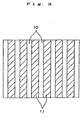
- a soft magnetic phase 10 and a hard magnetic phase 11 exist in a pattern (model) as shown in, for example, Fig. 1, Fig. 2 or Fig. 3, where the thickness or grain diameter of the respective phases is on the order of nanometers (for example, 1 - 100nm). Further, the soft magnetic phase 10 and the hard magnetic phase 11 are arranged adjacent to each other (this also includes the case where these phases are adjacent through grain boundary phase), which makes it possible to perform magnetic exchange interaction therebetween.
- the average grain diameter size is preferably 5 to 50nm and more preferably 10 to 40nm.
- the average crystal grain size (diameter) is less than the lower limit value, the influence of the magnetic exchange interaction becomes too strong and thereby magnetic inversion is likely to occur, which may result in the case where the coercive force is deteriorated.
- the average crystalline grain size exceeds the upper limit value, the crystalline grain size becomes large while the influence of the magnetic exchange interaction between crystalline grains is weakened, thus leading to the case that the magnetic flux density, coercive force and rectangularity and maximum energy product may be deteriorated.
- Fig. 1 to Fig. 3 are only specific examples, and are not limited thereto.
- the soft magnetic phase 10 and the hard magnetic phase 11 in Fig. 2 are interchanged.
- the magnetization of the soft magnetic phase readily changes its orientation by the action of an external magnetic field. Therefore, when it coexists with the hardmagnetic phase, the magnetization curve for the entire system shows a stepped "serpentine curve" in the second quadrant of the J-H diagram.
- the soft magnetic phase has a sufficiently small size of less than several tens of nm, magnetization of the soft magnetic body is sufficiently strongly constrained through the coupling with the magnetization of the surrounding hard magnetic body, so that the entire system exhibits functions like a hard magnetic body.
- a magnet having such a composite structure has mainly the following five features.
- the hard magnetic phase and the soft magnetic phase are composed of, for example, respectively by the following.
- the hard magnetic phase R 2 TM 14 B system (where, TM is Fe or Fe and Co), or R 2 TM 14 BAl system (or R 2 TM 14 BQ system, or R 2 TM 14 BalQ system).
- the soft magnetic phase TM ( ⁇ -Fe or ⁇ -(Fe, Co) in particular), or an alloy of TM and Al (or an alloy of TM and Q or an alloy of TM, Al and Q).
- the magnetic powders according to this invention it is preferable that they are manufactured by quenching a molten alloy, and more preferable that they are manufactured by pulverizing a quenched ribbon obtained by quenching and solidifying the molten metal of the alloy.
- An example of such a method will be described in the following.
- Fig. 4 is a perspective view showing an example of the configuration of an apparatus (quenched ribbon manufacturing apparatus) for manufacturing a magnet material by the quenching method using a single roll
- Fig. 5 is a sectional side view showing the situation in the vicinity of colliding section of the molten metal with a cooling roll in the apparatus shown in Fig. 4.
- a quenched ribbon manufacturing apparatus 1 is provided with a cylindrical body 2 capable of storing the magnet material, and a cooling roll 5 which rotates in the direction of an arrow 9A in the figure relative to the cylindrical body 2.
- a nozzle (orifice) 3 which injects the molten metal of the magnet material alloy is formed at the lower end of the cylindrical body 2.
- a heating coil 4 is arranged on the outer periphery of the cylindrical body 2 in the vicinity of the nozzle 3, and the magnet material in the cylindrical body 2 is melted by inductively heating the interior of the cylindrical body 2 through application of, for example, a high frequency wave to the coil 4.
- the cooling roll 5 is constructed from a base part 51 and a surface layer 52 which forms a circumferential surface 53 of the cooling roll 5.
- the base part 51 may be formed either integrally with the surface layer 52 using the same material, or formed using a material different from that of the surface layer 52.
- the material of the base part 51 it is preferable that it is a metallic material with high heat conductivity such as copper or a copper alloy in order to be able to dissipate heat of the surface layer 52 as quickly as possible.
- the surface layer 52 is constituted of a material with heat conductivity equal to or lower than that of the base part 51.
- the quenched ribbon manufacturing apparatus 1 is installed in a chamber (not shown), and is operated preferably under the condition where the interior of the chamber is filled with an inert or other kind of gas.
- the gas is an inert gas such as argon, helium, nitrogen or the like.
- the magnet material (alloy) is placed in the cylindrical body 2 and melted by heating with the coil 4, and the molten metal 6 is discharged from the nozzle 3. Then, as shown in Fig. 5. the molten metal 6 collides with the circumferential surface 53 of the cooling roll 5, and after the formation of a puddle 7, the molten metal 6 is cooled down rapidly to be solidified while dragged along the circumferential surface 53 of the rotating cooling roll 5, thereby forming the quenched ribbon 8 continuously or intermittently. Roll surface 81 of the quenched ribbon 8 thus formed is soon released from the circumferential surface 53, and proceeds in the direction of an arrow 9B in Fig. 4. The solidification interface 71 of the molten metal is indicated by a broken line In Fig. 5.
- the optimum range of the circumferential velocity of the cooling roll 5 depends upon the composition of the molten alloy, the wettability of the circumferential surface 53 with respect to the molten metal 6, and the like. However, for the enhancement of the magnetic characteristics, a velocity in the range of 1 to 60m/s is normally preferable, and 5 to 40m/s is more preferable. If the circumferential velocity of the cooling roll 5 is too small, the thickness t of the quenched ribbon 8 is too large depending upon the volume flow rate (volume of the molten metal discharged per unit time), and the diameter of the crystalline grains tends to increase. On the contrary, if the circumferential velocity is too large, amorphous structure becomes dominant. Further, enhancement of the magnetic characteristics can be expected in neither case even if a heat treatment is given in the later stage.
- quenched ribbon 8 may be subjected to a heat treatment for the purpose of, for example, acceleration of recrystallization of the amorphous structure and homogenization of the structure.
- the conditions of this heat treatment may be, for example, a heating in the range of 400 to 900°C for 0.5 to 300 min.
- this heat treatment is preferable to be performed in a vacuum or under a reduced pressure (for example, in the range of 1 x 10 -1 to 1 x 10 -6 Torr), or in a nonoxidizing atmosphere of an inert gas such as nitrogen, argon, helium or the like.
- the quenched ribbon (thin ribbon-like magnet material) 8 obtained as in the above has a microcrystalline structure or a structure in which microcrystals are included in an amorphous structure, and exhibits excellent magnetic characteristics.
- the magnetic powder of this invention is obtained by pulverizing the quenched ribbon 8.
- the pulverizing method of the quenched ribbon is not particularly limited, and various kinds of pulverizing or crushing apparatus such as ball mill, vibration mill, jet mill, and pin mill may be employed.
- pulverization may be performed under vacuum or reduced pressure (for example, under a low pressure of 1 x 10 -1 to 1 x 10 -6 Torr), or in a nonoxidizing atmosphere of an inert gas such as nitrogen, argon, helium, or the like.
- the average, grain size of the magnetic powder is not particularly limited. However, for magnetic powder to be used for manufacturing isotropic bonded magnets described later, by considering prevention of oxidation of the magnetic powder and of deterioration in the magnetic characteristics due to pulverization, it is preferable to choose the range of 0.5 to 150 ⁇ m, more preferably the range of 1.0 to 65 ⁇ m, and still more preferably the range of 5 to 55 ⁇ m.
- the bonded magnet In order to obtain a better moldability of the bonded magnet, it is preferable to give a certain degree of dispersion to the grain size distribution of the magnetic powder. By so doing, it is possible to reduce the porosity of the bonded magnet obtained. As a result, it is possible to raise the density and the mechanical strength of the bonded magnet assuming the same content of the magnetic powder in the bonded magnet, thereby enabling to further improve the magnetic characteristics.
- the obtained magnetic powder may be subjected to a heat treatment for the purpose of, for example, removing the influence of stress introduced by the pulverization and controlling the crystalline grain size.
- the conditions of the heat treatment are, for example, heating at a temperature in the range of 350 to 850°C for 0.5 to 300 min.
- the heat treatment in a vacuum or under a reduced pressure (for example, in the range of 1 x 10 -1 to 1 x 10 -6 Torr), or in a nonoxidizing atmosphere of an inert gas such as nitrogen, argon, and helium.
- a vacuum or under a reduced pressure for example, in the range of 1 x 10 -1 to 1 x 10 -6 Torr
- an inert gas such as nitrogen, argon, and helium.
- the obtained magnetic powder has a satisfactory bindability with the binding resin (wettability of the binding resin), so that the bonded magnet has a high mechanical strength and excellent thermal stability (heat resisting property) and corrosion resistance property. Consequently, it can be concluded that the magnetic powder is suitable for the manufacture of the bonded magnet.
- the quenching method is described in terms of the single roll method, but the twin roll method may also be employed. Besides, other methods such as the atomizing method which uses gas atomization, the rotating disk method, the melt extraction method, and the mechanical alloying method (MA) may also be employed. Since such a quenching method can refine the metallic structure (crystalline grains), it is effective for enhancing the magnet characteristics, especially the coercivity or the like, of the bonded magnet.
- bonded magnets (hereinafter, referred to simply also as “bonded magnets”) according to this invention will be described.
- the bonded magnets of this invention is formed by binding the above described magnetic powder using a binding resin.
- thermoplastic resin either of a thermoplastic resin or a thermosetting resin may be employed.
- thermoplastic resin for example, a polyamid (example: nylon 6, nylon 46, nylon 66, nylon 610, nylon 612, nylon 11, nylon 12, nylon 6-12, nylon 6-66, nylon 6T and nylon 9T); a thermoplastic polyimide; a liquid crystal polymer such as an aromatic polyester; a poly phenylene oxide; a poly phenylene sulfide; a polyolefin such as a polyethylene, a polypropylene and an ethylene-vinyl acetate copolymer; a modified polyolefin; a polycarbonate; a poly methyl methacrylate; a polyester such as a poly ethylen terephthalate and a poly butylene terephthalate; a polyether; a polyether ether ketone; a polyetherimide; a polyacetal, or the like; and a copolymer, a blended body, and a polymer alloy having these as main ingredients, or the like, may be mentioned
- thermoplastic resins also have an excellent kneadability with the magnetic powder.
- thermoplastic resins provide an advantage in that a wide range of selection can be made. For example, it is possible to provide a thermoplastic resin having a good moldability or to provide a thermoplastic resin having good heat resisting property and mechanical strength by appropriately selecting their kinds, copolymerization or the like.
- thermosetting resin various kinds of epoxy resins of bisphenol type, novolak type, and naphthalene-based, a phenolic resin, a urea resin, a melamine resin, a polyester (or an unsaturated polyester) resin, a polyimide resin, a silicone resin, a polyurethane resin, or the like, for example, may be mentioned, and one kind or a mixture of two or more kinds of these may be employed.
- thermosetting resins an epoxy resin, a phenolic resin, a polyimide resin, or a silicone resin is preferable from the viewpoint of their special excellence in the moldability, high mechanical strength, and high heat resisting property, and an epoxy resin is especially preferable.
- thermosetting resins also have an excellent kneadability with the magnetic powder and homogeneity in kneading.
- the unhardened thermosetting resin to be used may be either in liquid state or in solid (powdery) state at room temperature.
- a bonded magnet according to this invention described in the above may be manufactured, for example, as in the following.
- a bonded magnet composite compound which contains the magnetic powder, a binder resin, and an additive (antioxidant, lubricant, or the like) as needed, is prepared.
- the prepared compound is formed into a desired magnet form in a space free from magnetic field by a molding method such as compression molding (press molding), extrusion molding, or injection molding.
- a molding method such as compression molding (press molding), extrusion molding, or injection molding.
- the binding resin used is a thermosetting type
- the obtained green compact is hardened by heating or the like after molding.
- the extrusion molding and the injection molding have advantages in that the latitude of shape selection is broad, the productivity is high, and the like.
- these molding methods require to ensure a sufficiently high fluidity of the compound in the molding machine in order to obtain satisfactory moldability. For this reason, in these methods it is not possible to increase the content of the magnetic powder, namely, to make the bonded magnet having high density, as compared with the case of the compression molding method. In this invention, however, it is possible to obtain a high magnetic flux density as will be described later, so that excellent magnetic characteristics can be obtained even without making the bonded magnet high density.
- This advantage of the present invention can also be extended even in the case where bonded magnets are manufactured by the extrusion molding method or the injection molding method.
- the content of the magnetic powder in the bonded magnet is not particularly limited, and it is normally determined by considering the compatibility of the molding method and moldability, and high magnetic characteristics. More specifically, it is preferable to be in the range of 75 - 99wt%, and more preferably in the range of 85 - 97.5wt%.
- the content of the magnetic powder is preferable to be in the range of 90 - 99wt%, and more preferably in the range of 93 - 98.5wt%.
- the content of the magnetic powder is preferable to be in the range of 75 - 98wt%, and more preferably in the range of 85 - 97wt%.
- the density ⁇ of the bonded magnet is determined by factors such as the specific gravity of the magnetic powder contained in the magnet and the content of the magnetic powder, and porosity of the bonded magnet and the like.
- the density ⁇ is not particularly limited, but it is preferable to be in the range of 5.3 - 6.6g/cm 3 , and more preferably in the range of 5.5 - 6.4g/cm 3 .
- the molded bonded magnet since the magnetic flux density and the coercive force of the magnetic powder are high and the magnetic powder has a relatively larger coercive force, the molded bonded magnet provides excellent magnetic characteristics (especially, high maximum magnetic energy product) even when the content of the magnetic powder is relatively low. In this regard, it goes without saying that it is possible to obtain the excellent magnetic characteristics in the case where the content of the magnetic powder is high.
- the shape, dimensions, and the like of the bonded magnet manufactured according to this invention are not particularly limited.
- the shape all shapes such as columnar, prism-like, cylindrical (ring-shaped), circular, plate-like, curved plate-like, and the like are acceptable.
- the dimensions all sizes starting from large-sized one to ultraminuaturized one are acceptable.
- the present invention is particularly advantageous in miniaturization and ultraminiaturization of the bonded magnet.
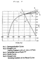
- the bonded magnet of this invention as described in the above has magnetic characteristics in which the irreversible susceptibility ( ⁇ irr ) which is measured by using an intersectioning point of a demagnetization curve in the J-H diagram (that is, coordinate where the longitudinal axis represents magnetization (J) and the horizontal axis represents magnetic field (H)) representing the magnetic characteristics at the room temperature and a straight line which passes the origin in the J-H diagram and has a gradient (J/H) of -3.8 x 10- 6 H/m as a starting point is less than 5.0 x 10- 7 H/m, and the intrinsic coercive force (H CJ ) of the magnet at the room temperature is in the range of 406 - 717 kA/m.
- ⁇ irr the irreversible susceptibility
- H CJ intrinsic coercive force
- the irreversible susceptibility ( ⁇ irr ) is the parameter which is represented by the following formula (unit is Henry/m, which is represented by H/m in this specification), wherein a gradient of a tangential line of the demagnetization curve at a certain point P on the demagnetization curve in the J-H diagram is defined by differential susceptibility ( ⁇ dif ) and a gradient of a recoil curve when the recoil curve from the point P is drawn with the demagnetization field being once reduced (that is, a gradient connecting the both ends of the, recoil curve) is defined by reversible susceptibility( ⁇ rev ).
- Irreversible Susceptibility ( ⁇ irr ) differential susceptibility ( ⁇ dif ) - reversible susceptibility( ⁇ rev )
- the point P is defined as an intersectioning point of the demagnetization curve and the straight line y which passes the origin in the J-H diagram and has a gradient (J/H) of -3.8 x 10- 6 H/m.
- the irreversible susceptibility ( ⁇ irr ) represents the changing ratio of the magnetization, which is not returned even if the absolute value thereof is reduced once after demagnetization is applied, with respect to the magnetic field. Accordingly, by restraining the irreversible susceptibility ( ⁇ irr ) to a relatively small value, it is possible to improve heat stability of the bonded magnet and especially to reduce the absolute value of the irreversible flux loss.
- the irreversible flux loss obtained when the bonded magnet is being left in the atmosphere of 100°C for one hour and then the temperature is lowered into room temperature is equal to or less than 5% in its absolute value, which means that practically satisfactory heat resisting property (in particular when used in motors or the like), that is heat stability can be obtained.
- the irreversible susceptibility ( ⁇ irr ) at the room temperature is defined as 5.0 x 10- 7 H/m is described above. However, it is preferred that the value of the irreversible susceptibility ( ⁇ irr ) is as smaller as possible. Therefore, in the present invention, it is preferable that the irreversible susceptibility ( ⁇ irr ) is equal to or less than 4.5 x 10- 7 H/m, and it is more preferable that the irreversible susceptibility ( ⁇ irr ) is equal to or less than 4.0 x 10- 7 H/m.
- the intrinsic coercive force (H CJ ) of the bonded magnet at room temperature is 406 to 717kA/m, and 435 to 677kA/m is more preferable.
- the intrinsic coercive force (H CJ ) exceeds the above upper limit value, magnetizability is deteriorated.
- the intrinsic coercive force (H CJ ) is lower than the lower limit value, demagnetization occurs conspicuously when a reverse magnetic field is applied depending upon the usage of the motor and the beat resisting property at a high temperature is deteriorated.
- H CJ intrinsic coercive force
- the maximum magnetic energy product (BH) max of the bonded magnet of the present invention is not particularly limited to the specific value. However, in the present invention, 87 to 125 kJ/m 3 is preferable and 100 to 125 kJ/m 3 is more preferable.
- Magnetic powders with alloy compositions Nd 8.7 Fe 77.2-w Co 8.5 B 5.6 Al w that is, various types of magnetic powders in which the content w of Al is changed variously) were obtained by the method described below.
- each of the materials Nd, Fe, Co, B, and Al was weighed to cast a mother alloy ingot, and a sample of about 15g was cut out from the ingot.
- a quenched ribbon manufacturing apparatus 1 as shown in Fig. 4 and Fig. 5 was prepared, and the sample was placed in a quartz tube 2 having a nozzle (circular orifice) 3 at the bottom. After evacuating the interior of a chamber in which the quenched ribbon manufacturing apparatus 1 is housed, an inert gas (Ar gas and helium gas) was introduced to obtain an atmosphere with desired temperature and pressure.
- Ar gas and helium gas Ar gas and helium gas
- the ingot sample in the quartz tube 2 was melted by high frequency induction heating, the circumferential velocity and the jetting pressure (difference between the inner pressure of the quartz tube 2 and the pressure of the atmosphere) were adjusted to 20m/s and 40kPa, respectively. Under the state, the molten metal was jetted against the circumferential surface 53 of the cooling roll 5, to obtain a quenched ribbon (average thickness of about 30 ⁇ m, and average width of about 1.6 mm).
- the quenched ribbon was then coarsely crushed, and the powder was subjected to a heat treatment in an argon atmosphere at 680°C for 300sec. In this way, the various types of magnetic powders each having different contents w of Al were obtained.
- the respective magnetic powder was subjected to X-ray diffraction using Cu-K ⁇ line at the diffraction angle of 20° - 60° . From the thus obtained diffraction pattern, the presence of diffracted peaks of a hard magnetic phase, Nd 2 (Fe.Co) 14 B 1 phase, and a soft magnetic phase, ⁇ -(Fe,Co) phase, were confirmed. Further, from the observation result using a transmission electron microscope (TEN), the formation of a nanocomposite structure was confirmed in each magnetic powder.
- TEN transmission electron microscope
- each magnetic powder was ground by a granulator in an argon gas atmosphere to obtain magnetic powder having average grain size of 60 ⁇ m.
- a composite (compound) for bonded magnet was prepared by mixing the respective magnetic powder with an epoxy resin and a small amount of hydrazine antioxidant and then kneading them.
- each of the thus obtained compounds was crushed to be granular. Then, the granular substance was weighed and filled into a die of a press machine, and a molded body was obtained by compression molding (in the absence of a magnetic field) the sample at a pressure of 7ton/cm 2 .
- the epoxy resin was cured by heating at a temperature of 150°C (that is subjected to cure treatment) and a columnar isotropic bonded magnet with diameter 10mm ⁇ and height 7mm was obtained.
- the content of the magnetic powder in the respective bonded magnets was 97.0wt% and the magnetic density of the respective bonded magnets was about 6.21 Mg/m 3 .
- the heat resisting property (heat stability) of the respective bonded magnets (each having the column shape having diameter of 10mm and height of 7mm) was examined.
- the heat resisting property was obtained by measuring the irreversible flux loss (ratio of flux loss) obtained when the bonded magnet was being left in the atmosphere of 100°C for one hour and then the temperature was lowered to the room temperature, and then it was evaluated. The results thereof are shown in the attached Table 1. In this connection, it is to be noted that smaller absolute value of the irreversible flux loss (ratio of flux loss) means more excellent heat resisting property (heat stability).
- the magnetizability thereof was measured by changing the magnetized magnetic field variously.
- the ratio of magnetization was represented using the ratio with respect to the remanent magnetic flux under the magnetized magnetic filed of 4.8MA/m, where the remanent magnetic flux is represented by 100%.
- the size of the magnetized magnetic filed of each of the bonded magnets when the ratio of magnetization is 90% was shown in the attached Table 1. In this Table, smaller value means more excellent magnetizability.
- the isotropic bonded magnets formed of the magnetic powders in which the content w of Al is 0.02 to 1.5at% and the irreversible susceptibility ( ⁇ irr ) is equal to or less than 5.0 x 10- 7 H/m exhibit excellent magnetic characteristics (remanent magnetic flux density, intrinsic coercive force and maximum magnetic energy product) and have small absolute value of the irreversible susceptibility ( ⁇ irr ), so that the heat resisting property of these magnets is high and the magnetizability thereof is excellent.
- the isotropic bonded magnets of the comparative examples which were composed from magnetic powders containing no Al or containing 2.0at% of Al (more than the upper limit of the present invention) have poor magnetic characteristics. Further, the absolute value of the irreversible flux loss is large and the heat stability is low.
- bonded magnets having high performance and high reliability (especially, heat resisting property). In particular, these characteristics are exhibited when the bonded magnets are used in motors.
- Example 2 magnetic powders were obtained from the respective quenched ribbons, and then cylindrical (ring-shaped) isotropic bonded magnets having outer diameter of 20mm, inner diameter of 18mm and height of 7mm were manufactured.
- the content of the magnetic powder in each of the bonded magnets was about 96.8wt%.
- the density of each of the bonded magnets was about 6.18Mg/m 3 .
- these bonded magnets were respectively subjected to multi-pole magnetization of 12 poles, and using each bonded magnet as a magnet for a rotor, a DC brush-less motor was assembled. Then, each of the DC motors was rotated at 4000rpm to measure a back electromotive force generated in the coil winding thereof. As a result, it has been confirmed that a sufficiently high voltage could be obtained in each of the motors and these motors have a high performance.
- bonded magnets same as those of Example 1 were manufactured excepting that the various types of the magnetic powder having the different substitution ratio y of Pr described above are used.
- the heat resisting property (heat stability) and the magnetizability of each of the thus manufactured bonded magnets was measured in the same way as Example 1, and the measurement results thereof were evaluated. The results thereof are shown in the attached Table 2.
- each of the isotropic bonded magnets has excellent magnetic characteristics (remanent magnetic flux density Br, intrinsic coercive force (H CJ ), and maximum magnetic energy product (BH) max ) and the absolute value of the irreversible flux loss thereof is small, so that the heat resisting property (heat stability) is high and the magnetizability thereof is excellent.
- the intrinsic coercive force and the maximum magnetic energy product are improved while the excellent heat resisting property and magnetizability are maintained, by substituting a part of Nd with a predetermined amount of Pr (that is, an amount equal to or less than 75% with respect to the whole amount of R).
- bonded magnets having high performance and high reliability (especially, heat resisting property). In particular, these characteristics are exhibited when these bonded magnets are used in motors.
- Example 2 magnetic powders were obtained from the respective quenched ribbons, and then cylindrical (ring-shaped) isotropic bonded magnets having outer diameter of 20mm, inner diameter of 18mm and height of 7mm were manufactured.
- the content of the magnetic powder in each of the bonded magnets was about 96.8wt%.
- the density of each of the bonded magnets was about 6.20Mg/m 3 .
- these bonded magnets were respectively subjected to multi-pole magnetization of 12 poles, and using each bonded magnet as a magnet for a rotor, a DC brush-less motor was assembled. Then, each of the DC motors was rotated at 4000rpm to measure a back electromotive force generated in the coil winding thereof. As a result, it has been confirmed that a sufficiently high voltage can be obtained in each of the motors, and these motors have a high performance.
- bonded magnets same as those of Example 1 were manufactured excepting that the various types of the magnetic powder having the, different substitution ratio 1-z of Dy described above are used.
- each of the isotropic bonded magnets has excellent magnetic characteristics (remanent magnetic flux density Br, intrinsic coercive force (H CJ ), and maximum magnetic energy product (BH) max ) and the absolute value of the irreversible flux loss thereof is small, so that the heat resisting property (heat stability) is high and the magnetizability thereof is excellent.
- the intrinsic coercive force and the maximum magnetic energy product were improved while the excellent heat resisting property and magnetizability are maintained, by adding a predetermined amount of Dy (equal to or less than 14% with respect to the whole amount of R).
- bonded magnets having high performance and high reliability (especially, heat resisting property). In particular, these characteristics are exhibited when these bonded magnets are used in motors.
- Example 2 magnetic powders were obtained from the respective quenched ribbons, and then cylindrical (ring-shaped) isotropic bonded magnets having outer diameter of 20mm, inner diameter of 18mm and height of 7mm were manufactured using the magnetic powders.
- the content of the magnetic powder in each of the bonded magnets was about 96.9wt%. Further, the density of each of the bonded magnets was about 6.19Mg/m 3 .
- these bonded magnets were respectively subjected to multi-pole magnetization of 12 poles, and using each bonded magnet as a magnet for a rotor, a DC brush-less motor was assembled. Then, each of the DC motors was rotated at 4000rpm to measure a back electromotive force generated in the coil winding thereof. As a result, it has been confirmed that a sufficiently high voltage can be obtained in each of the motors, and these motors have a high performance.
- bonded magnets same as those of Example 1 were manufactured excepting that various types of the magnetic powder having the different content v of Si are used.
- the heat resisting property (heat stability) and the magnetizability of each of the bonded magnets were measured in the same way as Example 1. Further, using the method described below, the heat resisting property (heat stability) and the magetizability thereof were measured, and evaluated. The results thereof are shown in the attached Table 4.
- the corrosion resistance property of the respective bonded magnet was evaluated by a dewing test (dew formation test). This rust examination was carried out by alternately placing each of the magnetic powders in the atmosphere at a temperature of 30°C and a RH of 50% for 15minutes or in the atmosphere at a temperature of 80°C and a RH of 95%RH for fifteen minutes, and this was repeated for 24 times. Thereafter, the surface of each magnet was observed by a microscope and the degree of the generation of the rust was evaluated from the viewpoints of the following four steps.
- the bonded magnets (ten bonded magnets for each) were inmersed into a bath containing water at a temperature of 60°C and a RH of 95%, and then the average time required until any rust is generated in each of the bonded magnets was examined. The results thereof were evaluated from the viewpoints of the following four steps.
- each of the isotropic bonded magnets exhibits excellent magnetic characteristics (remanent magnetic flux density, intrinsic coercive force and maximum magnetic energy product) and heat resisting property (heat stability), and the magnetizability of the respective magnets is good.
- the bonded magnets composed from the magnetic powder in which a predetermined amount of Si (0.1 to 3at%) is contained have an improved corrosion resistance property in the magnetic powder itself as well as the bonded magnet formed therefrom as compared with the bonded magnets containing no Si. Therefore, it is possible to omit or simplify corrosion preventing treatment such as application of anti-corrosion coating on the surfaces of the bonded magnets when they are actually used.
- bonded magnets having high performance and high reliability (especially, high heat resisting property and corrosion resistance property).
- high performance can be exhibited.
- Isotropic bonded magnets were manufactured in the same manner as that used in Examples 1-4 excepting that the bonded magnets were produced using the extrusion molding.
- polyamide Nylon 610
- the content of the magnetic powder in the respective bonded magnets was about 95.5wt% and the magnetic density thereof was about 5.85Mg/m 3 .
- Isotropic bonded magnets of the present invention were manufactured in the same manner as that used in Examples 1-4 excepting that the bonded magnets were produced using the injection molding.
- poly phenylene sulfide was used in the respective bonded magnets as a binder.
- the content of the magnetic powder in the respective bonded magnets was about 94.1wt% and the magnetic density thereof was about 5.63Mg/m 3 .
- each of the magnetic powders has the composite structure having a soft magnetic phase and a hard magnetic phase and contains a predetermined amount of Al, they have high magnetizability and exhibit excellent magnetic characteristics so that intrinsic coercive force and rectangularity thereof are especially improved.
- the absolute value of the irreversible flux loss is small and excellent heat resisting property (heat stability) can be obtained.
- the magnetizability of the magnet according to this invention is excellent, it is possible to magnetize a magnet with a lower magnetizing field.
- multipolar magnetization or the like can be accomplished easily and surely, and further a high magnetic flux density can be obtained.
- the present invention is adapted to the manufacturing method such as the extrusion molding method or the injection molding method by which molding at high density is difficult as compared with the compression molding method, and the effects described in the above can also be realized in the bonded magnet manufactured by these molding methods. Accordingly, various molding method can be selectively used and thereby the degree of selection of shaped for the bonded magnet can be expanded.
Landscapes
- Chemical & Material Sciences (AREA)
- Engineering & Computer Science (AREA)
- Crystallography & Structural Chemistry (AREA)
- Nanotechnology (AREA)
- Inorganic Chemistry (AREA)
- Composite Materials (AREA)
- Power Engineering (AREA)
- Hard Magnetic Materials (AREA)
Applications Claiming Priority (4)
| Application Number | Priority Date | Filing Date | Title |
|---|---|---|---|
| JP16523499 | 1999-06-11 | ||
| JP16523499 | 1999-06-11 | ||
| JP20791099A JP3275882B2 (ja) | 1999-07-22 | 1999-07-22 | 磁石粉末および等方性ボンド磁石 |
| JP20791099 | 1999-07-22 |
Publications (2)
| Publication Number | Publication Date |
|---|---|
| EP1061532A1 true EP1061532A1 (fr) | 2000-12-20 |
| EP1061532B1 EP1061532B1 (fr) | 2006-11-22 |
Family
ID=26490045
Family Applications (1)
| Application Number | Title | Priority Date | Filing Date |
|---|---|---|---|
| EP20000112388 Expired - Lifetime EP1061532B1 (fr) | 1999-06-11 | 2000-06-09 | Poudre magnétique et aimant isotropique à liant |
Country Status (2)
| Country | Link |
|---|---|
| EP (1) | EP1061532B1 (fr) |
| DE (1) | DE60031914T8 (fr) |
Cited By (14)
| Publication number | Priority date | Publication date | Assignee | Title |
|---|---|---|---|---|
| EP1115124A3 (fr) * | 2000-01-06 | 2002-05-02 | Seiko Epson Corporation | Poudre magnétique et aimant à liant isotropique |
| EP1115125A3 (fr) * | 2000-01-06 | 2002-05-02 | Seiko Epson Corporation | Poudre magnétique et aimant à liant isotropique |
| EP1115123A3 (fr) * | 2000-01-06 | 2002-05-02 | Seiko Epson Corporation | Poudre magnétique et aimant à liant isotropique |
| US6521054B2 (en) | 2000-01-14 | 2003-02-18 | Seiko Epson Corporation | Magnetic powder and isotropic bonded magnet |
| US6527875B2 (en) | 2000-01-07 | 2003-03-04 | Seiko Epson Corporation | Magnetic powder and isotropic bonded magnet |
| US6551418B2 (en) | 2000-01-07 | 2003-04-22 | Seiko Epson Corporation | Magnetic powder and isotropic bonded magnet |
| US6706124B2 (en) | 2000-05-24 | 2004-03-16 | Sumitomo Special Metals Co., Ltd. | Permanent magnet including multiple ferromagnetic phases and method of producing the magnet |
| US6790296B2 (en) | 2000-11-13 | 2004-09-14 | Neomax Co., Ltd. | Nanocomposite magnet and method for producing same |
| US7004228B2 (en) | 2000-10-06 | 2006-02-28 | Santoku Corporation | Process for producing, through strip casting, raw alloy for nanocomposite type permanent magnet |
| US7138070B2 (en) * | 2000-05-30 | 2006-11-21 | Seiko Epson Corporation | Magnetic material manufacturing method, ribbon-shaped magnetic materials, powdered magnetic material and bonded magnets |
| US7208097B2 (en) | 2001-05-15 | 2007-04-24 | Neomax Co., Ltd. | Iron-based rare earth alloy nanocomposite magnet and method for producing the same |
| US7217328B2 (en) | 2000-11-13 | 2007-05-15 | Neomax Co., Ltd. | Compound for rare-earth bonded magnet and bonded magnet using the compound |
| US7261781B2 (en) | 2001-11-22 | 2007-08-28 | Neomax Co., Ltd. | Nanocomposite magnet |
| US7507302B2 (en) | 2001-07-31 | 2009-03-24 | Hitachi Metals, Ltd. | Method for producing nanocomposite magnet using atomizing method |
Citations (3)
| Publication number | Priority date | Publication date | Assignee | Title |
|---|---|---|---|---|
| EP0195219A2 (fr) * | 1985-02-25 | 1986-09-24 | Ovonic Synthetic Materials Company, Inc. | Matériau trempé magnétique permanent |
| EP0657899A1 (fr) * | 1993-12-10 | 1995-06-14 | Sumitomo Special Metals Company Limited | Poudres à base de fer à aimantation permanente pour aimants à liant, et aimants de cela |
| JPH10259459A (ja) * | 1997-01-14 | 1998-09-29 | Mitsubishi Materials Corp | 希土類磁石粉末製造用原料合金およびこの原料合金を用いた希土類磁石粉末の製造方法 |
-
2000
- 2000-06-09 DE DE2000631914 patent/DE60031914T8/de active Active
- 2000-06-09 EP EP20000112388 patent/EP1061532B1/fr not_active Expired - Lifetime
Patent Citations (3)
| Publication number | Priority date | Publication date | Assignee | Title |
|---|---|---|---|---|
| EP0195219A2 (fr) * | 1985-02-25 | 1986-09-24 | Ovonic Synthetic Materials Company, Inc. | Matériau trempé magnétique permanent |
| EP0657899A1 (fr) * | 1993-12-10 | 1995-06-14 | Sumitomo Special Metals Company Limited | Poudres à base de fer à aimantation permanente pour aimants à liant, et aimants de cela |
| JPH10259459A (ja) * | 1997-01-14 | 1998-09-29 | Mitsubishi Materials Corp | 希土類磁石粉末製造用原料合金およびこの原料合金を用いた希土類磁石粉末の製造方法 |
Non-Patent Citations (4)
| Title |
|---|
| CHANG W C ET AL: "MAGNETIC PROPERTIES ENHANCEMENT OF ALPHA-FE/ND2FE14B-TYPE NANOCOMPOSITES BY CO SUBSTITUTION", JOURNAL OF APPLIED PHYSICS,US,AMERICAN INSTITUTE OF PHYSICS. NEW YORK, vol. 83, no. 4, 15 February 1998 (1998-02-15), pages 2147 - 2151, XP000769698, ISSN: 0021-8979 * |
| GOLL D ET AL: "Magnetic and microstructural properties of nanocrystalline exchange coupled PrFeB permanent magnets", JOURNAL OF MAGNETISM AND MAGNETIC MATERIALS,NL,ELSEVIER SCIENCE PUBLISHERS, AMSTERDAM, vol. 185, no. 1, 20 May 1998 (1998-05-20), pages 49 - 60, XP004128133, ISSN: 0304-8853 * |
| GRIEB B ET AL: "PHASE RELATIONS AND MAGNETIC PROPERTIES OF NEW PHASES IN THE FE-ND-AL AND FE-ND-C SYSTEMS AND THEIR INFLUENCE ON MAGNETS", IEEE TRANSACTIONS ON MAGNETICS,US,IEEE INC. NEW YORK, vol. 26, no. 5, 1 September 1990 (1990-09-01), pages 1367 - 1369, XP000150239, ISSN: 0018-9464 * |
| PATENT ABSTRACTS OF JAPAN vol. 1998, no. 14 31 December 1998 (1998-12-31) * |
Cited By (19)
| Publication number | Priority date | Publication date | Assignee | Title |
|---|---|---|---|---|
| EP1115124A3 (fr) * | 2000-01-06 | 2002-05-02 | Seiko Epson Corporation | Poudre magnétique et aimant à liant isotropique |
| EP1115125A3 (fr) * | 2000-01-06 | 2002-05-02 | Seiko Epson Corporation | Poudre magnétique et aimant à liant isotropique |
| EP1115123A3 (fr) * | 2000-01-06 | 2002-05-02 | Seiko Epson Corporation | Poudre magnétique et aimant à liant isotropique |
| US6855265B2 (en) | 2000-01-07 | 2005-02-15 | Seiko Epson Corporation | Magnetic powder and isotropic bonded magnet |
| US6551418B2 (en) | 2000-01-07 | 2003-04-22 | Seiko Epson Corporation | Magnetic powder and isotropic bonded magnet |
| US6527875B2 (en) | 2000-01-07 | 2003-03-04 | Seiko Epson Corporation | Magnetic powder and isotropic bonded magnet |
| US6951625B2 (en) | 2000-01-07 | 2005-10-04 | Seiko Epson Corporation | Magnetic powder and isotropic bonded magnet |
| US6521054B2 (en) | 2000-01-14 | 2003-02-18 | Seiko Epson Corporation | Magnetic powder and isotropic bonded magnet |
| US7297213B2 (en) | 2000-05-24 | 2007-11-20 | Neomax Co., Ltd. | Permanent magnet including multiple ferromagnetic phases and method for producing the magnet |
| US6706124B2 (en) | 2000-05-24 | 2004-03-16 | Sumitomo Special Metals Co., Ltd. | Permanent magnet including multiple ferromagnetic phases and method of producing the magnet |
| US7138070B2 (en) * | 2000-05-30 | 2006-11-21 | Seiko Epson Corporation | Magnetic material manufacturing method, ribbon-shaped magnetic materials, powdered magnetic material and bonded magnets |
| US7547365B2 (en) | 2000-10-06 | 2009-06-16 | Hitachi Metals, Ltd. | Process for producing, through strip casting, raw alloy for nanocomposite type permanent magnet |
| US7004228B2 (en) | 2000-10-06 | 2006-02-28 | Santoku Corporation | Process for producing, through strip casting, raw alloy for nanocomposite type permanent magnet |
| US6790296B2 (en) | 2000-11-13 | 2004-09-14 | Neomax Co., Ltd. | Nanocomposite magnet and method for producing same |
| US7217328B2 (en) | 2000-11-13 | 2007-05-15 | Neomax Co., Ltd. | Compound for rare-earth bonded magnet and bonded magnet using the compound |
| US6890392B2 (en) | 2000-11-13 | 2005-05-10 | Neomax Co., Ltd. | Nanocomposite magnet and method for producing same |
| US7208097B2 (en) | 2001-05-15 | 2007-04-24 | Neomax Co., Ltd. | Iron-based rare earth alloy nanocomposite magnet and method for producing the same |
| US7507302B2 (en) | 2001-07-31 | 2009-03-24 | Hitachi Metals, Ltd. | Method for producing nanocomposite magnet using atomizing method |
| US7261781B2 (en) | 2001-11-22 | 2007-08-28 | Neomax Co., Ltd. | Nanocomposite magnet |
Also Published As
| Publication number | Publication date |
|---|---|
| DE60031914D1 (de) | 2007-01-04 |
| DE60031914T8 (de) | 2007-10-31 |
| EP1061532B1 (fr) | 2006-11-22 |
| DE60031914T2 (de) | 2007-05-24 |
Similar Documents
| Publication | Publication Date | Title |
|---|---|---|
| US6558482B1 (en) | Magnetic powder and isotropic bonded magnet | |
| US6855265B2 (en) | Magnetic powder and isotropic bonded magnet | |
| EP1061532B1 (fr) | Poudre magnétique et aimant isotropique à liant | |
| US6951625B2 (en) | Magnetic powder and isotropic bonded magnet | |
| US6896745B2 (en) | Magnetic powder, manufacturing method of magnetic powder and bonded magnets | |
| US6979374B2 (en) | Magnetic powder, manufacturing method of magnetic powder and bonded magnets | |
| EP1061533B1 (fr) | Poudre magnétique et aimant isotropique à liant | |
| US6521054B2 (en) | Magnetic powder and isotropic bonded magnet | |
| US6503415B1 (en) | Magnet powders and isotropic rare-earth bonded magnets | |
| EP1115126A2 (fr) | Poudre magnétique et aimant à liant isotropique | |
| EP1115127B1 (fr) | Poudre magnétique et aimant à liant isotropique | |
| US6627102B2 (en) | Magnetic powder, manufacturing method of magnetic powder and bonded magnets | |
| EP1115125A2 (fr) | Poudre magnétique et aimant à liant isotropique | |
| EP1115124A2 (fr) | Poudre magnétique et aimant à liant isotropique | |
| EP1115123A2 (fr) | Poudre magnétique et aimant à liant isotropique | |
| JP2001035713A (ja) | 磁石粉末および等方性ボンド磁石 |
Legal Events
| Date | Code | Title | Description |
|---|---|---|---|
| PUAI | Public reference made under article 153(3) epc to a published international application that has entered the european phase |
Free format text: ORIGINAL CODE: 0009012 |
|
| AK | Designated contracting states |
Kind code of ref document: A1 Designated state(s): DE FR GB |
|
| AX | Request for extension of the european patent |
Free format text: AL;LT;LV;MK;RO;SI |
|
| 17P | Request for examination filed |
Effective date: 20010619 |
|
| AKX | Designation fees paid |
Free format text: DE FR GB |
|
| GRAP | Despatch of communication of intention to grant a patent |
Free format text: ORIGINAL CODE: EPIDOSNIGR1 |
|
| GRAS | Grant fee paid |
Free format text: ORIGINAL CODE: EPIDOSNIGR3 |
|
| GRAA | (expected) grant |
Free format text: ORIGINAL CODE: 0009210 |
|
| AK | Designated contracting states |
Kind code of ref document: B1 Designated state(s): DE FR GB |
|
| REG | Reference to a national code |
Ref country code: GB Ref legal event code: FG4D |
|
| REF | Corresponds to: |
Ref document number: 60031914 Country of ref document: DE Date of ref document: 20070104 Kind code of ref document: P |
|
| ET | Fr: translation filed | ||
| PLBE | No opposition filed within time limit |
Free format text: ORIGINAL CODE: 0009261 |
|
| STAA | Information on the status of an ep patent application or granted ep patent |
Free format text: STATUS: NO OPPOSITION FILED WITHIN TIME LIMIT |
|
| 26N | No opposition filed |
Effective date: 20070823 |
|
| REG | Reference to a national code |
Ref country code: GB Ref legal event code: 732E Free format text: REGISTERED BETWEEN 20120216 AND 20120222 |
|
| REG | Reference to a national code |
Ref country code: DE Ref legal event code: R082 Ref document number: 60031914 Country of ref document: DE Representative=s name: ECKART HOFFMANN, DE |
|
| REG | Reference to a national code |
Ref country code: FR Ref legal event code: TP Owner name: MAGNEQUENCH LIMITED, BB Effective date: 20120706 |
|
| REG | Reference to a national code |
Ref country code: DE Ref legal event code: R082 Ref document number: 60031914 Country of ref document: DE Representative=s name: HOFFMANN, ECKART, DIPL.-ING., DE Effective date: 20120704 Ref country code: DE Ref legal event code: R081 Ref document number: 60031914 Country of ref document: DE Owner name: MAGNEQUENCH LIMITED, BB Free format text: FORMER OWNER: SEIKO EPSON CORP., TOKYO, JP Effective date: 20120704 |
|
| REG | Reference to a national code |
Ref country code: FR Ref legal event code: PLFP Year of fee payment: 17 |
|
| PGFP | Annual fee paid to national office [announced via postgrant information from national office to epo] |
Ref country code: GB Payment date: 20160608 Year of fee payment: 17 Ref country code: DE Payment date: 20160601 Year of fee payment: 17 |
|
| PGFP | Annual fee paid to national office [announced via postgrant information from national office to epo] |
Ref country code: FR Payment date: 20160516 Year of fee payment: 17 |
|
| REG | Reference to a national code |
Ref country code: DE Ref legal event code: R119 Ref document number: 60031914 Country of ref document: DE |
|
| GBPC | Gb: european patent ceased through non-payment of renewal fee |
Effective date: 20170609 |
|
| REG | Reference to a national code |
Ref country code: FR Ref legal event code: ST Effective date: 20180228 |
|
| PG25 | Lapsed in a contracting state [announced via postgrant information from national office to epo] |
Ref country code: GB Free format text: LAPSE BECAUSE OF NON-PAYMENT OF DUE FEES Effective date: 20170609 Ref country code: DE Free format text: LAPSE BECAUSE OF NON-PAYMENT OF DUE FEES Effective date: 20180103 |
|
| PG25 | Lapsed in a contracting state [announced via postgrant information from national office to epo] |
Ref country code: FR Free format text: LAPSE BECAUSE OF NON-PAYMENT OF DUE FEES Effective date: 20170630 |