EP1061624A1 - Boítier électrique de jonction - Google Patents
Boítier électrique de jonction Download PDFInfo
- Publication number
- EP1061624A1 EP1061624A1 EP99830377A EP99830377A EP1061624A1 EP 1061624 A1 EP1061624 A1 EP 1061624A1 EP 99830377 A EP99830377 A EP 99830377A EP 99830377 A EP99830377 A EP 99830377A EP 1061624 A1 EP1061624 A1 EP 1061624A1
- Authority
- EP
- European Patent Office
- Prior art keywords
- box body
- cover
- box
- box according
- housing compartment
- Prior art date
- Legal status (The legal status is an assumption and is not a legal conclusion. Google has not performed a legal analysis and makes no representation as to the accuracy of the status listed.)
- Granted
Links
- 238000007789 sealing Methods 0.000 claims abstract description 14
- 239000012530 fluid Substances 0.000 claims abstract description 8
- 230000001681 protective effect Effects 0.000 claims description 13
- 230000008595 infiltration Effects 0.000 claims description 6
- 238000001764 infiltration Methods 0.000 claims description 6
- 230000002093 peripheral effect Effects 0.000 claims description 6
- 239000004020 conductor Substances 0.000 claims description 5
- 239000000463 material Substances 0.000 claims description 3
- 238000000465 moulding Methods 0.000 claims description 3
- 238000009434 installation Methods 0.000 description 3
- 230000008878 coupling Effects 0.000 description 2
- 238000010168 coupling process Methods 0.000 description 2
- 238000005859 coupling reaction Methods 0.000 description 2
- 239000013536 elastomeric material Substances 0.000 description 2
- 238000004519 manufacturing process Methods 0.000 description 2
- 238000000034 method Methods 0.000 description 2
- 230000006835 compression Effects 0.000 description 1
- 238000007906 compression Methods 0.000 description 1
- 230000000149 penetrating effect Effects 0.000 description 1
- 230000035515 penetration Effects 0.000 description 1
Images
Classifications
-
- H—ELECTRICITY
- H02—GENERATION; CONVERSION OR DISTRIBUTION OF ELECTRIC POWER
- H02G—INSTALLATION OF ELECTRIC CABLES OR LINES, OR OF COMBINED OPTICAL AND ELECTRIC CABLES OR LINES
- H02G3/00—Installations of electric cables or lines or protective tubing therefor in or on buildings, equivalent structures or vehicles
- H02G3/02—Details
- H02G3/08—Distribution boxes; Connection or junction boxes
- H02G3/10—Distribution boxes; Connection or junction boxes for surface mounting on a wall
-
- H—ELECTRICITY
- H02—GENERATION; CONVERSION OR DISTRIBUTION OF ELECTRIC POWER
- H02G—INSTALLATION OF ELECTRIC CABLES OR LINES, OR OF COMBINED OPTICAL AND ELECTRIC CABLES OR LINES
- H02G3/00—Installations of electric cables or lines or protective tubing therefor in or on buildings, equivalent structures or vehicles
- H02G3/02—Details
- H02G3/08—Distribution boxes; Connection or junction boxes
- H02G3/088—Dustproof, splashproof, drip-proof, waterproof, or flameproof casings or inlets
-
- H—ELECTRICITY
- H02—GENERATION; CONVERSION OR DISTRIBUTION OF ELECTRIC POWER
- H02G—INSTALLATION OF ELECTRIC CABLES OR LINES, OR OF COMBINED OPTICAL AND ELECTRIC CABLES OR LINES
- H02G3/00—Installations of electric cables or lines or protective tubing therefor in or on buildings, equivalent structures or vehicles
- H02G3/02—Details
- H02G3/08—Distribution boxes; Connection or junction boxes
- H02G3/14—Fastening of cover or lid to box
Definitions
- the present invention relates to an electric junction box of the type comprising the characteristics expressed in the preamble to claim 1.
- electric junction boxes exist for outdoor use, i.e. suitably protected against the action of various atmospheric agents, which must in particular guarantee an effective protection of the electric components situated therein against possible infiltrations of fluids.
- Such electric junction boxes normally comprise a box body presenting a housing compartment able to receive terminations of electrical conductors.
- the box body presents an access opening able to allow a user to perform, with sufficient space, the necessary electrical connections within the housing compartment.
- the access opening is shut by means of a cover removably engageable to the box body.
- through openings are also provided, obtained in the walls of the box body to allow the terminations of conductor elements to access from various positions to the interior of the housing van.
- a sealing element usually called “fairlead” made of elastomeric material, able to exert a hermetic seal on a cable or on a pipe for the containment of the cable itself engaged through the opening.
- junction boxes are further provided with a gasket interposed between the box body and the cover to prevent fluids from penetrating into the housing compartment through the junction areas between such elements.
- junction boxes lastly comprise closure means able to fasten the cover with respect to the box body.
- closure means can comprise pressure fastening means or screw-on fastening means.
- Pressure fastening means provide for the presence of appropriate projections obtained both on the box body and on the cover.
- the junction box is closed by setting the cover down on the box body in correspondence with its access opening and pushing the cover towards the box body itself. The thrusting action on the part of the user causes the pressure fastening means to snap, thereby shutting the junction box.
- junction boxes fitted with screw-on fastening means present, in the housing compartment and in the lower portion of the cover, screw seats engageable by respective threaded elements able to fasten the cover to the box body.
- boxes equipped with pressure fastening means do not always guarantee an effective closure, that is to say a good adhesion of the cover to the box body. Between the cover and the box body, gaps may be formed through which fluids may infiltrate into the box body, thereby causing damage to the electrical components.
- those equipped with screw-on fastening means assure an effective closure of the cover with respect to the box body even when the latter must be applied to non-planar supports.
- each screw seat potentially constitutes a fluid infiltration area.
- both types of boxes described present a high number of components which increase both the costs of manufacturing the boxes and the time required for a user to install them.
- the main aim of the present invention therefore is to realise an electric junction box that offers a greater employment flexibility and guarantees an optimal hermetic closure under all circumstances.
- a further purpose of the invention is to simplify the structure of the box, lowering manufacturing costs and consequently reducing the time required for installation by users.
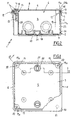
- the junction box 1 comprises a box body 2 destined to be applied to walls, infrastructures, or other supports.
- the box body 2 comprises a bottom wall 3 wherefrom extend peripherally and perpendicularly lateral walls 4 which define, with the bottom wall 3, a housing compartment 5 able to receive terminations of electrical conductors and/or other electrical elements.
- the box body 2 further presents an access opening 6 defined along the terminal edges 7 of the lateral walls 4. Through the access opening 6 it is possible to operate inside the box body 2, to arrange and install the electrical conductors and/or other components.
- the box 1 further comprises a cover 8 removably engageable to the box body 2 in correspondence with the access opening 6 to close the housing compartment 5.
- the cover 8 presents a cap 9 wherefrom a peripheral border 10 extends perpendicularly, which border 10, when the cover 8 closes the housing compartment 5, engages the terminal edges 7 of the lateral walls 4.
- the box 1 comprises closure means 11 operating between the box body 2 and the cover 8 to fasten them with respect to one other.
- closure means 11 comprise pressure fastening means 12 and screw-on fastening means 13 to maintain the cover 8 engaged to the box body 2.
- the pressure fastening means 12 provide for the presence of one or more projections 14 that protrude externally from the lateral walls 4 of the box body 2 and extend parallel to the terminal edges 7 of the lateral walls themselves.
- Each projection 14 is able to interact by mechanical interference with an overhang 15 protruding internally from the peripheral border 10 of the cover 8, to determine the snap-on closure of the cover 8 on the box body 2.
- the overhang 15 is parallel to the peripheral border 10 and can for instance develop along the entire inner surface of the lateral border itself or it can be realised in various segments situated on the same plane.
- the screw-on fastening means 13 provide for one or more cylindrical projections 16 to project from a lower surface of the cap 9, oriented internally to the compartment 5, terminally to said projections 16 being defined striking surfaces 17 oriented opposite to the cap itself.
- Each of the cylindrical projections 16, situated in correspondence with the four angles defined by the lateral walls 4, is axially traversed by an engagement hole 18 destined to receive a respective threaded element, shown in dashed lines in Figure 2.
- each of the cylindrical projections 16 is combined at least an attachment block 19 positioned in the housing compartment 5 and presenting at least a bearing surface 19a in correspondence whereto is obtained at least a screw hole 20.
- each engagement hole 18 is aligned with the screw hole 20 of the respective attachment block 19 present in the housing compartment 5, and each striking surface 17 is positioned against the respective bearing surface 19a.
- the engagement holes 18 can be obtained directly on the lower surface of the cap 9 of the cover 8 if the latter has sufficient thickness.
- each engagement hole 18 the cover 8 presents at least a frangible portion 21, extending in a relationship of superficial continuity with the cap 9.
- Each frangible portion 21 occludes the respective engagement hole 18 to assure a continuous external surface of the cover, when the screw-on fastening means are not used.
- frangible portions 21 are suitable to be penetrated by the respective threaded elements when the latter are inserted through the engagement holes 18 to be screwed into the screw holes 20.
- hermetic sealing means 22 to prevent fluid infiltrations into the housing compartment 5.
- sealing means 22 comprise one or more gaskets 23 which are interposed and compressed each between the respective striking surface 17 and bearing surface 19a, when the cover 8 and the box body 2 are mutually fastened by means of the threaded elements.
- the sealing means 22 further comprise at least a protective sheath 24 developing inside the box body 2 according to the entire superficial development of the housing compartment 5.
- Such protective sheath 24 projects from the housing compartment 5 along the entire peripheral development of the access opening 6 to form a lip-shaped sealing portion 24a.
- fairlead elements 25 suitable to occlude respective through holes 26 obtained through the lateral walls 4 and/or the bottom wall 3 of the box body 2.
- Each fairlead element 25 presents a series of concentric pre-breaking notches 25a whose purpose is to facilitate the penetration of the fairlead element itself according to a diameter suitable to obtain a sealing action on a cable or on a tube inserted through the fairlead element.
- breakable attachment seats 27 on the bottom wall 3 of the box body 2 are obtained one or more breakable attachment seats 27, by means of which the box body 2 can be fastened to a supporting wall, with the aid of additional threaded elements.
- a protective projection 28 develops, whereon is removably engageable a protective plug 29 suitable to cover the attachment seat 27 to prevent any fluids from infiltrating into the box body through the attachment seat itself.
- the various components destined to provide the hermetic seal such as the gaskets 23, the protective sheath 24 defining the lip 24a and the fairlead elements 25 that maintain perfectly closed the respective through openings 26, are realised in the same elastomeric material, obtained from a single piece by means of a co-moulding process with the plastic material whereof the box body 2 is made.
- the aforementioned components destined to provide the hermetic seal are joined to form a single sealing body, incorporating the gaskets 23 integral with the respective bearing surfaces 19a of the blocks 19, the protective sheath 24 as well as the closure elements 25 integral with the box body 2.
- junction box 1 is further provided with sealing means 30 operating between the cover and the box body to indicate any tampering with the components housed in the box 1 or otherwise the unauthorised removal of the cover 8.
- sealing means essentially comprise holed flap elements 30a, 30b respectively associated to the box body 2 and to the cover 8 and able to the traversed by a wire sealed with lead or other type of seal suitable for being necessarily broken upon opening the cover itself.
- the present invention attains its proposed aims.
- the subject junction box presents an improved versatility of use, thanks to the presence both of the snap-on closure means, and of the screw-on closure means.
- the screw-on fastening means 13 When, to assure a greater engagement reliability of the cover 8, the screw-on fastening means 13 are employed, fastening the threaded elements determines the compression of the gaskets 23 between the respective striking surfaces 17 and bearing surfaces 19a, hampering any infiltrations in correspondence with the surfaces themselves.
- the obtainment of the gaskets 23 in a single piece with the box 1 and with all other components (protective sheath 24, sealing lip 24a, fairlead elements 25) destined to guarantee the hermetic seal also represents an advantageous aspect for purposes of the hermetic seal, and considerably simplifies the process whereby the box is manufactured.
Landscapes
- Engineering & Computer Science (AREA)
- Architecture (AREA)
- Civil Engineering (AREA)
- Structural Engineering (AREA)
- Casings For Electric Apparatus (AREA)
- Connection Or Junction Boxes (AREA)
- Connector Housings Or Holding Contact Members (AREA)
- Cable Accessories (AREA)
Priority Applications (3)
| Application Number | Priority Date | Filing Date | Title |
|---|---|---|---|
| AT99830377T ATE477608T1 (de) | 1999-06-17 | 1999-06-17 | Elektrisches verbindungsgehäuse |
| EP99830377A EP1061624B1 (fr) | 1999-06-17 | 1999-06-17 | Boîtier électrique de jonction |
| DE69942665T DE69942665D1 (de) | 1999-06-17 | 1999-06-17 | Elektrisches Verbindungsgehäuse |
Applications Claiming Priority (1)
| Application Number | Priority Date | Filing Date | Title |
|---|---|---|---|
| EP99830377A EP1061624B1 (fr) | 1999-06-17 | 1999-06-17 | Boîtier électrique de jonction |
Publications (2)
| Publication Number | Publication Date |
|---|---|
| EP1061624A1 true EP1061624A1 (fr) | 2000-12-20 |
| EP1061624B1 EP1061624B1 (fr) | 2010-08-11 |
Family
ID=8243456
Family Applications (1)
| Application Number | Title | Priority Date | Filing Date |
|---|---|---|---|
| EP99830377A Expired - Lifetime EP1061624B1 (fr) | 1999-06-17 | 1999-06-17 | Boîtier électrique de jonction |
Country Status (3)
| Country | Link |
|---|---|
| EP (1) | EP1061624B1 (fr) |
| AT (1) | ATE477608T1 (fr) |
| DE (1) | DE69942665D1 (fr) |
Cited By (6)
| Publication number | Priority date | Publication date | Assignee | Title |
|---|---|---|---|---|
| ES2198214A1 (es) * | 2002-07-01 | 2004-01-16 | Hispano Mecano Electrica Sa | Perfeccionamientos en las cajas de conexiones electricas de fachada. |
| AU2004202049B2 (en) * | 2003-05-13 | 2005-03-17 | Rteck Pacific Limited | Junction box |
| EP2404644A1 (fr) * | 2010-07-07 | 2012-01-11 | Uponor Innovation AB | Boîtier de tête d'arroseur |
| GB2552394A (en) * | 2016-11-17 | 2018-01-24 | Gch Prec Engineering Ltd | Pressurised junction box manifild |
| CN108336702A (zh) * | 2018-03-05 | 2018-07-27 | 国网甘肃省电力公司经济技术研究院 | 一种电气接线盒 |
| CN111497767A (zh) * | 2020-04-23 | 2020-08-07 | 上海沪工汽车电器有限公司 | 一种车用中央电气接线盒下盖防护盖结构 |
Citations (3)
| Publication number | Priority date | Publication date | Assignee | Title |
|---|---|---|---|---|
| DE7833886U1 (de) | 1978-11-15 | 1979-02-22 | Buendoplast Gmbh & Co Kg, 4980 Buende | Einbaugehäuse aus Kunststoff |
| FR2689331A1 (fr) * | 1992-03-27 | 1993-10-01 | Legrand Sa | Embout à rapporter sur une paroi pour y constituer une sortie de câble. |
| EP0899843A2 (fr) | 1997-08-26 | 1999-03-03 | GE power Controls Belgium N.V. | Cache avec au moins une entrée, et une boíte de jonction avec un tel cache |
-
1999
- 1999-06-17 EP EP99830377A patent/EP1061624B1/fr not_active Expired - Lifetime
- 1999-06-17 DE DE69942665T patent/DE69942665D1/de not_active Expired - Lifetime
- 1999-06-17 AT AT99830377T patent/ATE477608T1/de active
Patent Citations (3)
| Publication number | Priority date | Publication date | Assignee | Title |
|---|---|---|---|---|
| DE7833886U1 (de) | 1978-11-15 | 1979-02-22 | Buendoplast Gmbh & Co Kg, 4980 Buende | Einbaugehäuse aus Kunststoff |
| FR2689331A1 (fr) * | 1992-03-27 | 1993-10-01 | Legrand Sa | Embout à rapporter sur une paroi pour y constituer une sortie de câble. |
| EP0899843A2 (fr) | 1997-08-26 | 1999-03-03 | GE power Controls Belgium N.V. | Cache avec au moins une entrée, et une boíte de jonction avec un tel cache |
Cited By (8)
| Publication number | Priority date | Publication date | Assignee | Title |
|---|---|---|---|---|
| ES2198214A1 (es) * | 2002-07-01 | 2004-01-16 | Hispano Mecano Electrica Sa | Perfeccionamientos en las cajas de conexiones electricas de fachada. |
| AU2004202049B2 (en) * | 2003-05-13 | 2005-03-17 | Rteck Pacific Limited | Junction box |
| EP2404644A1 (fr) * | 2010-07-07 | 2012-01-11 | Uponor Innovation AB | Boîtier de tête d'arroseur |
| GB2552394A (en) * | 2016-11-17 | 2018-01-24 | Gch Prec Engineering Ltd | Pressurised junction box manifild |
| GB2552394B (en) * | 2016-11-17 | 2019-06-05 | Gch Prec Engineering Ltd | Pressurised junction box manifold |
| CN108336702A (zh) * | 2018-03-05 | 2018-07-27 | 国网甘肃省电力公司经济技术研究院 | 一种电气接线盒 |
| CN108336702B (zh) * | 2018-03-05 | 2024-05-28 | 国网甘肃省电力公司经济技术研究院 | 一种电气接线盒 |
| CN111497767A (zh) * | 2020-04-23 | 2020-08-07 | 上海沪工汽车电器有限公司 | 一种车用中央电气接线盒下盖防护盖结构 |
Also Published As
| Publication number | Publication date |
|---|---|
| ATE477608T1 (de) | 2010-08-15 |
| EP1061624B1 (fr) | 2010-08-11 |
| DE69942665D1 (de) | 2010-09-23 |
Similar Documents
| Publication | Publication Date | Title |
|---|---|---|
| US6768054B2 (en) | Waterproof structure of electronic parts-containing box | |
| CA2658269C (fr) | Ensemble de couvercle de soulevement et de joint d'etancheite | |
| EP0677214B1 (fr) | Ensemble de base de derivation pour canalisation electrique prefabriquee | |
| EP2486635B1 (fr) | Joint pour câbles électriques | |
| US20130221813A1 (en) | Frame for cabinet, in particular for a switchgear cabinet | |
| EP3584121B1 (fr) | Boîtier, boîte de connexion électrique et faisceau de câbles | |
| EP1061624B1 (fr) | Boîtier électrique de jonction | |
| US4266683A (en) | Outdoor junction box | |
| EP0683544A2 (fr) | Système de mise à la terre | |
| CA2743286A1 (fr) | Dispositif d'entree de cable pour boites de connexion | |
| CN210986736U (zh) | 电气密封箱 | |
| EP1154392B1 (fr) | Sceaux de sécurité | |
| JP2004242434A (ja) | 電気接続箱の防水構造 | |
| JP6119506B2 (ja) | ドア用グロメット及びグロメット付ワイヤーハーネス | |
| JP4310764B2 (ja) | マンホール蓋の固定装置における水漏れ防止装置 | |
| CN221552266U (zh) | 连接器密封结构及线缆 | |
| GB2432979A (en) | Electrical connection unit with sealed housing inside lid | |
| KR200219109Y1 (ko) | 맨홀의 뚜껑장치 | |
| JP3681767B2 (ja) | 電子機器収納用筐体 | |
| AU5260799A (en) | Enclosure, in particular cabinet, having a back incorporating at least one hole blocked by a plug, in particular for electrical equipment | |
| KR200247046Y1 (ko) | 맨홀내부의 방수장치 | |
| KR200400837Y1 (ko) | 원터치 와이어방식 봉인장치 | |
| JPH07205657A (ja) | 自動車ドアのシール体 | |
| JPH10108412A (ja) | 電装部品の保護装置 | |
| MXPA94006564A (en) | Connector guide point base set to prevent dust and liquid entry |
Legal Events
| Date | Code | Title | Description |
|---|---|---|---|
| PUAI | Public reference made under article 153(3) epc to a published international application that has entered the european phase |
Free format text: ORIGINAL CODE: 0009012 |
|
| AK | Designated contracting states |
Kind code of ref document: A1 Designated state(s): AT BE DE ES FR GB IT NL PT SE |
|
| AX | Request for extension of the european patent |
Free format text: AL;LT;LV;MK;RO;SI |
|
| 17P | Request for examination filed |
Effective date: 20010618 |
|
| AKX | Designation fees paid |
Free format text: AT BE DE ES FR GB IT NL PT SE |
|
| 17Q | First examination report despatched |
Effective date: 20071213 |
|
| GRAP | Despatch of communication of intention to grant a patent |
Free format text: ORIGINAL CODE: EPIDOSNIGR1 |
|
| GRAS | Grant fee paid |
Free format text: ORIGINAL CODE: EPIDOSNIGR3 |
|
| GRAA | (expected) grant |
Free format text: ORIGINAL CODE: 0009210 |
|
| AK | Designated contracting states |
Kind code of ref document: B1 Designated state(s): AT BE DE ES FR GB IT NL PT SE |
|
| REG | Reference to a national code |
Ref country code: GB Ref legal event code: FG4D |
|
| REF | Corresponds to: |
Ref document number: 69942665 Country of ref document: DE Date of ref document: 20100923 Kind code of ref document: P |
|
| REG | Reference to a national code |
Ref country code: NL Ref legal event code: VDEP Effective date: 20100811 |
|
| PG25 | Lapsed in a contracting state [announced via postgrant information from national office to epo] |
Ref country code: NL Free format text: LAPSE BECAUSE OF FAILURE TO SUBMIT A TRANSLATION OF THE DESCRIPTION OR TO PAY THE FEE WITHIN THE PRESCRIBED TIME-LIMIT Effective date: 20100811 |
|
| PG25 | Lapsed in a contracting state [announced via postgrant information from national office to epo] |
Ref country code: PT Free format text: LAPSE BECAUSE OF FAILURE TO SUBMIT A TRANSLATION OF THE DESCRIPTION OR TO PAY THE FEE WITHIN THE PRESCRIBED TIME-LIMIT Effective date: 20101213 |
|
| PG25 | Lapsed in a contracting state [announced via postgrant information from national office to epo] |
Ref country code: BE Free format text: LAPSE BECAUSE OF FAILURE TO SUBMIT A TRANSLATION OF THE DESCRIPTION OR TO PAY THE FEE WITHIN THE PRESCRIBED TIME-LIMIT Effective date: 20100811 Ref country code: SE Free format text: LAPSE BECAUSE OF FAILURE TO SUBMIT A TRANSLATION OF THE DESCRIPTION OR TO PAY THE FEE WITHIN THE PRESCRIBED TIME-LIMIT Effective date: 20100811 |
|
| PLBE | No opposition filed within time limit |
Free format text: ORIGINAL CODE: 0009261 |
|
| STAA | Information on the status of an ep patent application or granted ep patent |
Free format text: STATUS: NO OPPOSITION FILED WITHIN TIME LIMIT |
|
| PG25 | Lapsed in a contracting state [announced via postgrant information from national office to epo] |
Ref country code: ES Free format text: LAPSE BECAUSE OF FAILURE TO SUBMIT A TRANSLATION OF THE DESCRIPTION OR TO PAY THE FEE WITHIN THE PRESCRIBED TIME-LIMIT Effective date: 20101122 |
|
| 26N | No opposition filed |
Effective date: 20110512 |
|
| PGFP | Annual fee paid to national office [announced via postgrant information from national office to epo] |
Ref country code: AT Payment date: 20110624 Year of fee payment: 13 |
|
| REG | Reference to a national code |
Ref country code: DE Ref legal event code: R097 Ref document number: 69942665 Country of ref document: DE Effective date: 20110512 |
|
| PGFP | Annual fee paid to national office [announced via postgrant information from national office to epo] |
Ref country code: FR Payment date: 20110722 Year of fee payment: 13 |
|
| PGFP | Annual fee paid to national office [announced via postgrant information from national office to epo] |
Ref country code: DE Payment date: 20110830 Year of fee payment: 13 |
|
| PGFP | Annual fee paid to national office [announced via postgrant information from national office to epo] |
Ref country code: IT Payment date: 20110628 Year of fee payment: 13 |
|
| GBPC | Gb: european patent ceased through non-payment of renewal fee |
Effective date: 20110617 |
|
| PG25 | Lapsed in a contracting state [announced via postgrant information from national office to epo] |
Ref country code: GB Free format text: LAPSE BECAUSE OF NON-PAYMENT OF DUE FEES Effective date: 20110617 |
|
| REG | Reference to a national code |
Ref country code: AT Ref legal event code: MM01 Ref document number: 477608 Country of ref document: AT Kind code of ref document: T Effective date: 20120617 |
|
| PG25 | Lapsed in a contracting state [announced via postgrant information from national office to epo] |
Ref country code: IT Free format text: LAPSE BECAUSE OF NON-PAYMENT OF DUE FEES Effective date: 20120617 |
|
| REG | Reference to a national code |
Ref country code: FR Ref legal event code: ST Effective date: 20130228 |
|
| PG25 | Lapsed in a contracting state [announced via postgrant information from national office to epo] |
Ref country code: FR Free format text: LAPSE BECAUSE OF NON-PAYMENT OF DUE FEES Effective date: 20120702 Ref country code: DE Free format text: LAPSE BECAUSE OF NON-PAYMENT OF DUE FEES Effective date: 20130101 |
|
| REG | Reference to a national code |
Ref country code: DE Ref legal event code: R119 Ref document number: 69942665 Country of ref document: DE Effective date: 20130101 |
|
| PG25 | Lapsed in a contracting state [announced via postgrant information from national office to epo] |
Ref country code: AT Free format text: LAPSE BECAUSE OF NON-PAYMENT OF DUE FEES Effective date: 20120617 |