EP1061657A2 - Audiogerät und Verfahren zur Steuerung eines Audiosystems - Google Patents
Audiogerät und Verfahren zur Steuerung eines Audiosystems Download PDFInfo
- Publication number
- EP1061657A2 EP1061657A2 EP00111952A EP00111952A EP1061657A2 EP 1061657 A2 EP1061657 A2 EP 1061657A2 EP 00111952 A EP00111952 A EP 00111952A EP 00111952 A EP00111952 A EP 00111952A EP 1061657 A2 EP1061657 A2 EP 1061657A2
- Authority
- EP
- European Patent Office
- Prior art keywords
- section
- command
- control
- audio apparatus
- control target
- Prior art date
- Legal status (The legal status is an assumption and is not a legal conclusion. Google has not performed a legal analysis and makes no representation as to the accuracy of the status listed.)
- Withdrawn
Links
Images



Classifications
-
- H—ELECTRICITY
- H04—ELECTRIC COMMUNICATION TECHNIQUE
- H04L—TRANSMISSION OF DIGITAL INFORMATION, e.g. TELEGRAPHIC COMMUNICATION
- H04L49/00—Packet switching elements
- H04L49/90—Buffering arrangements
Definitions
- the present invention relates to an audio apparatus, a controller, an audio system, and a method of controlling an audio apparatus, and in particular, to a technique to establish, when a computer is connected to an audio apparatus, synchronization between the computer and the audio apparatus.
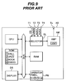
- Fig. 9 shows a block diagram of an outline of an amplifier system as an example of a stand-alone audio system of the prior art.
- An external compact disk (CD) player supplies a digital audio signal or an analog audio signal to a CD player terminal T1.
- An external tuner inputs an analog audio signal to a tuner terminal T2.
- Other audio signals are fed to a first auxiliary terminal T3 and a second auxiliary terminal T4.
- An input selector SL is connected to the terminals T1 to T4.
- the selector SL includes a digital-to-analog (D/A) converter and an analog-to-digital (A/D) converter, which are not shown.
- An analog audio signal is delivered via the selector SL to an audio amplifier section AM.
- the amplifier section AM includes a digital signal processor (DSWP) and amplifies the audio signal, and then outputs the amplified signal to a speaker terminal Ts.
- DSP digital signal processor
- the terminal Ts is connected to a loudspeaker, not shown.
- a central processing unit (CPU) 150 controls the overall operation of the amplifier system AS.
- a read-only memory (ROM) 151 stores various programs for DSP, data for DSP, various control programs, and control data.
- a random access memory (RAM) 152 serves as a work area to temporarily store various data items.
- a display section 153 displays various information items such as a sound source being selected and a DSP mode.
- An operator panel 154 includes various types of operation keys.
- a bus 155 connects the input selector SL, the CPU 150, the ROM 151, the RAM 152, the display 153, and the operator panel 154 to each other.
- An external equipment inputs an analog audio signal via the selector SL to the amplifier section AM.
- the amplifier section AM amplifies the input signal and then outputs the amplified signal to the speaker terminal Ts.
- the speaker connected to the terminal Ts sounds.
- the display section 153 displays information of the selected sound source (e.g., a CD player) or the like.
- the DSP in the amplifier section AM reads from the ROM 151 a program corresponding to the selected DSP mode ("HALL”, “JAZZ”, “ROCK”, or “DISCO” mode) and conducts DSP for the digital audio signal stored in the DSP RAM.
- the amplifier section AM amplifies the analog audio signal resultant from the DSP and then outputs the amplified signal to the speaker terminal Ts.
- the speaker connected to the terminal Ts produces sound.
- the display section 153 displays information of the selected sound source (e.g., a CD player), the selected DSP mode (e.g., "JAZZ”), and the like.
- the selected sound source e.g., a CD player
- the selected DSP mode e.g., "JAZZ”
- the computer and the audio apparatus are in operation independent to each other. Consequently, for example, when transmission error of control data sent from the computer to the audio apparatus occurs, a state of operation of the audio apparatus in the computer may possibly differ from the actual state of operation of the audio apparatus.
- control operation can differ from what the user desires.
- the state of operation of the audio apparatus displayed on the display screen matches the actual state of operation thereof in any situation. Consequently, the user can make the audio apparatus conduct operation as desired by the user.
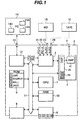
- Fig. 1 shows a general block diagram of an embodiment of an audio system according to the present invention.
- the audio system 1 includes a receiver 2 and a personal computer 14.
- the receiver 2 includes a tuner section, not shown.
- the personal computer 14 is connected via a USB interface 12 to the receiver 2 to control the receiver 2. If desired, the user can expand the audio system 1 by connecting a mini-disk (MD) player 15 to a first auxiliary terminal 23, which will be described later, and/or a tape deck 16 to a second auxiliary terminal 24, which will be described later.
- MD mini-disk
- a digital audio signal from a sound card of the personal computer 14 is inputted to a digital audio signal terminal 21.
- An analog audio signal from a sound card of the computer 14 is fed to an analog audio signal terminal 22.
- a digital or analog audio signal from an external digital audio (recording) reproducing device such as an MD player is delivered to the first auxiliary terminal 23.
- An analog audio signal from an external digital audio (recording) reproducing device such as the tape deck 16 is delivered to the second auxiliary terminal 24.
- the signal connecting terminals 21 to 24 are connected to an input selector 3.
- An audio signal via USB, i.e., PC-U is inputted via a USB interface 12, which will be described later, to the selector 3.
- the selector 3 includes an A/D converter.
- An audio amplifier 4 conducts digital signal processing for the analog audio signal received via the selector 3, amplifies the audio signal, and outputs the amplified signal to a speaker terminal 5.
- the terminal 5 is connected to a speaker.
- the receiver 2 also includes an operator panel 6 including various operation keys.
- a CPU 7 supervises the overall operation of the receiver 2.
- a display 8 displays various information items such as a sound source being selected and a DSP mode.
- An ROM 9 stores various programs for DSP, data for DSP, various control programs, and control data.
- An RAM 10 serves as a work area to temporarily store various data.
- the USB interface 12 communicates signals via a USB terminal 13 with the personal computer 14. Specifically, the USB interface 12 transfers a control signal received from the computer 14 to a bus 11 and a control signal received from the bus 11 to the computer 14. On receiving an audio signal (PC-U) from the computer 14, the USB interface 12 sends the signal to the input selector 3.
- PC-U an audio signal
- the audio amplifier 4 includes an amplifier 41 to amplify an audio signal, an RAM 49 to serve also as a work area, and a sound field processor 18 to conduct sound field processing through digital signal processing.
- the bus 11 connects the input selector 3, the audio amplifier 4, the operator panel 6, the CPU 7, the display 8, the ROM 9, the RAM 10, and the USB interface 12 to each other.
- the RAMs 10 and 49 are connected to a backup power source, not shown. Even if the system is not powered, data can be kept retained therein, for example, about one week.
- Fig. 2 shows a front view of a front panel of the receiver 2.
- the front panel of the receiver 2 includes a plurality of switches partly constituting the operation panel 6.
- Selector switches 6a1 to 6a4 select a sound source.
- a DSP switch 6b indicates whether or not the DSP is operated.
- a preset switch 6c which can be set to on exclusively with respect to the DSP switch 6b, indicates whether or not preset station selection is desired to function when the tuner section is in use.
- a pair of up/down switches 6d and 6e function as a DSP mode selection switch.
- the preset switch 6c When the preset switch 6c is on, the switches 6d and 6e function as a station selection switch.
- a volume control 6f adjusts magnitude of sound volume.
- a power switch 6g turns power on/off.
- the front panel of the receiver 2 includes a headphone jack 5p to connect a headphone.
- the front panel of receiver 2 further includes display sections each constituting a part oh the display 8.
- a multifunctional display section 8d which includes a dot-matrix transmission liquid crystal display (LCD) with a backlight or a fluorescent luminescence (FL) display element, displays various information.
- a first indicator 8i1 turns on.
- a second indicator 8i2 turns on.
- a third indicator 8i3 turns on.
- a fourth indicator 8i4 turns on.
- a power indicator 8p turns on.
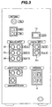
- Fig. 3 shows a front view of a rear panel of the receiver 2.
- the first auxiliary terminal 23 includes a digital audio auxiliary terminal 23 1 to receive a digital audio signal from an external digital (recording) reproducing device and an analog audio auxiliary terminal 23 2 to receive an analog audio signal from an external digital (recording) reproducing device.
- the rear panel further includes a USB terminal 13, antenna terminals (an FM antenna terminal, an AM antenna terminal, and a ground terminal), an analog audio output terminal, and a subwoofer output terminal.
- the USB interface standard stipulates a control command including a set request command and a get request command.
- the set request command is provided for the personal computer 14 to set values to various parameters of the receiver 2.
- the get request command is used by the computer 14 to read the values of parameters from the receiver 2.
- the control command also includes an audio class control command to handle audio signals.
- Fig. 4 shows a format of an audio class control command 20.
- the command 20 includes an 8-byte audio class header 20A to indicate that this command is an audio class control command and an x-byte data field 20B (x varies depending on the control command).
- This embodiment uses, in place of an audio class control command, an HID class control command in which control operation thereof can be freely defined.
- Fig. 5 shows a data format of an HID class control command 30 to handle audio signals.
- the command 30 includes an 8-byte HID class header 30A and a data field 30B.
- the data field 30B includes an 8-byte header 30C and an 8-byte data field 30D (respectively indicated as @PET Header and @PET Data in Fig. 5).
- the header 30C indicates that this command is a control command equivalent to an audio class control command.
- the receiver 2 When a state of the receiver 2 changes, the receiver 2 issues a control command.
- a control command an audio class control command is used with specifications of, e.g., control of sound volume.
- the receiver 2 sends an HID class control command in place of an audio class control command to the computer 14.
- the header 30C of the HID class control command is set to a value of the header for the get request command of the audio class control command and the data field 30D is set to data of the audio class control command.
- the computer 14 includes a display with operator panel (display) 14A, a central processing unit 14B, and a read unit 14C.
- the user To operate the receiver 2 via the computer 14, the user conducts operation in a GUI screen displayed on the display 14A.
- Fig. 6 shows an example of the GUI screen.
- the display 14A of the computer 14 displays a GUI screen 2G graphically similar to a front panel of the receiver 2.
- the screen 2G includes selector switch items 6a1 to 6a4 respectively corresponding to selector switches 6a1 to 6a4 for sound source selection, a DSP switch item G6b corresponding to the DSP switch to indicate whether or not the DSP is to be operated, a preset switch item G6c associated with the preset switch 6c to indicate whether or not preset selection is required when the tuner section is in use, up and down switch items G6d and G6e correspond to the up and down switches 6d and 6e, a sound volume adjuster item G6f corresponds to the sound volume adjuster 6f, and a power switch item G6g associated with a power switch 6g to turn power on or off.
- These switch items G6a to G6g are arranged in almost the same way as for the associated switches on the front panel of the receiver 2.
- the screen 2G further includes a headphone jack item G5p, which turns on when a headphone is connected to the headphone jack 5p.
- the screen 2G also includes a multifunctional display window item G8d corresponding to the multifunctional display section 8d to display various information, first to fourth indicator items G8i1 to G8i4 respectively corresponding the indicators 8i1 to 8i4, and a power indicator item G8p corresponding to the power indicator 8p which turns on when the system is powered.
- the user moves the cursor CUR to a position over a target item by a pointing device such as a mouse.
- a pointing device such as a mouse.
- the volume control 6f When the user moves the cursor CUR to a position over the volume control item G6f and holds the left button (to keep the left button in a depressed state), it is recognized that the volume control 6f is turned to increase magnitude of sound volume for a period of time in which the item G6f is kept held. If the user hods the right button, the system interprets that the volume control 6f is rotate to decrease magnitude of sound volume for a period of time in which the item G6f is kept held.
- the multifunctional display window item G8d displays various information in response to operation conducted almost in the same way as for the multifunctional display section 8d of the receiver 2.
- the first to fourth indicator items G8i1 to G8i4 and the power indicator item G8p respectively reflect the on or off states of the indicators, respectively corresponding to these indicator items, on the front panel of the receiver 2.
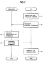
- Fig. 7 is a sequence flowchart for the GUI screen operation. In this description of specific operation, a sound source is selected by a 2-button mouse.
- the user clicks the left button of the mouse (step S1).
- the CPU (microprocessor) 14B of the computer 14 determines the item indicated by the cursor CUR.
- the microprocessor 14B generates a control command (set request command) notifying the activation of the selector switch item G6ax and transmits the command via the USB terminal 13 to the receiver 2 (step 2).
- step S3 when the CPU 7 of the receiver 2 receives the control command (set request command) via the USB terminal 13 and the USB interface 12, the CPU 7 executes processing associated with the set request command (step S3).
- the processing is almost the same as that achieved when the selector switch 6ax is depressed.
- the CPU 7 controls the input selector 3 to connect the terminal corresponding to the selector switch 6ax to the audio amplifier 4. If the DSP switch 6b is kept depressed, the CPU 7 connects the pertinent terminal via an A/D converter, not shown, to the RAM 49 in the sound field processor (DSP) 18. Thereafter, the indicator 8ix is set to on.
- the CPU 7 generates a response command (set request command) including a result of the command processing and sends the command via the bus 11, the USB interface 12, and the SB terminal 13 to the computer 14 (step S4).
- the CPU 7 receives a response command (set request command) from the microprocessor 14B of the computer 14. Having received the set request command, the receiver 2 confirms execution of processing which is almost the same as the processing for depression of the selector switch 6ax and then turns the indicator display item G8ix corresponding to the selector switch G6ax on.
- the computer 14 When a predetermined time lapses before a response command is received from the receiver 2, the computer 14 assumes that the control command sent from the computer 14 is not appropriately accepted. The computer 14 therefore keeps the GUI screen 2G (such as the on or off state of the pertinent indicator item) unchanged.
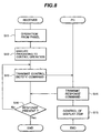
- Fig. 8 is a flowchart of a sequence of operation on the panel of the receiver 2. Also in this case, the operation is conducted to select a sound source.
- the CPU 7 determines the depressed selector switch and executes processing to control operation corresponding to the selector switch (step S12).
- the CPU 7 generates a control command (set request command) indicating that the selector switch has been depressed and sends the command via the bus 11, the USB interface 12, and the USB terminal 13 to the computer 14 (step S13).
- the computer 14 Having received the set request command indicating depression of one of the selector switches 6ax, the computer 14 generates a response command (set request command) notifying reception of the set request command and sends the command to the receiver 2 (step S14). The computer 14 then turns the indicator item G8ix corresponding to the selector switch G6ax on (step S15).
- step S12 it is impossible for the receiver 2 to determine whether or not the set request command of step S12 has been completely sent to the computer 14. Therefore, if a predetermined time lapses before a response command is received, the CPU 7 assumes that the control command transmitted in step 13 has not been transmitted (no in step S16) and hence returns to step S13 to transmit again the control command. The CPU 7 repeatedly executes this processing until a response command is received from the computer 14.
- the receiver 2 controls operation according to a state of the panel operated by the user. This minimizes the response time of operation of the receiver 2 and increases usability thereof for the user.
- the state of operation of the receiver 2 completely reflects on the GUI screen 2G of the display 14A. Therefore, the state of operation displayed on the GUI screen 2G matches the actual state of operation of the receiver 2 in any cases.
- the state of operation displayed on the GUI screen always matches the actual state of operation in the receiver 2. Therefore, the operation can be controlled as the user desires.
- the GUI screen is similar to the panel of the receiver or the GUI includes items arranged in almost the same way as for the associated indicators on the panel. Consequently, even if the user rarely operates the receiver 2 in usual situations, it is possible for the user to learn actual operation of the receiver 2 by operating the ordinary personal computer 14 to activate the receiver 2.
- USB interface is used between the personal computer and the receiver.
- the embodiment is applicable also to an apparatus employing an interface standard in which no response is returned to a control command.
- the embodiment is also applicable to other audio (visual) apparatuses such as an amplifier, a tuner, a CD player, a digital video disk (DVD) player, and a digital audio tape (DAT) player.
- audio visual
- an amplifier such as an amplifier, a tuner, a CD player, a digital video disk (DVD) player, and a digital audio tape (DAT) player.
- tuner such as an amplifier, a tuner, a CD player, a digital video disk (DVD) player, and a digital audio tape (DAT) player.
- DAT digital audio tape
Landscapes
- Engineering & Computer Science (AREA)
- Computer Networks & Wireless Communication (AREA)
- Signal Processing (AREA)
- Control Of Amplification And Gain Control (AREA)
- Selective Calling Equipment (AREA)
- User Interface Of Digital Computer (AREA)
Applications Claiming Priority (2)
| Application Number | Priority Date | Filing Date | Title |
|---|---|---|---|
| JP16902199 | 1999-06-15 | ||
| JP16902199A JP4421010B2 (ja) | 1999-06-15 | 1999-06-15 | オーディオシステム |
Publications (2)
| Publication Number | Publication Date |
|---|---|
| EP1061657A2 true EP1061657A2 (de) | 2000-12-20 |
| EP1061657A3 EP1061657A3 (de) | 2003-06-11 |
Family
ID=15878867
Family Applications (1)
| Application Number | Title | Priority Date | Filing Date |
|---|---|---|---|
| EP20000111952 Withdrawn EP1061657A3 (de) | 1999-06-15 | 2000-06-15 | Audiogerät und Verfahren zur Steuerung eines Audiosystems |
Country Status (2)
| Country | Link |
|---|---|
| EP (1) | EP1061657A3 (de) |
| JP (1) | JP4421010B2 (de) |
Cited By (2)
| Publication number | Priority date | Publication date | Assignee | Title |
|---|---|---|---|---|
| US8526637B2 (en) | 2009-12-11 | 2013-09-03 | Onkyo Corporation | Volume control apparatus and program of volume control apparatus |
| US8571236B2 (en) | 2010-02-26 | 2013-10-29 | Onkyo Corporation | Volume control system, controller, and amplifying apparatus |
Families Citing this family (3)
| Publication number | Priority date | Publication date | Assignee | Title |
|---|---|---|---|---|
| JP2008171496A (ja) * | 2007-01-11 | 2008-07-24 | Kenwood Corp | コンテンツ再生システム、ホスト側コンテンツ再生装置及び制御方法 |
| JP4908360B2 (ja) * | 2007-09-19 | 2012-04-04 | 株式会社東芝 | 携帯情報端末連係システムおよび連係処理プログラム並びに連係処理装置 |
| JP4998760B2 (ja) * | 2010-02-26 | 2012-08-15 | オンキヨー株式会社 | 音量調整システム |
Family Cites Families (3)
| Publication number | Priority date | Publication date | Assignee | Title |
|---|---|---|---|---|
| ES2130150T3 (es) * | 1991-03-22 | 1999-07-01 | D2B Systems Co Ltd | Sistema de bus de comunicacion local y aparatos para su uso en un sistema de este tipo. |
| US5565929A (en) * | 1992-10-13 | 1996-10-15 | Sony Corporation | Audio-visual control apparatus for determining a connection of appliances and controlling functions of appliances |
| JP3735942B2 (ja) * | 1996-06-04 | 2006-01-18 | ソニー株式会社 | 通信制御方法、通信システムおよびそれに用いる電子機器 |
-
1999
- 1999-06-15 JP JP16902199A patent/JP4421010B2/ja not_active Expired - Fee Related
-
2000
- 2000-06-15 EP EP20000111952 patent/EP1061657A3/de not_active Withdrawn
Cited By (2)
| Publication number | Priority date | Publication date | Assignee | Title |
|---|---|---|---|---|
| US8526637B2 (en) | 2009-12-11 | 2013-09-03 | Onkyo Corporation | Volume control apparatus and program of volume control apparatus |
| US8571236B2 (en) | 2010-02-26 | 2013-10-29 | Onkyo Corporation | Volume control system, controller, and amplifying apparatus |
Also Published As
| Publication number | Publication date |
|---|---|
| JP2000356991A (ja) | 2000-12-26 |
| EP1061657A3 (de) | 2003-06-11 |
| JP4421010B2 (ja) | 2010-02-24 |
Similar Documents
| Publication | Publication Date | Title |
|---|---|---|
| EP1061773B1 (de) | Audiosystem,Steuerungsverfahren und Speichermedium | |
| US10051228B2 (en) | Home theater system, audio/video playback device, audio output control device, and volume control method | |
| US7158842B2 (en) | Audio system and its contents reproduction method, audio apparatus for a vehicle and its contents reproduction method, computer program product and computer-readable storage medium | |
| JP2000083178A5 (ja) | 画像表示システム及びリモートコントロールシステム | |
| US7133730B1 (en) | Audio apparatus, controller, audio system, and method of controlling audio apparatus | |
| US20110211712A1 (en) | Volume control system, controller, and amplifying apparatus | |
| US7969279B2 (en) | Remote control system and presetting method for remote commander | |
| EP1061655B1 (de) | Audiosystem mit digitaler Signalbehandlung , und Verfahren zur Steuerung des Systems | |
| US20050049006A1 (en) | Mobile terminal for displaying a variable auxiliary display area and method thereof | |
| JP4421010B2 (ja) | オーディオシステム | |
| JP2004282754A (ja) | 映像信号及び/または音声信号を記録/再生できるディスプレイ装置及びその運用方法 | |
| EP1061774B1 (de) | Audiosystem mit einem Schallfeldprozessor | |
| EP1061658B1 (de) | Audiosystem mit grafischen Benutzerschnittstelle | |
| JP2005197951A (ja) | 電子機器 | |
| JP4289120B2 (ja) | 遠隔制御装置 | |
| US20060235887A1 (en) | Terminal device, content deletion and transfer control system, and method for controlling content deletion | |
| JP4971005B2 (ja) | 電子機器に接続された外部機器の接続情報認識システム及びその認識方法 | |
| JPH11143634A (ja) | リモコン装置 | |
| KR960015179B1 (ko) | 터치패널식 리모콘의 기능입력장치와 그 방법 | |
| JP3432875B2 (ja) | 電源復旧時のシステム再設定方法 | |
| JPH04326900A (ja) | 車載用データ通信システム | |
| JP2000276833A (ja) | 表示変更可能なオーディオシステム | |
| JP2008271293A (ja) | 双方向リモコンシステム | |
| JPH0740758B2 (ja) | 音響装置 | |
| JP2002208265A (ja) | 記録再生装置、記録再生装置の制御方法、および、記録媒体 |
Legal Events
| Date | Code | Title | Description |
|---|---|---|---|
| PUAI | Public reference made under article 153(3) epc to a published international application that has entered the european phase |
Free format text: ORIGINAL CODE: 0009012 |
|
| AK | Designated contracting states |
Kind code of ref document: A2 Designated state(s): AT BE CH CY DE DK ES FI FR GB GR IE IT LI LU MC NL PT SE |
|
| AX | Request for extension of the european patent |
Free format text: AL;LT;LV;MK;RO;SI |
|
| PUAL | Search report despatched |
Free format text: ORIGINAL CODE: 0009013 |
|
| AK | Designated contracting states |
Designated state(s): AT BE CH CY DE DK ES FI FR GB GR IE IT LI LU MC NL PT SE |
|
| AX | Request for extension of the european patent |
Extension state: AL LT LV MK RO SI |
|
| 17P | Request for examination filed |
Effective date: 20030730 |
|
| 17Q | First examination report despatched |
Effective date: 20031028 |
|
| AKX | Designation fees paid |
Designated state(s): DE FR GB |
|
| RAP1 | Party data changed (applicant data changed or rights of an application transferred) |
Owner name: YAMAHA CORPORATION |
|
| STAA | Information on the status of an ep patent application or granted ep patent |
Free format text: STATUS: THE APPLICATION IS DEEMED TO BE WITHDRAWN |
|
| 18D | Application deemed to be withdrawn |
Effective date: 20090415 |