EP1061658A2 - Sysème audio avec interface graphique utilisateur - Google Patents
Sysème audio avec interface graphique utilisateur Download PDFInfo
- Publication number
- EP1061658A2 EP1061658A2 EP00111953A EP00111953A EP1061658A2 EP 1061658 A2 EP1061658 A2 EP 1061658A2 EP 00111953 A EP00111953 A EP 00111953A EP 00111953 A EP00111953 A EP 00111953A EP 1061658 A2 EP1061658 A2 EP 1061658A2
- Authority
- EP
- European Patent Office
- Prior art keywords
- parameters
- display
- audio
- group
- user
- Prior art date
- Legal status (The legal status is an assumption and is not a legal conclusion. Google has not performed a legal analysis and makes no representation as to the accuracy of the status listed.)
- Granted
Links
- 238000000034 method Methods 0.000 claims abstract description 21
- 230000008569 process Effects 0.000 claims abstract description 21
- 230000005236 sound signal Effects 0.000 claims abstract description 15
- 230000006870 function Effects 0.000 description 17
- 238000010586 diagram Methods 0.000 description 15
- 230000008859 change Effects 0.000 description 8
- 238000012986 modification Methods 0.000 description 2
- 230000004048 modification Effects 0.000 description 2
- 101150093547 AUX1 gene Proteins 0.000 description 1
- 101100125299 Agrobacterium rhizogenes aux2 gene Proteins 0.000 description 1
- 101100367246 Saccharomyces cerevisiae (strain ATCC 204508 / S288c) SWA2 gene Proteins 0.000 description 1
- 239000003086 colorant Substances 0.000 description 1
- 238000004891 communication Methods 0.000 description 1
- 239000004973 liquid crystal related substance Substances 0.000 description 1
- 238000004020 luminiscence type Methods 0.000 description 1
- 238000004519 manufacturing process Methods 0.000 description 1
- 238000007789 sealing Methods 0.000 description 1
Images




Classifications
-
- H—ELECTRICITY
- H04—ELECTRIC COMMUNICATION TECHNIQUE
- H04L—TRANSMISSION OF DIGITAL INFORMATION, e.g. TELEGRAPHIC COMMUNICATION
- H04L49/00—Packet switching elements
- H04L49/90—Buffering arrangements
Definitions
- This invention relates to an audio system that performs a sound process based on a user preference.
- an audio device e.g., an amplifier or the like
- various kinds of parameters such as sound-field controls in addition to basic parameters like volume controls.
- the amplifier having various parameters should have many control switches, each of which is corresponding to each function or parameter, on its front panel in order to allow a user to set those parameters.
- an audio system wherein an audio device and a personal computer (PC) are connected each other.
- a user can edit music and text stored in the audio system from the PC.
- input means such as a keyboard, a graphical user interface (GUI) or the likes of the PC to control the audio device, various parameters can be set without placing so many switches on the audio device.
- GUI graphical user interface
- an audio device that has a remote control unit with switches, which are not placed on a main body of the audio device, is developed. According to such an audio device, the number of the switches placed on the main body of the audio device can be reduced. Also in this kind of the audio device, functions that cannot be displayed on a display of the main body may be displayed on a liquid crystal display (LCD) of the remote control unit or a television set.
- LCD liquid crystal display
- a program for displaying a setup menu of various functions on a display device of a PC and controlling those functions are stored in a memory of an audio device, and it is very difficult to change a setup display on the PC and functions being displayed. Therefore, a user cannot customize the setup display according to a preference.
- function switches once function switches are placed on the main body, the same functions are not controllable and viewed from the PC so that a user should manipulate both the main body of the audio device and the PC. Also, to confirm the setup, the user should lookup both of them.
- the audio device that has a remote control unit with switches displays information according to picture signals transmitted from the main body, it is very difficult to change a setup display. Also, a low ability of LCD of a remote controller may worsen the operability because of bad visibility.
- an audio system comprising: an audio apparatus comprising a processor that performs a sound process to an audio signal based on one or some of a first group of parameters and a second group of parameters, a switch with which a user can set one or some of said first group of parameters, and a first interface to which an external device is connected; and a control apparatus comprising a second interface to which said audio apparatus is connected, a display device that displays said second group of parameters, a reading device that reads a program stored in a storage medium, a display controller that controls a display of said display device based on said program read by said reading device and a graphical user interface displayed on said display device for setting one or some of said second group of parameters cooperating with said display device, a transmitter that transmits setting of said second group of parameters made by said graphical user interface to said audio apparatus.
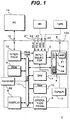
- FIG. 1 is a block diagram showing the structure of an audio system according to an embodiment of the invention.
- An audio system 1 has a receiver 2, a personal computer (PC) 14, a mini-disk (MD) player 15 and a cassette tape deck 16.
- PC personal computer
- MD mini-disk
- An audio device 100 has input lines 21 to 24 that are placed on a later-described rear panel of the device.
- the input lines 21 to 24 are connectors to which a digital or analog signal source, e.g., a personal computer (PC), a compact disc (CD) player, a mini disk player and a cassette tape deck, can be connected.
- the input line 21 is a connector for connecting a digital signal source from the PC.
- the input line 22 is a connector for connecting an analog signal source from the PC.
- the audio device 100 also has a tuner 17, an input selector 3 that selects an input from either one of the input lines 21 to 24 and has a built-in analog to digital (D/A) converter that converts analog signals input to the input selector 3 to digital signals, an audio amplifier 4 that performs various processes to an audio signal, and a speaker output 5 to which a loud speaker is connected.
- D/A analog to digital
- the audio amplifier 4 has a digital sound-field processor (DSP) unit 18 that performs a digital sound-field process and a three-dimensional (3D) sound-field process to a digital signal input from the input selector 3, an amplifier 41 that amplifies the digital signal processed in the DSP unit 18, and a random access memory (RAM) 49 that is used as a working area of the DSP unit 18 and temporally saving area of various data and parameters.
- DSP digital sound-field processor
- 3D three-dimensional
- the input selector 3 selects audio signals (source signals) from various audio sources. For example, the input selector 3 selects and outputs a signal form one of input lines 21 to 24, the tuner 17 and a later-described interface 12 connected to the PC 14.
- the output signal of the input selector 3 is processed in the DSP unit 18 in various ways (e.g., sound-field processing) and amplified in the amplifier 4.
- the processed signal is output from the speaker output 5 to be reproduced by a loudspeaker.
- the audio device 100 has a control panel 6, the central processing unit (CPU) 7, a display unit 8, a read only memory (ROM) 9 and a RAM 10, which are connected to each other through a bus 11.
- the control panel 6 allows a user to set various functions and parameters. In this specification, to set functions or parameters may also means to modify, to control or to select functions or parameters.
- the display unit 8 displays functions selected with the control panel 6 and the likes.
- the CPU 7 controls the audio system and performs various processes. For example, the CPU 7 controls the input selector 3 based on an outstanding status of the control panel 6 and on a later-described operational command transmitted from the PC 14.
- the ROM 9 stores various data and prescribed programs for controlling the audio system 1 consisted of the audio device 100 and the PC 14.
- the data stored in the ROM 9 includes, at least, data relating to set parameters, and the prescribed programs include, at least, a program for transmitting setting data from the control panel 6 or the PC 14 to the audio amplifier 4 and a program that allows a user to control the audio device 100 from the PC 14 when the PC 14 is connected to the audio device 100 through the interface 12.
- a user can set various parameters stored in the ROM 9 through the PC 14 or the control panel 6 in the audio device 100, and the audio amplifier 4 can process an audio signal input from the input selector 3.
- the various parameters stored in the ROM 9 can be divided into two groups.
- a first group (of parameters) includes parameters that can be set by manipulating the front panel 6, and a second group (of parameters) includes parameters that can be set only by manipulating the PC 14.
- the parameters of both groups are described later with examples.
- the RAM 10 and RAM 49 in the DSP unit are connected to backup power source. Therefore, they can hold their memory without main power of the audio device, for example, up to one week.
- the audio device 100 has the interface 12 and a PC connector 13.
- the interlace 12 is, for example, a universal serial bus (USB) interface or other type of interface that can input and output control signals to and from the bus 11 and output an audio signal (PC-U) to the input selector 3.
- the PC connector 13 is, for example, a USB connector or other type of connector to which the PC 14 is connected.
- the audio device 4 and the PC 14 are connected each other through the interface 12 and the PC connector 13 to make up the audio system 1.
- Fig. 2 is a diagram showing an example of a front panel of the audio device 100 of the embodiment.
- the control panel 6 is placed on the front panel of the audio device 1 and has key-switches, a dial or the likes far various settings, controls and modifications.
- key-switches a dial or the likes far various settings, controls and modifications.
- on the front panel are push-button-type input selection switches 6a1 to 6a4, a DSP switch 6b, a tuner setting switch 6c, DSP/tuner setting up-down switches 6d and 6e, a master volume control dial 6f and a power/standby switch 6g.
- Manipulations of these switches of the control panel 6 allow a user, for example, to select one audio signal from external devices connected to the input lines 21 to 24 and the built-in tuner 17 or to change modes of various musical sound effects performed in the DSP 18.
- the first group of parameters stored in the ROM 9 includes the volume control, the input selection, the DSP mode selection and the tuner setup, all of which can be controlled from the control panel 6.
- the DSP switch 6b is a switch for turning on and off the DSP function. When the DSP switch 6b is turned on, a user can select one of the DSP modes by manipulating the DSP/tuner setting up-down switches 6d and 6e.
- the display unit 8 has various kinds of indicators and multi-function display device, for example, made of a fluorescent luminescence (FL) display element or the likes. These indicators and multi-function display device are placed on the control panel 6 or the vicinity of the control panel 6.
- FL fluorescent luminescence
- the front panel has a headphone jack 5p for outputting a signal and the display unit 8 including a multi-function display device 8d, a plurality of input indicators 8i1 to 8i4 and a power indicator 8p.
- Each of the input indicators 8i1 to 8i4 are corresponding to each of the input selection switches 6a1 to 6a4 respectively. As shown in Fig. 2, labels “PC”, “AUX1”, “AUX2”, and “TUNNER” are added, from the top to the bottom, to each of the input indicators 8i1 to 8i4, and one of the input indicators 8i1 to 8i4 is illuminated when corresponding input selection switch is manipulated to select an input line.
- the input indicator 8i1 is illuminated when an input signal of a device connected to either one of the input lines 21, 22 and the PC connector 13 is selected.
- the input indicator 8i2 is illuminated when an input signal of a device connected to the input lines 23 is selected.
- the input indicator 8i3 is illuminated when an input signal of a device connected to the input lines 24 is selected.
- the input indicator 8i4 is illuminated when the tuner 17 is selected as a current signal source.
- Fig. 3 is a diagram showing an example of a rear panel of the audio device 100 of the embodiment.
- the rear panel has: the input lines 21 to 24 that receives audio signals from various external audio sources; the speaker output having a plurality of connectors for outputting amplified signals to one or plurality of loudspeakers; the PC connector 13 for connecting with the external PC 14 by a USB cable; antenna connectors 25 connected to FM radio antenna and AM radio antenna for the tuner 17; an analog recording output 26 having connectors for left and right signals through which un-amplified analog signals are output; and a subwoofer output 27 for connecting with a subwoofer.
- FIG. 4 is a diagram showing a structure of the PC 14 connected to the audio device 100 via the PC connector 13.
- the PC 14 has an interface 141, a display controller 142, a reading device 143, a display device 144, a keyboard 145 and a pointing device (e.g., a mouse, a pad or the likes) 146.
- the display device 144 and the reading device 143 are configured within the PC 14, these may be configured outside the PC 14 by connecting with cables.
- the interface 141 transmits and receives signals (e.g., various parameters and digital audio signals) between the audio device 100, and the PC 14 can be connected to the audio device 100 by the interface 141.
- the interface 141 is preferably based upon the same standards as the PC connector 13 is based upon. In this embodiment, both interface 141 and PC connector 13 are based upon USB standards. Any other interfaces may be used for the connection between the audio device 100 and the PC 14, as far as the interface can transmit/receive parameters and audio signals.
- the reading device 143 is, for example, a CD-ROM drive, reads out control programs or various data recorded in a CD-ROM and transmits them to the display controller 142.
- a DVD-ROM drive or a floppy disk drive may be used as a reading device 143.
- a reading device 143 may be a device that reads out control programs or various data after installing the control programs or various data from a CD-ROM or a DVD-ROM to the hard disk drive or the RAM.
- the control programs and data may be downloaded form a server computer connected to the networks.
- the display controller 142 controls the display device 144 to display, based on the control program read out by the reading device 143, settings of parameters, the tuner 17, and volume, all of which can be set in the audio device 100.
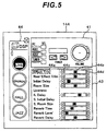
- Fig. 5 is a diagram showing an example of a display on a screen of the display device 144 controlled by the display controller 143.
- a DSP mode selection window 44 is displayed at the left side on the screen of the display device 144.
- a basic parameter setting window 41 is displayed at the upper right side on the screen of the display device 144, and a DSP parameter setting window 43 is displayed under the basic parameter setting window 41.
- the settings of parameters, the tuner 17, and volume are displayed the settings of parameters, the tuner 17, and volume, all of which can be set in the audio device 100 and an input line selected.
- DSP mode selection window 44 are displayed DSP modes: "LIVE”, “CHURCH”, “HALL”, and “JAZZ”, all of which can also be selected in the audio device 100.
- the display corresponding to the selected mode is highlighted (blackened in the drawing). The highlight of the selected mode may be done by using different colors from unselected modes, enlarging the size of the display, flashing the display or the like.
- the DSP parameter setting window 43 displays status of various parameters valid in the selected DSP mode. In the drawing is displayed status of parameters for: effect trim, rear effect trim, initial delay, room size, S. delay, S. room size, reverb time, reverb level and reverb delay. Status of parameters for "liveness” and "S. initial delay” is not displayed because these parameters have no use in the selected "LIVE" DSP mode.
- the parameters displayed in the DSP parameter setting window 43 cannot be set on the control panel 6 of the audio device 100 and are included in the second group of parameters. These second group of parameters allows a user to set details of the mode selected by the first group of parameters in detail. In this embodiment, only using the PC 14 can modify detailed settings that specify the parameter set by the control panel 6. For example, a user can select one of the DSP modes with both of the audio device 100 and the PC 14, while the user can modify the DSP parameters only with the PC 14.
- a volume condition display also functions as a volume control switch.
- a user can set a parameter by manipulating a corresponding control switch displayed on the screen of the display device 144 with the keyboard 145, the mouse 146 and/or other pointing device. Therefore, the display device 144 not only displays status of various parameters but also functions as a graphical user Interface (GUI) that allows user to set displayed parameters.
- GUI graphical user Interface
- text 44a is a name of a parameter
- a mark 44b shows current status of the parameter by its position
- clickable button 44c and 44d allow a user to change the parameter by moving the mark 44b left or right.
- a user can set the parameter at a specific value by clicking either clickable button 44c or 44d to move the mark 44b left or right to a position corresponding to the value that the user wants to set.
- Parameters set by a user with the GUI displayed in the display device 144 are transmitted to the audio device 100 through the interface 141.
- the modified parameter is transmitted to the audio device 100 via the interface 141.
- the audio amplifier 4 performs a process to audio signals input from the input selector 3 based on the modified parameter transmitted from the PC 14 as well as other parameters. Then the processed audio signals are output from the speaker output 5 to be reproduced by loudspeakers.
- parameters e.g., volume control
- parameters that can be set on the control panel 6 can also be set on the screen of the display device 144 with the GUI. That is, parameters that can be set on the control panel 6 can be set both in the audio device 100 and the PC 14.
- volume parameter When a user sets volume of a sound with the master volume control dial 6f on the control panel 6 of the audio device 100, the value of volume parameter is transmitted to the audio amplifier 4 to process volume control to a sound reproduced, and in addition the value is transmitted to the PC 14 via the bus 11, the PC connector 13 and the interface 12.
- the display controller 142 of the PC 14 receives the value, and thereby controls the display device 144 to display status of volume parameter corresponding to the received value.
- the display device 144 displays status of parameters even if settings are performed with the control panel 6 of the audio device. Therefore, the user can check all parameter settings of the audio device 100 by looking at the display of the display device 144 of the PC 14.
- the contents of the display on the display device 142 (hereinafter called display style) based on the control of the display controller 144 are not limited to those shown in Fig. 5.
- the display controller 144 controls the display device 142 by the control program read out by the reading device 143, therefore the user can change the display style by using a CD-ROM storing other type of the control program.
- locations and areas of the above-described three windows 41 43 and 44 may be changed.
- parameters may be displayed in text data (i.e., raw numbers).
- a user may use the control program enabling many kinds of display style beforehand and select one kind of display style with the keyboard 145 or the GUI displayed on the display device 144.
- a user may use a control program that allows the user to change sizes and locations of three windows 41, 43 and 44 by manipulating the keyboard 145 and/or the pointing device 146. By using those kinds of programs, a user can customize the display style into a style wherein the user can easily check the parameters.
- Fig. 6 and Fig. 7 are diagrams showing other examples of a display on a screen of the display device 144 controlled by the display controller 143.
- a picture 6' designed to be similar to the appearance of the control panel 6 of the audio device 100.
- the user should manipulate the DSP switch 6b and the DSP/tuner setting up-down switches 6d and 6e.
- the user should manipulate switches 6b', 6d' and 6e' in the picture 6' corresponding to the DSP switch 6b and the DSP/tuner setting up-down switches 6d and 6e.
- the selected mode "LIVE" is displayed in an area 8d' corresponding to the multi-function display 8d.
- a group of detailed parameters applicable in the selected DSP mode a display similar to the DSP parameter window 44 in Fig. 5, is displayed under the picture 6'.
- a user can close the DSP parameter window 44 by clicking an escape mark 44e to return to the display shown in Fig. 6 wherein only the picture 6' is displayed.
- the display style may be tree-style like the above.
- Fig. 8 is a flow chart of a main process of the audio system 1 when a user set the DSP parameters of the audio device 100 from the PC 14. In this flow, the displays shown in Fig. 6 arid Fig. 7 are displayed on the screen of the display device 144.
- the main process of the audio system 1 is started by turning on power switches of the audio device 100 and the PC 14, both of them being connected to each other.
- Step Sa1 upon an input of a command of the user to start the GUI functions, the reading device 143 reads out the control program stored in a CD-ROM or the like. Then the display controller 142 performs the process according to the program.
- Step Sa2 the basic parameters (the picture 6') shown in Fig. 6 are displayed on the screen of the display device 144.
- Step Sa3 the display controller 142 detects a selection of the DSP mode made by the user. When the user does not make the selection, the process returns to the Step Sa2. When the selection is detected, the process proceeds to the next Step Sa4.
- Step Sa4 the group of detailed parameters applicable in the selected DSP mode is displayed as shown in Fig. 7.
- Step Sa5 the display controller 142 detects clicking of the escape mark 44e by the pointing device 146 or the like. When the clicking is detected, the DSP parameter window 44 is closed, and the process returns to the Step Sa2. Otherwise, the process proceeds to the Step Sa6.
- the display controller 142 modifies a value of a parameter based on a manipulation of the user.
- Step Sa7 the setting of the parameter modified at the Step Sa6 is transmitted to the audio device 100, wherein audio signals are processed based on the setting made by the user. Then, the process returns to the Step Sa5.
- the audio system 1 allows a user to set a multiplicity of parameters from the PC 14 to the audio device 100, such as a selection of the DSP mode, detailed setting of parameters for the selected DSP mode, or the like, although the control panel 6 of the audio device 100 has switches just for the basic parameters. That is, according to the embodiment, a multiplicity of parameters can be set without a front panel space for many switches assigned to the parameters, therefore the audio device 100 can be easily miniaturized.
- the display device 144 can display status of all the parameters on its screen, a user can check all the parameters by looking just at the screen of the display device 144. Therefore, the audio system 1 has two user interfaces; the control panel 6 of the audio device and the display device 144 of the PC 14, a user can check the status with just the display device 144.
- the user can change the contents of the screen displayed on the display device 144 easily by changing the control program read out by the reading device 143 or with the manipulation of the keyboard 145 or the pointing device 146. Therefore, customization of the display style according to the preference allows the user to set the parameters for the audio device 100 easily.
- a user can set the basic parameters by manipulating the control panel 6 of the audio device 100 without connecting the audio device 100 to the PC 14. Therefore, the user can selectively disconnect the PC 14 from the audio device 100 when the detailed settings of the parameters are not necessary, or connect the PC 14 to the audio device 100 when the detailed settings of the parameters are necessary.
- a device connected to the audio device 100 is not limited to a personal computer.
- Fig. 9 is a block diagram showing a structure of an audio system according to a modified embodiment of the invention.
- the audio device 100 is connected to a DVD player 90.
- the DVD player 90 is further connected to a display 92 such as a television set, a monitor or the likes, wherein the setting windows are displayed to function as the GUI.
- a controller 94 built in the DVD player 90 performs similar functions as the display controller 142 of the PC 14 based on a control program read out from a DVD-ROM.
- a remote controller 93 that can set both basic parameters and detailed parameters is a pointing device for manipulating GUI displayed on a screen of the display 92.
- the audio device 100 or the DVD player 90 has a receiver 95 for receiving the setting information transmitted from the remote controller 93.
- the audio device 100 performs a digital sound-field process to audio signals based on the received setting information as well as transmits the setting information to the DVD player 90.
- the DVD player 90 receives the setting information, and the controller 94 therein controls the display of the display 92 based on the received setting information.
Landscapes
- Engineering & Computer Science (AREA)
- Computer Networks & Wireless Communication (AREA)
- Signal Processing (AREA)
- Stereophonic System (AREA)
- Control Of Amplification And Gain Control (AREA)
- Circuit For Audible Band Transducer (AREA)
- User Interface Of Digital Computer (AREA)
Applications Claiming Priority (2)
| Application Number | Priority Date | Filing Date | Title |
|---|---|---|---|
| JP16899699A JP2000357035A (ja) | 1999-06-15 | 1999-06-15 | オーディオシステム |
| JP16899699 | 1999-06-15 |
Publications (3)
| Publication Number | Publication Date |
|---|---|
| EP1061658A2 true EP1061658A2 (fr) | 2000-12-20 |
| EP1061658A3 EP1061658A3 (fr) | 2003-05-21 |
| EP1061658B1 EP1061658B1 (fr) | 2007-09-12 |
Family
ID=15878429
Family Applications (1)
| Application Number | Title | Priority Date | Filing Date |
|---|---|---|---|
| EP00111953A Expired - Lifetime EP1061658B1 (fr) | 1999-06-15 | 2000-06-15 | Système audio avec interface graphique utilisateur |
Country Status (3)
| Country | Link |
|---|---|
| EP (1) | EP1061658B1 (fr) |
| JP (1) | JP2000357035A (fr) |
| DE (1) | DE60036331T2 (fr) |
Cited By (1)
| Publication number | Priority date | Publication date | Assignee | Title |
|---|---|---|---|---|
| US20100306667A1 (en) * | 2004-01-15 | 2010-12-02 | Yamaha Corporation | Remote control method of external devices |
Families Citing this family (1)
| Publication number | Priority date | Publication date | Assignee | Title |
|---|---|---|---|---|
| JP2002313071A (ja) * | 2001-04-12 | 2002-10-25 | Sony Corp | オーディオ装置、設定情報編集装置、プログラム、オーディオ装置の動作制御方法及び設定情報編集方法 |
Family Cites Families (3)
| Publication number | Priority date | Publication date | Assignee | Title |
|---|---|---|---|---|
| JPH0757442A (ja) * | 1993-08-18 | 1995-03-03 | Sony Corp | 電子機器 |
| WO1996012255A1 (fr) * | 1994-10-12 | 1996-04-25 | Technical Maintenance Corporation | Systeme de reproduction audio-visuelle numerique intelligent |
| US5625608A (en) * | 1995-05-22 | 1997-04-29 | Lucent Technologies Inc. | Remote control device capable of downloading content information from an audio system |
-
1999
- 1999-06-15 JP JP16899699A patent/JP2000357035A/ja active Pending
-
2000
- 2000-06-15 DE DE60036331T patent/DE60036331T2/de not_active Expired - Lifetime
- 2000-06-15 EP EP00111953A patent/EP1061658B1/fr not_active Expired - Lifetime
Cited By (2)
| Publication number | Priority date | Publication date | Assignee | Title |
|---|---|---|---|---|
| US20100306667A1 (en) * | 2004-01-15 | 2010-12-02 | Yamaha Corporation | Remote control method of external devices |
| US8935444B2 (en) | 2004-01-15 | 2015-01-13 | Yamaha Corporation | Remote control method of external devices |
Also Published As
| Publication number | Publication date |
|---|---|
| EP1061658A3 (fr) | 2003-05-21 |
| EP1061658B1 (fr) | 2007-09-12 |
| DE60036331D1 (de) | 2007-10-25 |
| JP2000357035A (ja) | 2000-12-26 |
| DE60036331T2 (de) | 2008-06-12 |
Similar Documents
| Publication | Publication Date | Title |
|---|---|---|
| EP2485484B1 (fr) | Système de cinéma maison, dispositif de lecture audio/vidéo, dispositif de commande d'émission audio, et procédé de commande de volume | |
| US6490009B1 (en) | Electronic device for selecting inputs and outputs of audio-visual equipment | |
| US5255180A (en) | Control apparatus for systematically operating audio and/or video sets | |
| US7298424B2 (en) | Display apparatus and method of controlling the same | |
| EP1061655B1 (fr) | Système audio avec processeur numérique de signaux , et procedé de commande | |
| US7133730B1 (en) | Audio apparatus, controller, audio system, and method of controlling audio apparatus | |
| EP1061774B1 (fr) | Système audio avec processeur de champ sonore | |
| EP1061658A2 (fr) | Sysème audio avec interface graphique utilisateur | |
| US6697687B1 (en) | Image display apparatus having audio output control means in accordance with image signal type | |
| JP3806610B2 (ja) | ボリューム調整装置、ボリューム調整方法、及び、プログラム | |
| EP0806758A1 (fr) | Dispositif d'accompagnement sans fil | |
| JP3208256B2 (ja) | 音声処理出力装置 | |
| JP4613058B2 (ja) | 音響装置、その制御方法、制御プログラムおよび記録媒体 | |
| EP1061657A2 (fr) | Appareil audio et procedé de commande d'un système audio | |
| JPH11175457A (ja) | 車載機器情報表示方法、車載用情報処理装置及び自動車 | |
| JP3633751B2 (ja) | 表示回路 | |
| JP3975233B2 (ja) | オーディオ機器および音声出力制御方法 | |
| JP2006186571A (ja) | オーディオ装置およびその制御方法 | |
| JP4747830B2 (ja) | オーディオ装置及び出力切替え方法 | |
| JP2005032106A (ja) | 情報出力装置及び情報出力方法 | |
| JP4431033B2 (ja) | 音響装置、その制御方法、制御プログラムおよび記録媒体 | |
| JP2001333500A (ja) | Av機器及びav機器の音声入力方法 | |
| JP2000276833A (ja) | 表示変更可能なオーディオシステム | |
| CA2175961A1 (fr) | Appareil d'accompagnement sans fil | |
| KR20060118496A (ko) | 멀티모드 디스플레이 장치의 오디오 정보 디스플레이 |
Legal Events
| Date | Code | Title | Description |
|---|---|---|---|
| PUAI | Public reference made under article 153(3) epc to a published international application that has entered the european phase |
Free format text: ORIGINAL CODE: 0009012 |
|
| AK | Designated contracting states |
Kind code of ref document: A2 Designated state(s): AT BE CH CY DE DK ES FI FR GB GR IE IT LI LU MC NL PT SE |
|
| AX | Request for extension of the european patent |
Free format text: AL;LT;LV;MK;RO;SI |
|
| PUAL | Search report despatched |
Free format text: ORIGINAL CODE: 0009013 |
|
| AK | Designated contracting states |
Designated state(s): AT BE CH CY DE DK ES FI FR GB GR IE IT LI LU MC NL PT SE |
|
| AX | Request for extension of the european patent |
Extension state: AL LT LV MK RO SI |
|
| 17P | Request for examination filed |
Effective date: 20031121 |
|
| AKX | Designation fees paid |
Designated state(s): DE FR GB |
|
| 17Q | First examination report despatched |
Effective date: 20040127 |
|
| GRAP | Despatch of communication of intention to grant a patent |
Free format text: ORIGINAL CODE: EPIDOSNIGR1 |
|
| RTI1 | Title (correction) |
Free format text: AUDIOSYSTEM MIT GRAFISCHER BENUTZERSCHNITTSTELLE |
|
| RAP1 | Party data changed (applicant data changed or rights of an application transferred) |
Owner name: YAMAHA CORPORATION |
|
| GRAS | Grant fee paid |
Free format text: ORIGINAL CODE: EPIDOSNIGR3 |
|
| GRAA | (expected) grant |
Free format text: ORIGINAL CODE: 0009210 |
|
| AK | Designated contracting states |
Kind code of ref document: B1 Designated state(s): DE FR GB |
|
| REG | Reference to a national code |
Ref country code: GB Ref legal event code: FG4D |
|
| REF | Corresponds to: |
Ref document number: 60036331 Country of ref document: DE Date of ref document: 20071025 Kind code of ref document: P |
|
| ET | Fr: translation filed | ||
| PLBE | No opposition filed within time limit |
Free format text: ORIGINAL CODE: 0009261 |
|
| STAA | Information on the status of an ep patent application or granted ep patent |
Free format text: STATUS: NO OPPOSITION FILED WITHIN TIME LIMIT |
|
| 26N | No opposition filed |
Effective date: 20080613 |
|
| PGFP | Annual fee paid to national office [announced via postgrant information from national office to epo] |
Ref country code: GB Payment date: 20140611 Year of fee payment: 15 |
|
| PGFP | Annual fee paid to national office [announced via postgrant information from national office to epo] |
Ref country code: DE Payment date: 20140611 Year of fee payment: 15 |
|
| PGFP | Annual fee paid to national office [announced via postgrant information from national office to epo] |
Ref country code: FR Payment date: 20140609 Year of fee payment: 15 |
|
| REG | Reference to a national code |
Ref country code: DE Ref legal event code: R119 Ref document number: 60036331 Country of ref document: DE |
|
| GBPC | Gb: european patent ceased through non-payment of renewal fee |
Effective date: 20150615 |
|
| REG | Reference to a national code |
Ref country code: FR Ref legal event code: ST Effective date: 20160229 |
|
| PG25 | Lapsed in a contracting state [announced via postgrant information from national office to epo] |
Ref country code: DE Free format text: LAPSE BECAUSE OF NON-PAYMENT OF DUE FEES Effective date: 20160101 Ref country code: GB Free format text: LAPSE BECAUSE OF NON-PAYMENT OF DUE FEES Effective date: 20150615 |
|
| PG25 | Lapsed in a contracting state [announced via postgrant information from national office to epo] |
Ref country code: FR Free format text: LAPSE BECAUSE OF NON-PAYMENT OF DUE FEES Effective date: 20150630 |