EP1061768B1 - Transformateur,dispositif de haut-parleur et système de haut-parleur - Google Patents
Transformateur,dispositif de haut-parleur et système de haut-parleur Download PDFInfo
- Publication number
- EP1061768B1 EP1061768B1 EP00112711A EP00112711A EP1061768B1 EP 1061768 B1 EP1061768 B1 EP 1061768B1 EP 00112711 A EP00112711 A EP 00112711A EP 00112711 A EP00112711 A EP 00112711A EP 1061768 B1 EP1061768 B1 EP 1061768B1
- Authority
- EP
- European Patent Office
- Prior art keywords
- loudspeaker
- transformer
- bobbin
- horn
- primary winding
- Prior art date
- Legal status (The legal status is an assumption and is not a legal conclusion. Google has not performed a legal analysis and makes no representation as to the accuracy of the status listed.)
- Expired - Lifetime
Links
Images


Classifications
-
- H—ELECTRICITY
- H04—ELECTRIC COMMUNICATION TECHNIQUE
- H04R—LOUDSPEAKERS, MICROPHONES, GRAMOPHONE PICK-UPS OR LIKE ACOUSTIC ELECTROMECHANICAL TRANSDUCERS; ELECTRIC HEARING AIDS; PUBLIC ADDRESS SYSTEMS
- H04R17/00—Piezoelectric transducers; Electrostrictive transducers
-
- H—ELECTRICITY
- H04—ELECTRIC COMMUNICATION TECHNIQUE
- H04R—LOUDSPEAKERS, MICROPHONES, GRAMOPHONE PICK-UPS OR LIKE ACOUSTIC ELECTROMECHANICAL TRANSDUCERS; ELECTRIC HEARING AIDS; PUBLIC ADDRESS SYSTEMS
- H04R3/00—Circuits for transducers
Definitions
- the present invention relates to transformers, loudspeaker devices, loudspeaker networks, and loudspeaker systems, and more specifically relates to a transformer included in a piezoelectric loudspeaker, and to a loudspeaker device, a loudspeaker network, and a loudspeaker system that include the above-described transformer.
- a transformer for a conventional piezoelectric loudspeaker is constructed such that a primary winding and a secondary winding are wound around a bobbin and a core is inserted into the bobbin.
- the transformer is expensive as well as heavy due to the use of the core. Accordingly, the removal of the core has been contemplated to produce an inexpensive and light-weight transformer. However, the removal of the core decreases the magnetic coupling strength between the primary winding and the secondary winding. Moreover, to reduce the size of the piezoelectric loudspeaker, it is desirable to provide another member, such as a portion of the loudspeaker, within the above-described transformer of the conventional piezoelectric loudspeaker. These points also apply to a loudspeaker device, a loudspeaker network, and a loudspeaker system that include the transformer for the conventional piezoelectric loudspeaker.
- EP 0 264110 A discloses an electromagnetic arrangement, especially an electromagnetic winding with conductor turns which are electrically insulated from one another, are electrically insulated with respect to one another and have the form of an electrically conductive film.
- the film may be a metal coating on an electrically insulated plastic film or may consist of electrically conductive plastic with an insulating layer between the individual turns of the winding.
- US-A-4,461,931 discloses an electrostatic loudspeaker system includes a transformer whose secondary winding is connected to the conductive plates of an electrostatic loudspeaker and whose primary winding is energized by an audio input signal through a frequency response equalizing network which includes an autotransformer winding as well as resistive and capacitive elements.
- the autotransformer winding is connected in parallel with the primary winding, one audio input terminal is directly connected to one end of the autotransformer winding, at least one tap of the autotransformer winding is connected through a resistive element to the other audio input terminal and the other end of the autotransformer winding is connected to the other audio input terminal through a capacitive element.
- preferred embodiments of the present invention provide a loudspeaker device, a loudspeaker network, and a loudspeaker system which include a transformer that is inexpensive, compact, and lightweight, and that has strong magnetic coupling between a primary winding and a secondary winding, and which has another member disposed therein.
- a transformer including a bobbin having a cavity, a primary winding wound around the bobbin, and a secondary winding wound around the bobbin and magnetically coupled with the primary winding.
- one of the primary winding and the secondary winding is divided into at least two portions which include a portion wound at the inside and a portion wound at the outside, at least a portion of the other one of the primary winding and the secondary winding is wound between said at least two portions obtained by dividing the one of the primary winding and the secondary winding, and at least a portion of the cavity of the bobbin is used as a space to accommodate another member therein.
- a loudspeaker device includes a transformer as described in the previous paragraph, and a loudspeaker, connected to the transformer, and including a sound-producing body having a piezoelectric body.
- the loudspeaker device at least a portion of the loudspeaker is provided in the cavity of the bobbin.
- the loudspeaker has a horn for conducting sound waves transmitted from the sound-producing body, one end of the horn is inserted into the cavity of the bobbin, and the bobbin of the transformer is mounted on the horn.
- a loudspeaker network includes a transformer having the features of the preferred embodiment described above and an impedance network connected to the transformer.
- a loudspeaker system includes a loudspeaker device according to an embodiment described above, and a loudspeaker network according to the preferred embodiment described above.
- the transformer of the loudspeaker device includes the transformer of the loudspeaker network.
- the transformer Since there is no core used in the transformer, the transformer is inexpensive as well as lightweight.
- the magnetic coupling between the primary winding and the secondary winding of the transformer is stronger than a transformer constructed by winding the entire primary winding and the winding the entire secondary.
- the transformer according to embodiments of the present invention since a portion of the cavity of the bobbin is used as a space for having another member disposed therein, another member, such as an end portion of the horn of the loudspeaker, can be disposed therein.
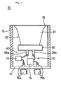
- FIG. 1 is an illustration showing one example of a loudspeaker system according to the present invention.
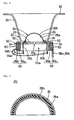
- Fig. 2 is an illustration showing a loudspeaker device of the loudspeaker system.
- a loudspeaker system 10 shown in Fig. 1 preferably includes a substantially cylindrical casing 12 made of synthetic resin, or other suitable material. One end of the casing 12 is open while the other end has a disk-shaped lid 14 adhered thereto.
- the casing 12 has a piezoelectric loudspeaker 20 mounted therein as a tweeter.
- the piezoelectric loudspeaker 20 includes a disk-shaped supporting member 22 as shown in Fig. 2 .
- a hole 22a, serving as a so-called "air vent” is provided at the approximate center of the supporting member 22.
- One major surface of the supporting member 22 has a substantially hemispherical vibrator 24 with a diameter of about 20 mm attached thereto.
- the vibrator 24 functions as a sound-producing body and includes a substantially hemispherical vibrating body 26 which is made of a piezoelectric material, such as a piezoelectric ceramic, or other suitable piezoelectric material, polarized in the thickness direction, as shown in Fig. 3 .
- Electrodes 28a and 28b are provided on the internal surface and external surface of the vibrator 24, respectively.
- input terminals 30a and 30b each have one end thereof soldered to the electrodes 28a and 28b of the vibrator 24, respectively. Furthermore, a horn 32 made of a synthetic resin, or other suitable material, is mounted around the supporting member 22.
- the horn 32 is configured so that the width thereof gradually increases from one end 34 towards the other end 36.
- the end 34 of the horn 32 includes a step and the other end 36 of the horn 32 includes a flange.
- the end 34 of the horn 32 is adhered to the surrounding of the supporting member 22, thus securing the input terminals 30a and 30b between the end 34 of the horn 32 and the surrounding of the support member 22, as shown in Fig. 2 .
- the other end 36 of the horn 32 is adhered to one end of the casing 12 as shown in Fig. 1 , and supports the piezoelectric loudspeaker 20 in the casing 12. In this piezoelectric loudspeaker 20, by inputting a signal across the input terminals 30a and 30b, the vibrator 24 vibrates, and a sound is produced from the horn 32.
- the loudspeaker system 10 includes a loudspeaker network 40.
- the loudspeaker network 40 includes a transformer 50 and an impedance network 70.
- the transformer 50 includes a substantially cylindrical bobbin 52 made of a synthetic resin, or other suitable material.
- the bobbin 52 has a cavity 52a in the approximate center thereof.
- the nose of the end 34 of the horn 32 of the piezoelectric loudspeaker 20 is inserted into the cavity 52a of the bobbin 52.
- the bobbin 52 is fixedly adhered around the end 34 of the horn 32.
- not only the end 34 of the horn 32 but also the supporting member 22 of the piezoelectric loudspeaker 20 and middle portions of the input terminals 30a and 30b are provided in the cavity 52a of the bobbin 52.
- a primary winding 54 and a secondary winding 56 are wound around this bobbin 52.
- the secondary winding 56 is divided into two portions 56a and 56b.
- the portion 56a of the secondary winding 56, the primary winding 54, and the portion 56b of the secondary winding 56 are wound in that order around the bobbin 52, such that the primary winding 54 is sandwiched between portions 56a and 56b of the secondary winding 56.
- one end of the portion 56a is connected to the input terminal 30a of the piezoelectric loudspeaker 20
- the other end of the portion 56a is connected to one end of the portion 56b
- the other end of the portion 56b is connected to the input terminal 30b of the piezoelectric loudspeaker 20.
- the ends of the secondary winding 56 are connected to the corresponding input terminals 30a and 30b of the piezoelectric loudspeaker 20.
- the ends of the primary winding 54 are connected to corresponding terminals 58a and 58b. These terminals 58a and 58b are mounted via an insulating tape 60 on the portion 56b of the secondary winding 56.
- the loudspeaker device is constructed by combining the piezoelectric loudspeaker 20 and the transformer 50.
- the impedance network 70 includes a capacitor 72 of about 2 ⁇ F and a resistor 74 of about 6.7 k ⁇ , or other suitable capacitance and resistance.
- One end of the capacitor 72 and one end of the resistor 74 are connected to the two terminals 58a and 58b of the transformer 50, respectively.
- the other end of the capacitor 72 and the other end of the resistor 74 are connected to two external terminals 76a and 76b, respectively. These external terminals 76a and 76b are mounted so as to penetrate the lid 14 of the casing 12.
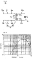
- this loudspeaker system 10 includes a circuit shown in Fig. 4 .
- the loudspeaker system 10 is inexpensive as well as lightweight.
- the magnetic coupling between the primary winding 54 and the secondary winding 56 is stronger than the magnetic coupling between a primary winding and a secondary winding of a transformer constructed by winding the primary winding and the secondary winding in that order, such that the primary winding is not sandwiched between two portions of the secondary winding.
- the cavity 52a of the bobbin 52 of the transformer 50 is effectively used as a space for disposing the supporting member 22 and the input terminals 30a and 30b of the piezoelectric loudspeaker 20, and the end 34 of the horn 32.
- this loudspeaker system 10 as shown by frequency characteristics of the boost ratio of the loudspeaker network 40 in Fig. 5 , the boost ratio is high in the high frequency band. Accordingly, this loudspeaker system 10 produces an outstanding tweeter because high sound pressure is obtained from the piezoelectric loudspeaker 20 in the high frequency band.
- the frequency characteristics of the impedance of the loudspeaker network 40 as shown in Fig. 6 illustrate that the impedance is high at portions of the low frequency band. Accordingly, when this loudspeaker system 10 is connected in parallel with another loudspeaker, such as a woofer, this loudspeaker system 10 performs very well because it does not practically affect a signal in the low frequency band.
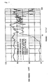
- Frequency characteristics of sound pressures concerning this loudspeaker system 10, another loudspeaker system, and the loudspeaker system obtained by connecting these systems in parallel are shown in Fig. 7 . According to the frequency characteristics shown in Fig. 7 , the other loudspeaker system does not have a very high sound pressure in the high frequency band. However, by connecting the loudspeaker system 10 in parallel with the other loudspeaker system, the sound pressure is increased in the high frequency band while it is not substantially affected in the low frequency band.
- the end 34 of the horn 32 of the piezoelectric loudspeaker 20 is a node of the piezoelectric loudspeaker 20. Since the loudspeaker device is constructed by mounting the transformer 50 at the end 34, a loudspeaker device having a compact structure is produced, in which the transformer 50 does not substantially affect the vibration of the piezoelectric loudspeaker 20 and the space of the air-core unit of the transformer 50 (the cavity 52a) can be effectively utilized.
- the transformer 50 since a core is not used in the transformer 50, the inductance of the transformer 50 is greatly reduced, and the desired inductance is obtained in the high frequency band. Accordingly, the transformer 50 is well-suited for use in the loudspeaker network 40.
- FIG. 8 is a perspective view showing another preferred embodiment of the loudspeaker system according to the present invention.
- a loudspeaker system 10 shown in Fig. 8 has the piezoelectric loudspeaker 20 and the loudspeaker network 40, along with a midrange 90 and a woofer 100, mounted in one casing 80.
- the secondary winding 56 can be wound between two portions of the primary winding 54.
- portions obtained by dividing each of the primary winding 54 and the secondary winding 56 into at least two portions may be alternately wound from among the primary winding portions and the secondary winding portions.
- the supporting member 22 and the input terminals 30a and 30b of the piezoelectric loudspeaker 20 and the one end of the horn 32 are provided within the cavity 52a of the bobbin 52 of the transformer 50, other members may also be disposed therein.
- the impedance network 70 including the capacitor 72 and the resistor 74 is provided, another impedance network may be used.
Landscapes
- Physics & Mathematics (AREA)
- Engineering & Computer Science (AREA)
- Acoustics & Sound (AREA)
- Signal Processing (AREA)
- Piezo-Electric Transducers For Audible Bands (AREA)
- Audible-Bandwidth Dynamoelectric Transducers Other Than Pickups (AREA)
- Details Of Audible-Bandwidth Transducers (AREA)
- Circuit For Audible Band Transducer (AREA)
- Coils Or Transformers For Communication (AREA)
Claims (11)
- Transformateur (50) comprenant :une bobine (52) ;un enroulement primaire (54) enroulé autour de ladite bobine (52) ; etun enroulement secondaire (56) enroulé autour de ladite bobine (52) et magnétiquement couplé audit enroulement primaire (54) ;caractérisé en ce queladite bobine (52) comporte une cavité (52a) ;un enroulement (56) parmi ledit enroulement primaire (54) et ledit enroulement secondaire (56) est divisé en au moins deux parties (56a, 56b) qui comprennent une partie (56a) enroulée au niveau d'une région intérieure du transformateur (50) et une partie (56b) enroulée au niveau d'une région extérieure du transformateur (50) ; etau moins une partie de l'autre enroulement (54) parmi ledit enroulement primaire (54) et ledit enroulement secondaire (56) est enroulée entre lesdites au moins deux parties (56a, 56b).
- Transformateur (50) selon la revendication 1, dans lequel au moins une partie de ladite cavité (52a) de ladite bobine (52) est utilisée comme espace pour recevoir un élément de support.
- Dispositif de haut-parleur (10) comprenant :un transformateur (50) selon la revendication 1 ; etun haut-parleur (20), relié audit transformateur (50), et comprenant un corps de production sonore (26) comportant un corps piézoélectrique.
- Dispositif de haut-parleur (10) selon la revendication 3, dans lequel au moins une partie dudit haut-parleur (20) se trouve dans ladite cavité (52a) de ladite bobine (52).
- Dispositif de haut-parleur (10) selon la revendication 3 ou 4, dans lequel ledit haut-parleur (20) comprend un élément de support (22), et ledit corps de production sonore (26) est monté sur ledit élément de support (22).
- Dispositif de haut-parleur (10) selon la revendication 5, dans lequel ledit élément de support (22) est en forme de disque et comprend un trou (22a) dans une partie centrale approximative de celui-ci.
- Dispositif de haut-parleur (10) selon l'une des revendications 3 à 6, dans lequel ledit haut-parleur (20) comprend un pavillon acoustique (32) pour conduire des ondes sonores transmises depuis ledit corps de production sonore (26), une partie d'extrémité dudit pavillon acoustique (32) étant introduite dans ladite cavité (52a) de ladite bobine (52), et ladite bobine (52) dudit transformateur (50) étant montée sur ledit pavillon acoustique (32).
- Dispositif de haut-parleur (10) selon la revendication 7, dans lequel ledit pavillon acoustique (32) est monté sur ledit élément de support (22).
- Dispositif de haut-parleur (10) selon l'une des revendications 3 à 8, dans lequel ledit haut-parleur (20) comprend en outre une pluralité de bornes d'entrée (30a, 30b) reliées audit corps de production sonore (26), et chaque borne de la pluralité de bornes d'entrée (30a, 30b) comporte une partie disposée entre ledit pavillon acoustique (32) et ledit élément de support (22).
- Réseau de haut-parleur (40) comprenant :un transformateur (50) selon la revendication 1 ou 2 ; etun réseau d'impédance (70) relié audit transformateur (50).
- Système de haut-parleur (10) comprenant :un dispositif de haut-parleur (10) selon l'une des revendications 3 à 9; etun réseau d'impédance (70) relié audit transformateur (50).
Applications Claiming Priority (4)
| Application Number | Priority Date | Filing Date | Title |
|---|---|---|---|
| JP17218599 | 1999-06-18 | ||
| JP17218599 | 1999-06-18 | ||
| JP2000064948 | 2000-03-09 | ||
| JP2000064948A JP3692897B2 (ja) | 1999-06-18 | 2000-03-09 | スピーカ装置およびスピーカシステム |
Publications (3)
| Publication Number | Publication Date |
|---|---|
| EP1061768A2 EP1061768A2 (fr) | 2000-12-20 |
| EP1061768A3 EP1061768A3 (fr) | 2003-04-09 |
| EP1061768B1 true EP1061768B1 (fr) | 2011-02-09 |
Family
ID=26494634
Family Applications (1)
| Application Number | Title | Priority Date | Filing Date |
|---|---|---|---|
| EP00112711A Expired - Lifetime EP1061768B1 (fr) | 1999-06-18 | 2000-06-15 | Transformateur,dispositif de haut-parleur et système de haut-parleur |
Country Status (4)
| Country | Link |
|---|---|
| US (1) | US6718040B1 (fr) |
| EP (1) | EP1061768B1 (fr) |
| JP (1) | JP3692897B2 (fr) |
| DE (1) | DE60045605D1 (fr) |
Families Citing this family (4)
| Publication number | Priority date | Publication date | Assignee | Title |
|---|---|---|---|---|
| JP3894856B2 (ja) * | 2002-07-19 | 2007-03-22 | 松下電器産業株式会社 | スピーカ |
| US8917896B2 (en) | 2009-09-11 | 2014-12-23 | Bose Corporation | Automated customization of loudspeakers |
| US9049519B2 (en) | 2011-02-18 | 2015-06-02 | Bose Corporation | Acoustic horn gain managing |
| BR112019007960A2 (pt) * | 2016-10-28 | 2019-07-02 | Sony Corp | transdutor eletroacústico e aparelho transdutor eletroacústico. |
Family Cites Families (5)
| Publication number | Priority date | Publication date | Assignee | Title |
|---|---|---|---|---|
| NL8103095A (nl) * | 1981-06-26 | 1983-01-17 | Bernardus Gradus Peters | Elektrostatische luidspreker. |
| JPS5834699A (ja) * | 1981-08-24 | 1983-03-01 | Citizen Watch Co Ltd | 小型薄型圧電スピ−カ |
| DE3635152A1 (de) * | 1986-10-15 | 1988-04-21 | Hoegl Helmut | Elektromagnetische anordnung, insbesondere elektromagnetische wicklung |
| US4845776A (en) * | 1987-05-11 | 1989-07-04 | Electro Acustica S.A. | Piezoelectric transducer and transformer circuit |
| JP3309798B2 (ja) * | 1997-06-03 | 2002-07-29 | 株式会社村田製作所 | 圧電スピーカ用トランス |
-
2000
- 2000-03-09 JP JP2000064948A patent/JP3692897B2/ja not_active Expired - Lifetime
- 2000-06-15 DE DE60045605T patent/DE60045605D1/de not_active Expired - Lifetime
- 2000-06-15 US US09/593,376 patent/US6718040B1/en not_active Expired - Lifetime
- 2000-06-15 EP EP00112711A patent/EP1061768B1/fr not_active Expired - Lifetime
Also Published As
| Publication number | Publication date |
|---|---|
| US6718040B1 (en) | 2004-04-06 |
| EP1061768A3 (fr) | 2003-04-09 |
| EP1061768A2 (fr) | 2000-12-20 |
| JP2001061200A (ja) | 2001-03-06 |
| DE60045605D1 (de) | 2011-03-24 |
| JP3692897B2 (ja) | 2005-09-07 |
Similar Documents
| Publication | Publication Date | Title |
|---|---|---|
| KR0129547B1 (ko) | 유도형 스피커 | |
| US10777892B2 (en) | Antenna | |
| JP2566823B2 (ja) | 電気音響変換器およびスピーカ | |
| US5392358A (en) | Electrolytic loudspeaker assembly | |
| EP1037502B1 (fr) | Haut-parleur | |
| US20030174856A1 (en) | Flexible diaphragm with integrated coil | |
| US12081958B2 (en) | Coil with different windings | |
| US10979821B2 (en) | Sound generator | |
| CA2435932A1 (fr) | Transducteur electroacoustique | |
| CA2182610A1 (fr) | Transducteur electrodynamique | |
| EP1481569B1 (fr) | Membrane souple a bobine integree | |
| US5014321A (en) | Wide passband omnidirectional loudspeaker | |
| US8379898B2 (en) | Transmission facility for a hearing apparatus with film conductor shielding and naturally shielded coil | |
| KR20010034191A (ko) | 스피커장치 | |
| US3931469A (en) | Crossover network for a multi-element electrostatic loudspeaker system | |
| US6718040B1 (en) | Transformer, loudspeaker device, loudspeaker network, and loudspeaker system | |
| EP1146772A2 (fr) | Transducteur électro-acoustique et structure pour le montage d'un transducteur électro-acoustique | |
| EP2213107A1 (fr) | Membrane pour un microphone électrostatique | |
| JP7619649B2 (ja) | 静電容量型電気音響変換装置 | |
| WO1993001691A1 (fr) | Ensemble haut-parleur electrolytique | |
| JPH03250896A (ja) | 平面スピーカ | |
| US4035761A (en) | Sonar transducer having inertial inductor | |
| JPH0247627Y2 (fr) | ||
| JPH0823593A (ja) | スピーカ装置 | |
| JPH0339000A (ja) | 電気音響変換器 |
Legal Events
| Date | Code | Title | Description |
|---|---|---|---|
| PUAI | Public reference made under article 153(3) epc to a published international application that has entered the european phase |
Free format text: ORIGINAL CODE: 0009012 |
|
| 17P | Request for examination filed |
Effective date: 20000615 |
|
| AK | Designated contracting states |
Kind code of ref document: A2 Designated state(s): AT BE CH CY DE DK ES FI FR GB GR IE IT LI LU MC NL PT SE |
|
| AX | Request for extension of the european patent |
Free format text: AL;LT;LV;MK;RO;SI |
|
| PUAL | Search report despatched |
Free format text: ORIGINAL CODE: 0009013 |
|
| AK | Designated contracting states |
Kind code of ref document: A3 Designated state(s): AT BE CH CY DE DK ES FI FR GB GR IE IT LI LU MC NL PT SE |
|
| AX | Request for extension of the european patent |
Extension state: AL LT LV MK RO SI |
|
| RIC1 | Information provided on ipc code assigned before grant |
Ipc: 7H 04R 17/00 A |
|
| AKX | Designation fees paid |
Designated state(s): DE FR GB |
|
| RAP1 | Party data changed (applicant data changed or rights of an application transferred) |
Owner name: MURATA MANUFACTURING CO., LTD. |
|
| 17Q | First examination report despatched |
Effective date: 20071031 |
|
| GRAP | Despatch of communication of intention to grant a patent |
Free format text: ORIGINAL CODE: EPIDOSNIGR1 |
|
| GRAS | Grant fee paid |
Free format text: ORIGINAL CODE: EPIDOSNIGR3 |
|
| GRAA | (expected) grant |
Free format text: ORIGINAL CODE: 0009210 |
|
| AK | Designated contracting states |
Kind code of ref document: B1 Designated state(s): DE FR GB |
|
| REG | Reference to a national code |
Ref country code: GB Ref legal event code: FG4D |
|
| REF | Corresponds to: |
Ref document number: 60045605 Country of ref document: DE Date of ref document: 20110324 Kind code of ref document: P |
|
| REG | Reference to a national code |
Ref country code: DE Ref legal event code: R096 Ref document number: 60045605 Country of ref document: DE Effective date: 20110324 |
|
| PGFP | Annual fee paid to national office [announced via postgrant information from national office to epo] |
Ref country code: GB Payment date: 20110616 Year of fee payment: 12 |
|
| PLBE | No opposition filed within time limit |
Free format text: ORIGINAL CODE: 0009261 |
|
| STAA | Information on the status of an ep patent application or granted ep patent |
Free format text: STATUS: NO OPPOSITION FILED WITHIN TIME LIMIT |
|
| 26N | No opposition filed |
Effective date: 20111110 |
|
| REG | Reference to a national code |
Ref country code: DE Ref legal event code: R097 Ref document number: 60045605 Country of ref document: DE Effective date: 20111110 |
|
| GBPC | Gb: european patent ceased through non-payment of renewal fee |
Effective date: 20120615 |
|
| PG25 | Lapsed in a contracting state [announced via postgrant information from national office to epo] |
Ref country code: GB Free format text: LAPSE BECAUSE OF NON-PAYMENT OF DUE FEES Effective date: 20120615 |
|
| REG | Reference to a national code |
Ref country code: FR Ref legal event code: PLFP Year of fee payment: 17 |
|
| REG | Reference to a national code |
Ref country code: FR Ref legal event code: PLFP Year of fee payment: 18 |
|
| REG | Reference to a national code |
Ref country code: FR Ref legal event code: PLFP Year of fee payment: 19 |
|
| PGFP | Annual fee paid to national office [announced via postgrant information from national office to epo] |
Ref country code: DE Payment date: 20190619 Year of fee payment: 20 |
|
| PGFP | Annual fee paid to national office [announced via postgrant information from national office to epo] |
Ref country code: FR Payment date: 20190619 Year of fee payment: 20 |
|
| REG | Reference to a national code |
Ref country code: DE Ref legal event code: R071 Ref document number: 60045605 Country of ref document: DE |