EP1062020B1 - Sac de deshydratant s'ajustant par declic - Google Patents
Sac de deshydratant s'ajustant par declic Download PDFInfo
- Publication number
- EP1062020B1 EP1062020B1 EP98960544A EP98960544A EP1062020B1 EP 1062020 B1 EP1062020 B1 EP 1062020B1 EP 98960544 A EP98960544 A EP 98960544A EP 98960544 A EP98960544 A EP 98960544A EP 1062020 B1 EP1062020 B1 EP 1062020B1
- Authority
- EP
- European Patent Office
- Prior art keywords
- package
- adsorbent
- aperture
- liquid accumulator
- fluid flow
- Prior art date
- Legal status (The legal status is an assumption and is not a legal conclusion. Google has not performed a legal analysis and makes no representation as to the accuracy of the status listed.)
- Expired - Lifetime
Links
Images






Classifications
-
- F—MECHANICAL ENGINEERING; LIGHTING; HEATING; WEAPONS; BLASTING
- F24—HEATING; RANGES; VENTILATING
- F24F—AIR-CONDITIONING; AIR-HUMIDIFICATION; VENTILATION; USE OF AIR CURRENTS FOR SCREENING
- F24F3/00—Air-conditioning systems in which conditioned primary air is supplied from one or more central stations to distributing units in the rooms or spaces where it may receive secondary treatment; Apparatus specially designed for such systems
- F24F3/12—Air-conditioning systems in which conditioned primary air is supplied from one or more central stations to distributing units in the rooms or spaces where it may receive secondary treatment; Apparatus specially designed for such systems characterised by the treatment of the air otherwise than by heating and cooling
- F24F3/14—Air-conditioning systems in which conditioned primary air is supplied from one or more central stations to distributing units in the rooms or spaces where it may receive secondary treatment; Apparatus specially designed for such systems characterised by the treatment of the air otherwise than by heating and cooling by humidification; by dehumidification
- F24F3/1411—Air-conditioning systems in which conditioned primary air is supplied from one or more central stations to distributing units in the rooms or spaces where it may receive secondary treatment; Apparatus specially designed for such systems characterised by the treatment of the air otherwise than by heating and cooling by humidification; by dehumidification by absorbing or adsorbing water, e.g. using an hygroscopic desiccant
-
- B—PERFORMING OPERATIONS; TRANSPORTING
- B01—PHYSICAL OR CHEMICAL PROCESSES OR APPARATUS IN GENERAL
- B01D—SEPARATION
- B01D53/00—Separation of gases or vapours; Recovering vapours of volatile solvents from gases; Chemical or biological purification of waste gases, e.g. engine exhaust gases, smoke, fumes, flue gases, aerosols
- B01D53/02—Separation of gases or vapours; Recovering vapours of volatile solvents from gases; Chemical or biological purification of waste gases, e.g. engine exhaust gases, smoke, fumes, flue gases, aerosols by adsorption, e.g. preparative gas chromatography
- B01D53/04—Separation of gases or vapours; Recovering vapours of volatile solvents from gases; Chemical or biological purification of waste gases, e.g. engine exhaust gases, smoke, fumes, flue gases, aerosols by adsorption, e.g. preparative gas chromatography with stationary adsorbents
- B01D53/0407—Constructional details of adsorbing systems
- B01D53/0415—Beds in cartridges
-
- B—PERFORMING OPERATIONS; TRANSPORTING
- B01—PHYSICAL OR CHEMICAL PROCESSES OR APPARATUS IN GENERAL
- B01D—SEPARATION
- B01D53/00—Separation of gases or vapours; Recovering vapours of volatile solvents from gases; Chemical or biological purification of waste gases, e.g. engine exhaust gases, smoke, fumes, flue gases, aerosols
- B01D53/26—Drying gases or vapours
- B01D53/261—Drying gases or vapours by adsorption
-
- F—MECHANICAL ENGINEERING; LIGHTING; HEATING; WEAPONS; BLASTING
- F25—REFRIGERATION OR COOLING; COMBINED HEATING AND REFRIGERATION SYSTEMS; HEAT PUMP SYSTEMS; MANUFACTURE OR STORAGE OF ICE; LIQUEFACTION SOLIDIFICATION OF GASES
- F25B—REFRIGERATION MACHINES, PLANTS OR SYSTEMS; COMBINED HEATING AND REFRIGERATION SYSTEMS; HEAT PUMP SYSTEMS
- F25B43/00—Arrangements for separating or purifying gases or liquids; Arrangements for vaporising the residuum of liquid refrigerant, e.g. by heat
- F25B43/003—Filters
-
- B—PERFORMING OPERATIONS; TRANSPORTING
- B01—PHYSICAL OR CHEMICAL PROCESSES OR APPARATUS IN GENERAL
- B01D—SEPARATION
- B01D2257/00—Components to be removed
- B01D2257/80—Water
-
- B—PERFORMING OPERATIONS; TRANSPORTING
- B01—PHYSICAL OR CHEMICAL PROCESSES OR APPARATUS IN GENERAL
- B01D—SEPARATION
- B01D2259/00—Type of treatment
- B01D2259/45—Gas separation or purification devices adapted for specific applications
- B01D2259/4566—Gas separation or purification devices adapted for specific applications for use in transportation means
-
- B—PERFORMING OPERATIONS; TRANSPORTING
- B01—PHYSICAL OR CHEMICAL PROCESSES OR APPARATUS IN GENERAL
- B01D—SEPARATION
- B01D53/00—Separation of gases or vapours; Recovering vapours of volatile solvents from gases; Chemical or biological purification of waste gases, e.g. engine exhaust gases, smoke, fumes, flue gases, aerosols
- B01D53/02—Separation of gases or vapours; Recovering vapours of volatile solvents from gases; Chemical or biological purification of waste gases, e.g. engine exhaust gases, smoke, fumes, flue gases, aerosols by adsorption, e.g. preparative gas chromatography
- B01D53/04—Separation of gases or vapours; Recovering vapours of volatile solvents from gases; Chemical or biological purification of waste gases, e.g. engine exhaust gases, smoke, fumes, flue gases, aerosols by adsorption, e.g. preparative gas chromatography with stationary adsorbents
- B01D53/0407—Constructional details of adsorbing systems
- B01D53/0446—Means for feeding or distributing gases
-
- F—MECHANICAL ENGINEERING; LIGHTING; HEATING; WEAPONS; BLASTING
- F24—HEATING; RANGES; VENTILATING
- F24F—AIR-CONDITIONING; AIR-HUMIDIFICATION; VENTILATION; USE OF AIR CURRENTS FOR SCREENING
- F24F3/00—Air-conditioning systems in which conditioned primary air is supplied from one or more central stations to distributing units in the rooms or spaces where it may receive secondary treatment; Apparatus specially designed for such systems
- F24F3/12—Air-conditioning systems in which conditioned primary air is supplied from one or more central stations to distributing units in the rooms or spaces where it may receive secondary treatment; Apparatus specially designed for such systems characterised by the treatment of the air otherwise than by heating and cooling
- F24F3/14—Air-conditioning systems in which conditioned primary air is supplied from one or more central stations to distributing units in the rooms or spaces where it may receive secondary treatment; Apparatus specially designed for such systems characterised by the treatment of the air otherwise than by heating and cooling by humidification; by dehumidification
- F24F2003/144—Air-conditioning systems in which conditioned primary air is supplied from one or more central stations to distributing units in the rooms or spaces where it may receive secondary treatment; Apparatus specially designed for such systems characterised by the treatment of the air otherwise than by heating and cooling by humidification; by dehumidification by dehumidification only
-
- F—MECHANICAL ENGINEERING; LIGHTING; HEATING; WEAPONS; BLASTING
- F25—REFRIGERATION OR COOLING; COMBINED HEATING AND REFRIGERATION SYSTEMS; HEAT PUMP SYSTEMS; MANUFACTURE OR STORAGE OF ICE; LIQUEFACTION SOLIDIFICATION OF GASES
- F25B—REFRIGERATION MACHINES, PLANTS OR SYSTEMS; COMBINED HEATING AND REFRIGERATION SYSTEMS; HEAT PUMP SYSTEMS
- F25B2400/00—Component parts or details not otherwise provided for in this subclass
- F25B2400/03—Suction accumulators with deflectors
-
- F—MECHANICAL ENGINEERING; LIGHTING; HEATING; WEAPONS; BLASTING
- F25—REFRIGERATION OR COOLING; COMBINED HEATING AND REFRIGERATION SYSTEMS; HEAT PUMP SYSTEMS; MANUFACTURE OR STORAGE OF ICE; LIQUEFACTION SOLIDIFICATION OF GASES
- F25B—REFRIGERATION MACHINES, PLANTS OR SYSTEMS; COMBINED HEATING AND REFRIGERATION SYSTEMS; HEAT PUMP SYSTEMS
- F25B43/00—Arrangements for separating or purifying gases or liquids; Arrangements for vaporising the residuum of liquid refrigerant, e.g. by heat
- F25B43/006—Accumulators
-
- Y—GENERAL TAGGING OF NEW TECHNOLOGICAL DEVELOPMENTS; GENERAL TAGGING OF CROSS-SECTIONAL TECHNOLOGIES SPANNING OVER SEVERAL SECTIONS OF THE IPC; TECHNICAL SUBJECTS COVERED BY FORMER USPC CROSS-REFERENCE ART COLLECTIONS [XRACs] AND DIGESTS
- Y10—TECHNICAL SUBJECTS COVERED BY FORMER USPC
- Y10S—TECHNICAL SUBJECTS COVERED BY FORMER USPC CROSS-REFERENCE ART COLLECTIONS [XRACs] AND DIGESTS
- Y10S210/00—Liquid purification or separation
- Y10S210/06—Dehydrators
Definitions
- the present invention pertains to an adsorbent package adapted for use in air conditioning accumulators and receiver dryers of the type having a fluid flow line disposed therein that is connected to a filter or bleed nipple.
- Adsorbent packages are typically provided in automotive accumulators and receivers to dehydrate air and refrigerants.
- liquid accumulators for air conditioning systems such as automotive air conditioning systems, employ a sealed or closed canister which provides temporary storage for the refrigerant and the lubricating oil, and also provides for dehydration of the refrigerant.
- the liquid accumulator has a permanently sealed casing which includes a baffle which separates the liquid from the gas component, and also has a generally u-shaped pick up tube or suction tube with a bight portion which has a filtered bleed opening facing the container bottom.
- the tube also has two legs which extend upwardly toward the baffle at the top in generally, but not necessarily, parallel relationship, one end of which is open to receive an inflow of vaporized refrigerant for delivery to the suction side of the compressor by downward flow past the bottom pick up opening.
- One or more desiccant packages are normally carried on or mounted on this u-shaped tube with portions extending from the filtered pick up opening upwardly along the generally parallel' portions of the tube extending from the bight.
- the desiccant package is inserted and sealed within the accumulator prior to its permanent assembly. Accumulators of this general kind are shown in US-A-4,291,548 and 4,496,378 . In some cases, the adsorbent package is mounted directly to the filter.
- WO-A-97/38783 discloses an adsorbent package for use within the sealed canister of a liquid accumulator for an air conditioning system in which the suction tube within the canister has spaced upwardly extending legs connected by a bottom bight and in which a bleed opening in the bite is formed as a downwardly extending suction nipple terminating in a filter screen.
- the adsorbent package is formed with substantially identical first and second pouches formed of tubular porous polyester felt material with sealed upper and lower ends and containing adsorbent material.
- the pouches are joined to each other at upper flanges with the junction being located along an extension of a median line through the pouches and leaving the ends of the flanges free of attachment.
- the transverse width of the pouch flanges exceeds the spacing of the suction tube legs so that the flange end portions are splayed to receive one of the legs therebetween thereby locating the package in relation to the suction tube.
- the lower ends of the pouches define peripherally sealed openings which are received over the suction nipple for locating the lower ends of the pouches.
- the filter is provided as part of a plastic snap on assembly wherein a mounting ring or clasp grasps the fluid flow tube to provide a mount for the filter. Due to excessive vibration during use, abrasion of the normally fibrous pouch along this ring or clasping mechanism : could result in tearing or complete rupture of the package, spilling the contents of the package into the accumulator sump area.
- the liquid accumulator of the present invention may have an adsorbent package comprising a sole elongated pouch adapted for filling with desiccant or other adsorbent medium.
- a centrally located aperture is provided in the package and is surrounded by an annularly shaped rigid zone defining a heat or ultrasonic seal of the top surface of the package with the bottom package surface to thereby form a rigid mounting zone.
- the package opening is force or snap fit over a flange or the like associated with the bleed filter that is in turn connected to the bight tube of the accumulator.
- the bight tube is oriented transversely with regard to the longitudinal axis of the cylindrical housing and connects upwardly extending fluid flow tubes.
- the longitudinally disposed seam is formed along the length of the top or bottom side of the adsorbent pouch.
- This seam includes a double fabric layer area and may be formed via conventional means such as heat sealing, ultrasonic sealing, or other electronic sealing or fusing means.
- This longitudinally extending zone provides a reinforced area of the pouch that is adapted for positioning adjacent a ring like mounting clamp or the like which latter structure is commonly used to detachably mount a plastic filter to the bight tube portion.
- a pair of rigid shoulder members is formed along an intermediate portion of the unitary pouch.
- Each of the shoulder members extends from one of the width wise ends of the pouch towards the central opening.
- These rigid shoulders are generally flat and, cooperate with tucks formed along opposing sides of the unitary pouch to provide a reduced width portion of the pouch intermediate the longitudinal ends of the pouch. This reduced width portion of the pouch facilitates folding of the pouch. Additionally, when the accumulator canister is assembled, the accumulator housing will more readily slide or fit over the folded packet and this reduced or "necked-in" width dimension.
- Preliminary indications find that it is best to provide an aperture diameter in the package of from about .8 - .9 based upon the outside diameter of the filter flange.
- FIG. 1 of the accompanying drawings there is shown an accumulator 2 of the general type shown and described in U.S.-A-4,474,035 .
- the accumulator comprises a generally cylindrical housing 4 having a bottom wall 6 leading to a sump area 8.
- Upstanding fluid flow tubes 10, 12 are provided in the accumulator.
- a baffle 14 shields direct entry to fluid flow tube 10 as set forth in the aforementioned -035 patent.
- the fluid flow tubes 10,12 are connected via a transversely oriented bight tube 16 (see Figs. 2 and 6 ).
- inlet bore 100 is in communication with the outlet conduit from an evaporator or the like, with the outlet bore 102 and communicating fluid flow conduit 12 communicating with the suction or inlet side of a compressor unit.
- a sole adsorbent packet 20 is provided toward the bottom of the accumulator, but does not extend into the sump area.
- the adsorbent package comprises desiccant or the like material therein that is adapted to dehydrate the fluid medium flowing through the accumulator.
- a small amount of lubricating oil or the like injected into the system is aspirated into the suction side of the compressor through a filter housing 22 depending from the bight tube 16.
- the filter comprises a filter medium 23 and support flange 24.
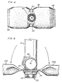
- FIG. 3 there is shown an adsorbent packet 20 in accordance with the invention.
- the elongated packet material comprises end seams 46, 48, sealing the respective longitudinal ends of the package.
- a longitudinally extending seam 44 extends longitudinally along the length of the elongated packet and slightly laterally offset from a longitudinally extending bisector line extending through the package. This seam 44 provides a double thickness of the felt like material used to form the packet 20 and therefore can be referred to as a reinforcement area.
- a circularly cross-sectioned aperture 60 is formed in the middle of the packet and is provided with a rigid heat or ultrasonically fused zone 62 surrounding the aperture.
- Tuck or fold sections 70, 82, 84 and 74 are disposed along the first widthwise edge of the pouch with tucks or folds 72, 86, 88, 76 provided in the opposing or second widthwise edge to define the pouch.
- Folds 82, 84 formed in the intermediate portion of the packet cooperate with shoulder 50 along one of the width wise edges of the packet and folds 86, 88 cooperate with shoulder 52 along the opposite width wise edge to provide a narrowed or necked-down width dimension for the packet.
- This necked down section located at an intermediate portion along the longitudinal axis of the packet facilitates packet folding. Also, during assembly, the canister housing will readily slide or fit over this reduced width portion.
- the aperture may comprise any one of a myriad of possible cross sectional shapes such as a rectangle, triangle, parallelogram, rhombus, oval, etc.
- the key criterion is that the aperture should snap or friction fit over the filter flange.
- Figure 4 depicts the top side or surface 64 of the packet 20.
- aperture 60 is provided with rigid surrounding zone 62.
- Zone 62 provides a rigid collar which will be snap mounted to the filter support flange 24.
- the packet is formed from a fibrous, air permeable material such as a synthetic felt material. Polyester felts are presently preferred but other synthetic and natural felts can of course be employed.
- FIGs 5 and 6 there is shown bight tube 16 with filter housing 22 depending therefrom.
- the filter is clasped to the bight tube by means of the mounting ring 90 and associated clasp.
- the aperture 60 is firmly, frictionally received over the support flange 24 of the filter.
- the opposed lateral sides 201, 202 of the unitary packet will be moved upwardly, against the direction of the arrows (shown in Fig. 6 ), for proper insertion into the accumulator housing.
- the pair of shoulders 50, 52 along with the rigid collar 62 surrounding the aperture, comprise a centrally located intermediate zone that extends transversely across the length of the packet.
- This zone provides a rigid, generally flat mounting area for congruent mounting of the bight tube portion therein. This helps provide stability for the adsorbent package during strenuous use conditions commonly encountered.
- the longitudinal seam 44 is parallel and adjacent to the mounting ring 90 of the filter assembly. Due to the rigid nature of the longitudinal seam, this helps to provide increased abrasion resistance of the felt packet in a location in which the ring may tend to shear or rub the packet.
- an opening is provided in the unitary package that is snap fit over the filter housing.
- the opening is surrounded by an annularly shaped rigid zone so as to help maintain stability of the packet over the filter flange.
- the diameter of the package aperture 60 is formed so that it is about .8 - .9 of the diameter of the flange.
- One successfully employed package has provided an aperture 60 diameter of about .85 - .86 of the flange outside diameter dimension.
- a tubular felted material as previously described is first provided.
- the bottom of the pouch like material is then sealed via heat seal, or other electronically sealing system, with ultrasound sealing being preferred.
- one half of the desired desiccant is filled into the pouch.
- Appropriate tucks are made in the pouch by holding the desired pouch portions in place by elongated fingers or the like and ultrasonic sealing of the area.
- the shoulder members and solid rigid zone 62 are then formed via ultrasonic sealing with the second half of the pouch then being filled with desiccant.
- the top longitudinal edge of the pouch is then sealed so as to provide a sealed packet.
- the bottom half of the next succeeding bag in the production run is sealed and the procedure repeated so that successive bags can be made.
- the central aperture 60 is cut in the middle of the zone 62.
- FIG 7A shows another version of the invention wherein a smaller packet 220 is shown for those cases in which only about 40-50 grams of desiccant is needed.
- the top half 322 of the accumulator housing is shown. This half will be welded or otherwise sealed to a bottom assembly to form the general accumulator housing structure shown in Figure 1 .
- fluid tubes 210, 212 are connected via a transversely oriented bight section with an aspirator filter housing secured to the bight tube via a ring shaped clasp (not shown).
- the packet 220 comprises end seams 246, 248 and an aperture 260 provided along one of the longitudinal packet end regions.
- the aperture 260 is surrounded by a rigid collar 262 to facilitate snap mount of the packet over the filter flange 224.
- a longitudinally extending seam 244 provides a reinforced area that is adapted for positioning adjacent the mounting clasp used to affix the filter to the fluid flow tube.
- Figure 7B depicts an alternative disposition of the packet 220 shown in Figure 7A relative to the upstanding fluid flow tubes 210, 212.
- end seam 248 of the packet has been inserted through the tubes 210, 212 so that, as shown, it is positioned in front of the plane defined by the tubes. In this manner, the end 248 is snugly affixed through the tubes 210,212 maintaining it in a fixed posture to facilitate assembly of the accumulator housing.
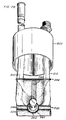
- FIG. 8 Another embodiment of the adsorbent packet is shown in Figure 8 wherein a packet 20 with elongated end seam 48 is depicted.
- the end seam has a length (extending transversely to the longitudinal dimension of the packet) that is greater than the space between the upstanding fluid flow tubes of the accumulator.
- the packet is snap fit over the filter.
- the end seam 48 is force fit or twisted for insertion between the upstanding legs 10, 12 of the accumulator tubes and placed on the far side of the tubes with respect to Figure 9 .
- end seam 48 is inserted from the front of, and then through the plane defined by the upstanding tubes 10, 12.
- the packet 20 extends in front of the plane from the snap fit mount 60 upwardly until the end seam 48 spans and grasps the tubes 10, 12 on the rearward side of the plane.
- the end seam 48 spans and abuts against the upstanding fluid flow tubes, securely working it in place so that it cannot slip between the tubes.
- the end seam 48 in this embodiment, is composed of the same fibrous material as the packet and is formed as a fusion of the top and bottom surfaces of the fibrous material.
- the end seam here may be made via ultrasonic welding or other heat sealing techniques provided that an elongated rigid member is formed.
- Feeding of the end seam 48 of the packet 20 through the tubes in the accumulator also helps to keep the packet away from the side of the can to provide improved flow and circulation of fluids, oils and gas all the way down to the filter.
- this disposition of the packet 20 also keeps the packet in concert with the tubes to position it out of the way so that the lid can go on easily in any position, horizontally, side, turned up or down.
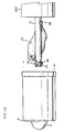
- FIG 10 there is shown another embodiment of the invention wherein the end seam 48 is provided with a rigid plastic dowel or the like, with the length of the dowel being greater than the width between the upstanding fluid flow tubes in the accumulator. Again, this provides for locking of the dowel (and the packet) through the upstanding fluid flow tubes and along the rearward plane defined by tubes 10, 12 similar to the disposition of the packet as depicted in Figures 9 and 9a .
- the end seam 48 is made with a lumen therein extending transversely to the length of the packet, rigid plastic dowel 276 so inserted through the lumen 286.
- the dowel may be fixed by being heat set into place by fusion thereof into the end seam material.
- the respective ends 278, 280 of the dowel extend beyond the width of the upstanding fluid flow tubes ( Fig. 10 ).
- dowel has been shown as being inserted through the lumen shown in Figure 11 , the skilled artisan will appreciate that the dowel could be juxtaposed with the end seam and heat or ultrasonically welded thereto.
- Figure 12 depicts another advantage of the packet structures shown in Figures 7B and 8-10 .
- the accumulator can bottom 6 is slid over the tubes 10, 12 to mate with top half 322 of the accumulator housing.
- the bottom 6 and member 322 are fixedly joined via welding, brazing or soldering or the like.
- Disposition of the packet as shown in this figure, with the end seam 48 extending through the tubes and the end seam 48 spanning the dimension between the tubes locks the packet in place, facilitating assembly of the canister and helping to space the packet from the sidewalls of the canister. This aids in inhibiting "burn-thru" that sometimes may occur if the packet is in contact with the sidewalls of the canister during the welding or joining of the can parts together.
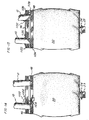
- FIG. 14 A variation on the bags of the type shown in Figure 3 is shown in Figures 14 and 15 .
- tie means 1100 such as dog bone ties extending between holes 1102, 1104 formed in the respective end seams 46, 48.
- the dog bone tie bears against the inside of one of the accumulator fluid flow tubes to help ensure lateral stability of the packet 20 in its position as attached to the tubes.
- another dog bone tie or equivalent arrangement could be made along the inside of the other fluid flow tube shown in this figure.
- FIG. 15 another embodiment is shown wherein the end seams 46, 48 are interconnected.
- the ends of the seams are provided with apertures 1122, 1124, 1126, 1128.
- Wire ties 1130, 1132 are inserted through matching pairs of these apertures with loops secured around the fluid tubes.
Landscapes
- Engineering & Computer Science (AREA)
- Chemical & Material Sciences (AREA)
- Analytical Chemistry (AREA)
- General Chemical & Material Sciences (AREA)
- Chemical Kinetics & Catalysis (AREA)
- Mechanical Engineering (AREA)
- Oil, Petroleum & Natural Gas (AREA)
- General Engineering & Computer Science (AREA)
- Power Engineering (AREA)
- Combustion & Propulsion (AREA)
- Thermal Sciences (AREA)
- Physics & Mathematics (AREA)
- External Artificial Organs (AREA)
- Treatment Of Liquids With Adsorbents In General (AREA)
Abstract
Claims (29)
- Accumulateur de liquide (2) comportant un boîtier (4), une paire de tubes d'écoulement de fluide verticaux espacés (10,12 ; 210, 212) disposés en son intérieur et reliés entre eux par une portion d'anse (16), un filtre (22) relié à ladite portion d'anse, ledit filtre comprenant une matière filtrante (23) et une bride de montage (24, 224) intercalée entre ladite portion d'anse et ladite matière filtrante, et un conditionnement adsorbant (20, 220) disposé dans le boîtier et présentant une ouverture (60, 260) dans celui-ci qui est encliquetable ou à ajustement serré sur la bride de montage (24, 224), de façon à monter le conditionnement adsorbant sur la portion d'anse (16) et à espacer le conditionnement de la matière filtrante (23),
caractérisé en ce que
le conditionnement (20, 220) a une couture disposée longitudinalement (44, 244) fournissant une double épaisseur de matériau définissant ainsi une zone renforcée s'étendant longitudinalement, le filtre (22) a une pince de montage annulaire (90) maintenant le filtre sur ladite portion d'anse (16), et ladite zone renforcée (44, 244) est positionnée contre la pince de montage (90). - Accumulateur de liquide selon la revendication 1, dans lequel la bride de montage (24, 224) a une forme généralement circulaire et une dimension de diamètre externe, et l'ouverture (60, 260) dans le conditionnement (20, 220) a une dimension de diamètre qui est d'environ 0,8 à environ 0,9 basée sur ladite dimension de diamètre de la bride de montage.
- Accumulateur de liquide selon la revendication 2, dans lequel l'ouverture (60, 260) dans le conditionnement (20, 220) a un diamètre d'environ 0,85 à 0,86 basé sur ladite dimension de diamètre externe de la bride de montage (24, 224).
- Accumulateur de liquide selon la revendication 1, 2 ou 3, dans lequel le conditionnement (20, 220) comprend une surface supérieure et une surface inférieure (42) et l'ouverture (60, 260) est entourée d'une zone de montage (62, 262) dans laquelle la surface supérieure du conditionnement est scellée sur la surface inférieure.
- Accumulateur de liquide selon l'une quelconque des revendications précédentes, dans lequel l'ouverture (260) est disposée au niveau d'une région d'extrémité longitudinale du conditionnement (220).
- Accumulateur de liquide selon l'une quelconque des revendications précédentes, dans lequel le conditionnement (20, 220) a une couture d'extrémité (48, 248) disposée transversalement par rapport à un axe longitudinal du conditionnement, ladite couture d'extrémité présentant une longueur s'étendant transversalement audit axe longitudinal, et dans lequel ladite longueur de la couture d'extrémité (48, 248) est supérieure à la distance séparant les tubes d'écoulement de fluide verticaux (10, 12 ; 210, 212), ladite couture pouvant être insérée entre les tubes d'écoulement verticaux et étant aboutée d'une manière sécurisée contre lesdits tubes d'écoulement de fluide verticaux.
- Accumulateur de liquide selon la revendication 6, dans lequel ladite couture d'extrémité (48, 248) est réalisée à partir d'un matériau raide.
- Accumulateur de liquide selon la revendication 7, dans lequel ledit matériau raide est une portion fusionnée du conditionnement (20, 220).
- Accumulateur de liquide selon la revendication 7 ou 8, dans lequel ladite couture d'extrémité (48) comporte un goujon (276).
- Accumulateur de liquide selon la revendication 9, dans lequel ladite couture d'extrémité (48) comporte une lumière (286) formée à l'intérieur de celle-ci et s'étend transversalement par rapport audit axe longitudinal, et ledit goujon (276) est inséré dans ladite lumière.
- Accumulateur de liquide selon l'une quelconque des revendications précédentes 1 à 4, dans lequel le conditionnement (20) comprend une zone intermédiaire (50, 52) orientée transversalement par rapport à un axe longitudinal du conditionnement et présentant une dimension rétrécie dans le sens de la largeur du conditionnement (20), ladite ouverture (60) étant située dans ladite zone intermédiaire.
- Accumulateur de liquide selon la revendication 11, dans lequel le conditionnement (20) est allongé et présente une première et une deuxième coutures d'extrémité (46, 48) formées aux extrémités opposées du conditionnement dans le sens de la longueur, et dans lequel lesdites coutures d'extrémité (46, 48) sont positionnées le long des côtés opposés des tubes d'écoulement de fluide verticaux (10,12) et ont des moyens de fixation (1100, 1102, 1104, 1122, 1124, 1126, 1128, 1130, 1132) pour fixer ensemble lesdites extrémités.
- Accumulateur de liquide selon la revendication 12, dans lequel lesdits moyens de fixation comportent des ouvertures (1102, 1104) formées dans les coutures d'extrémité (46, 48) et des moyens d'attache (1100, 1130, 1132) disposés à travers lesdites ouvertures.
- Accumulateur de liquide selon la revendication 13, dans lequel les moyens d'attache comportent un fil (1130, 1132).
- Accumulateur de liquide selon la revendication 13, dans lequel les moyens d'attache comportent un lien (1100).
- Conditionnement adsorbant (20, 220) destiné à être utilisé dans un accumulateur de liquide comportant une paire de tubes d'écoulement de fluide verticaux espacés (10, 12 ; 210, 212) disposés dans un boîtier (4) et reliés entre eux par une portion d'anse (16), portion d'anse qui est équipée d'un filtre (22) comprenant une matière filtrante (23) et une bride de montage (24, 224) intercalée entre la portion d'anse et la matière filtrante, conditionnement adsorbant (20, 220) qui comporte une poche allongée (20) présentant une surface supérieure et une surface inférieure (42), une paire de coutures d'extrémité (46, 48 ; 246, 248) scellant les extrémités opposées de ladite poche dans le sens de la longueur, et une ouverture (60, 260) qui est adaptée pour être encliquetée ou ajustée très serrée sur la bride de montage (24, 224), de façon à installer le conditionnement sur la portion d'anse (16) avec le conditionnement espacé par rapport à la matière filtrante (23), caractérisé en ce que
le conditionnement adsorbant présente une couture s'étendant longitudinalement (44, 244) fournissant une double épaisseur de matériau définissant ainsi une zone renforcée dans ladite surface supérieure ou inférieure. - Conditionnement adsorbant selon la revendication 16 comportant une poche (20) présentant une surface supérieure et une surface inférieure (42), ladite ouverture (60, 260) étant entourée d'une zone de montage dans laquelle la surface supérieure de la poche est scellée sur sa surface inférieure.
- Conditionnement adsorbant selon la revendication 16 ou 17 comprenant une zone intermédiaire (50, 52) de ladite poche (20) orientée transversalement par rapport à l'axe longitudinal et présentant une dimension rétrécie dans le sens de la largeur du conditionnement, ladite ouverture (60) étant située dans ladite zone intermédiaire.
- Conditionnement adsorbant selon la revendication 18, dans lequel ladite zone intermédiaire comporte une paire d'organes d'épaulement (50, 52) s'étendant dans une direction transversale par rapport à la couture disposée longitudinalement (44), ladite ouverture (60) étant située entre ladite paire d'organes d'épaulement.
- Conditionnement adsorbant selon la revendication 19, dans lequel chacun desdits organes d'épaulement (50, 52) comporte une section fusionnée fusionnant ensemble ladite surface supérieure (46) et ladite surface inférieure (42) dudit conditionnement.
- Conditionnement adsorbant selon l'une quelconque des revendications précédentes 16 à 20, dans lequel ladite ouverture (260) est située au centre sur ledit conditionnement.
- Conditionnement adsorbant selon l'une quelconque des revendications précédentes 16 à 20, dans lequel l'ouverture (60, 260) est disposée au niveau d'une région d'extrémité du conditionnement (20, 220) et ledit conditionnement est adapté pour s'étendre vers le haut le long d'un côté des tubes d'écoulement de fluide verticaux (10,12 ; 210, 212) et une couture d'extrémité opposée du conditionnement comprend un moyen de saisie (48, 248, 276) pour sécuriser ledit conditionnement contre lesdits tubes d'écoulement de fluide verticaux à un emplacement sur les côtés opposés.
- Conditionnement adsorbant selon la revendication 22, dans lequel ledit moyen de saisie comprend une couture d'extrémité allongée dont les dimensions sont supérieures en largeur à la distance séparant lesdits tubes d'écoulement de fluide verticaux (10, 12, 210, 212).
- Conditionnement adsorbant selon la revendication 22, dans lequel ledit moyen de saisie comporte un goujon (276) sécurisé au niveau de ladite couture d'extrémité, ledit goujon (276) étant dimensionné de façon à ce que sa longueur soit supérieure à la distance séparant lesdits tubes d'écoulement de fluide verticaux (10,12).
- Conditionnement adsorbant selon la revendication 24 comprenant une lumière (286) formée au niveau de ladite couture d'extrémité du conditionnement (20), ledit goujon (276) étant inséré dans ladite lumière (286).
- Conditionnement adsorbant selon l'une quelconque des revendication précédentes 16 à 21, dans lequel la poche présente une première et une deuxième coutures d'extrémité (46, 48) avec l'ouverture (60) située entre les deux, et dans lequel le conditionnement est adapté pour être plié vers le haut le long des tubes d'écoulement de fluide (10,12) avec ses première et deuxième coutures d'extrémité opposées l'une à l'autre, et le conditionnement comprend des moyens de sécurisation (1100, 1102, 1104, 1122, 1124, 1116, 1128, 1130, 1132) pour sécuriser lesdites première et deuxième coutures d'extrémité ensemble.
- Conditionnement adsorbant selon la revendication 26 dans lequel lesdites première et deuxième coutures d'extrémité (46, 48) comportent chacune une portion fusionnée rigide de ladite poche (20).
- Conditionnement adsorbant selon la revendication 26 ou 27, dans lequel ledit moyen de sécurisation comporte des ouvertures (1102, 1104, 1122, 1124, 1126, 1128) formées dans lesdites première et deuxième coutures d'extrémité (46, 48) et des fils (1130,1132) traversant lesdites ouvertures.
- Conditionnement adsorbant selon la revendication 26 ou 27, dans lequel ledit moyen de sécurisation comporte des ouvertures (1102) formées dans lesdites première et deuxième coutures d'extrémité et un lien en forme de bobine (1100) traversant lesdites ouvertures (1102).
Applications Claiming Priority (9)
| Application Number | Priority Date | Filing Date | Title |
|---|---|---|---|
| US6963097P | 1997-12-15 | 1997-12-15 | |
| US69630P | 1997-12-15 | ||
| US09/013,397 US6083303A (en) | 1996-04-17 | 1998-01-26 | Snap on desiccant bag |
| US13397 | 1998-01-26 | ||
| US7382598P | 1998-02-05 | 1998-02-05 | |
| US73825P | 1998-02-05 | ||
| US09/060,119 US6083305A (en) | 1997-12-15 | 1998-04-14 | Snap on desiccant bag |
| US60119 | 1998-04-14 | ||
| PCT/US1998/025350 WO1999030805A1 (fr) | 1997-12-15 | 1998-11-30 | Sac de deshydratant s'ajustant par declic |
Publications (3)
| Publication Number | Publication Date |
|---|---|
| EP1062020A1 EP1062020A1 (fr) | 2000-12-27 |
| EP1062020A4 EP1062020A4 (fr) | 2002-05-29 |
| EP1062020B1 true EP1062020B1 (fr) | 2008-05-14 |
Family
ID=27486293
Family Applications (1)
| Application Number | Title | Priority Date | Filing Date |
|---|---|---|---|
| EP98960544A Expired - Lifetime EP1062020B1 (fr) | 1997-12-15 | 1998-11-30 | Sac de deshydratant s'ajustant par declic |
Country Status (5)
| Country | Link |
|---|---|
| US (1) | US6083305A (fr) |
| EP (1) | EP1062020B1 (fr) |
| CA (1) | CA2310654C (fr) |
| DE (1) | DE69839496D1 (fr) |
| WO (1) | WO1999030805A1 (fr) |
Families Citing this family (7)
| Publication number | Priority date | Publication date | Assignee | Title |
|---|---|---|---|---|
| US6178773B1 (en) | 1999-12-03 | 2001-01-30 | Multisorb Technologies, Inc. | Self-retaining adsorbent unit |
| US6395074B1 (en) | 2000-05-16 | 2002-05-28 | Stanhope Products Company | Desiccant bag with integrated filter and method of making same |
| US6494057B1 (en) * | 2000-07-20 | 2002-12-17 | Carrier Corporation | Combination accumulator filter drier |
| DE10037277C1 (de) * | 2000-07-28 | 2001-09-13 | Hansa Metallwerke Ag | Akkumulator für eine nach dem Orifice-Prinzip arbeitende Klimaanlage, insbesondere Fahrzeugklimaanlage |
| US6481241B1 (en) * | 2001-08-29 | 2002-11-19 | Automotive Fluid Systems, Inc. | Accumulator desiccant bag and method of assembling |
| US10168085B2 (en) * | 2011-03-09 | 2019-01-01 | Mahle International Gmbh | Condenser having a refrigerant reservoir assembly containing a desiccant bag |
| CN117836573A (zh) * | 2021-08-24 | 2024-04-05 | 株式会社不二工机 | 储液器 |
Family Cites Families (24)
| Publication number | Priority date | Publication date | Assignee | Title |
|---|---|---|---|---|
| US3879292A (en) * | 1972-03-20 | 1975-04-22 | Clecon Inc | Desiccant device |
| US4116649A (en) * | 1976-01-16 | 1978-09-26 | Multiform Desiccant Products, Inc. | Self-retaining adsorbent bag unit |
| US4401447A (en) * | 1979-08-31 | 1983-08-30 | Multiform Desiccants, Inc. | Self-retaining adsorbent bag unit |
| US4291548A (en) * | 1980-07-07 | 1981-09-29 | General Motors Corporation | Liquid accumulator |
| US4405347A (en) * | 1982-01-11 | 1983-09-20 | Multiform Desiccants, Inc. | Adsorbent unit for mounting in the upper portion of a refrigerant receiver |
| US4457843A (en) * | 1982-05-12 | 1984-07-03 | Multiform Desiccants, Inc. | Self-retaining adsorbent container |
| US4436623A (en) * | 1982-07-28 | 1984-03-13 | Multiform Desiccants, Inc. | Adsorbent cartridge |
| US4464261A (en) * | 1982-07-28 | 1984-08-07 | Multiform Desiccants, Inc. | Adsorbent device |
| US4496378A (en) * | 1982-12-16 | 1985-01-29 | Murray Corporation | Accumulator dehydrator |
| US4474035A (en) * | 1983-12-23 | 1984-10-02 | Ford Motor Company | Domed accumulator for automotive air conditioning system |
| US4619673A (en) * | 1985-05-15 | 1986-10-28 | Multiform Desiccants, Inc. | Adsorbent device |
| US4994185A (en) * | 1989-03-23 | 1991-02-19 | Multiform Desiccants, Inc. | Combined heat shielding and bonding device for adsorbent packet in refrigerant receiver |
| US4921512A (en) * | 1989-03-30 | 1990-05-01 | American Optical Corporation | Filter element |
| US4911739A (en) * | 1989-07-07 | 1990-03-27 | Multiform Desiccants, Inc. | Self-retaining adsorbent cartridge for refrigerant receiver |
| US5036972A (en) * | 1990-04-25 | 1991-08-06 | Multiform Desiccants, Inc. | Adsorbent packet with integral heat shield and method of fabrication thereof |
| US5177982A (en) * | 1991-12-23 | 1993-01-12 | Ford Motor Company | Accumulator desiccant bag retaining clip |
| US5569316A (en) * | 1995-03-01 | 1996-10-29 | Stanhope Products Company | Desiccant container having mount for canister tube and inner wall extension portion |
| US5580451A (en) * | 1995-05-01 | 1996-12-03 | Automotive Fluid Systems, Inc. | Air conditioning refrigerant fluid dryer assembly |
| US5693124A (en) * | 1995-09-13 | 1997-12-02 | Multisorb Technologies, Inc. | Accumulator desiccant bag |
| US5718743A (en) * | 1996-02-26 | 1998-02-17 | Multisorb Technologies, Inc. | Desiccant cartridge |
| US5636525A (en) * | 1996-04-02 | 1997-06-10 | Multisorb Technologies, Inc. | Saddle type adsorbent unit |
| US5837039A (en) * | 1996-04-17 | 1998-11-17 | Stanhope Products Company | Adsorbent packet for air conditioning accumulators |
| US5865998A (en) * | 1996-07-09 | 1999-02-02 | Calsonic North America, Inc. | Receiver-dryer assembly and desiccant bag therefor |
| US5814136A (en) * | 1997-04-15 | 1998-09-29 | Stanhope Products Company | Desiccant container |
-
1998
- 1998-04-14 US US09/060,119 patent/US6083305A/en not_active Expired - Fee Related
- 1998-11-30 DE DE69839496T patent/DE69839496D1/de not_active Expired - Lifetime
- 1998-11-30 CA CA002310654A patent/CA2310654C/fr not_active Expired - Fee Related
- 1998-11-30 WO PCT/US1998/025350 patent/WO1999030805A1/fr not_active Ceased
- 1998-11-30 EP EP98960544A patent/EP1062020B1/fr not_active Expired - Lifetime
Also Published As
| Publication number | Publication date |
|---|---|
| EP1062020A1 (fr) | 2000-12-27 |
| CA2310654A1 (fr) | 1999-06-24 |
| CA2310654C (fr) | 2005-11-15 |
| WO1999030805A1 (fr) | 1999-06-24 |
| US6083305A (en) | 2000-07-04 |
| DE69839496D1 (de) | 2008-06-26 |
| EP1062020A4 (fr) | 2002-05-29 |
Similar Documents
| Publication | Publication Date | Title |
|---|---|---|
| US5914456A (en) | Adsorbent packet for air conditioning accumulators | |
| US5636525A (en) | Saddle type adsorbent unit | |
| US4401447A (en) | Self-retaining adsorbent bag unit | |
| EP1062020B1 (fr) | Sac de deshydratant s'ajustant par declic | |
| US6155072A (en) | Snap on desiccant bag | |
| EP1371569A1 (fr) | Sachet | |
| US6083303A (en) | Snap on desiccant bag | |
| US5693124A (en) | Accumulator desiccant bag | |
| JP3247111B2 (ja) | 流体用たわみ性容器 | |
| US6449977B1 (en) | Self-retaining elongated adsorbent unit | |
| CA2324914C (fr) | Unite adsorbante avec compartiment pour traceur frigorigene | |
| EP2016351B1 (fr) | Ensemble poche à desséchant et filtre | |
| US6481241B1 (en) | Accumulator desiccant bag and method of assembling | |
| CA2377388C (fr) | Bloc d'adsorption auto-bloquant | |
| AU2002301460B2 (en) | Accumulator and fixing structure of desiccant in the same | |
| WO1999061848A1 (fr) | Ensemble adsorbant de type sellette | |
| JP4014781B2 (ja) | アキュムレータ | |
| WO2000019156A1 (fr) | Emballage adsorbant auto-reglable pour reservoirs tampons d'appareils de conditionnement d'air | |
| US6257015B1 (en) | Self-retaining adsorbent unit | |
| WO1997019005A1 (fr) | Sachet d'infusion et sa fabrication | |
| US20030208998A1 (en) | Filter bag and method of manufacture thereof | |
| EP1295073B1 (fr) | Tube en u et unite adsorbante integres | |
| WO2001040718A1 (fr) | Unite adsorbante de retention | |
| CN212440275U (zh) | 带有防破损结构的滤袋 | |
| WO2002029338A1 (fr) | Unite adsorbante autobloquante |
Legal Events
| Date | Code | Title | Description |
|---|---|---|---|
| PUAI | Public reference made under article 153(3) epc to a published international application that has entered the european phase |
Free format text: ORIGINAL CODE: 0009012 |
|
| 17P | Request for examination filed |
Effective date: 20000623 |
|
| AK | Designated contracting states |
Kind code of ref document: A1 Designated state(s): DE FR GB IT |
|
| RIN1 | Information on inventor provided before grant (corrected) |
Inventor name: WOOD, RAYMOND, B. Inventor name: LECONEY, DOUGLAS, E. |
|
| A4 | Supplementary search report drawn up and despatched |
Effective date: 20020412 |
|
| AK | Designated contracting states |
Kind code of ref document: A4 Designated state(s): DE FR GB IT |
|
| RIC1 | Information provided on ipc code assigned before grant |
Free format text: 7B 01D 53/04 A, 7B 01D 53/26 B, 7F 25B 43/00 B |
|
| 17Q | First examination report despatched |
Effective date: 20040514 |
|
| RAP1 | Party data changed (applicant data changed or rights of an application transferred) |
Owner name: FLOW DRY TECHNOLOGY LTD |
|
| 17Q | First examination report despatched |
Effective date: 20040514 |
|
| RAP1 | Party data changed (applicant data changed or rights of an application transferred) |
Owner name: FLOW DRY TECHNOLOGY, INC |
|
| GRAC | Information related to communication of intention to grant a patent modified |
Free format text: ORIGINAL CODE: EPIDOSCIGR1 |
|
| GRAP | Despatch of communication of intention to grant a patent |
Free format text: ORIGINAL CODE: EPIDOSNIGR1 |
|
| GRAS | Grant fee paid |
Free format text: ORIGINAL CODE: EPIDOSNIGR3 |
|
| GRAA | (expected) grant |
Free format text: ORIGINAL CODE: 0009210 |
|
| AK | Designated contracting states |
Kind code of ref document: B1 Designated state(s): DE FR GB IT |
|
| REG | Reference to a national code |
Ref country code: GB Ref legal event code: FG4D |
|
| REF | Corresponds to: |
Ref document number: 69839496 Country of ref document: DE Date of ref document: 20080626 Kind code of ref document: P |
|
| PLBE | No opposition filed within time limit |
Free format text: ORIGINAL CODE: 0009261 |
|
| STAA | Information on the status of an ep patent application or granted ep patent |
Free format text: STATUS: NO OPPOSITION FILED WITHIN TIME LIMIT |
|
| 26N | No opposition filed |
Effective date: 20090217 |
|
| GBPC | Gb: european patent ceased through non-payment of renewal fee |
Effective date: 20081130 |
|
| PG25 | Lapsed in a contracting state [announced via postgrant information from national office to epo] |
Ref country code: IT Free format text: LAPSE BECAUSE OF FAILURE TO SUBMIT A TRANSLATION OF THE DESCRIPTION OR TO PAY THE FEE WITHIN THE PRESCRIBED TIME-LIMIT Effective date: 20080514 |
|
| REG | Reference to a national code |
Ref country code: FR Ref legal event code: ST Effective date: 20090731 |
|
| PG25 | Lapsed in a contracting state [announced via postgrant information from national office to epo] |
Ref country code: GB Free format text: LAPSE BECAUSE OF NON-PAYMENT OF DUE FEES Effective date: 20081130 |
|
| PG25 | Lapsed in a contracting state [announced via postgrant information from national office to epo] |
Ref country code: FR Free format text: LAPSE BECAUSE OF NON-PAYMENT OF DUE FEES Effective date: 20081130 |
|
| PGFP | Annual fee paid to national office [announced via postgrant information from national office to epo] |
Ref country code: DE Payment date: 20141128 Year of fee payment: 17 |
|
| REG | Reference to a national code |
Ref country code: DE Ref legal event code: R119 Ref document number: 69839496 Country of ref document: DE |
|
| PG25 | Lapsed in a contracting state [announced via postgrant information from national office to epo] |
Ref country code: DE Free format text: LAPSE BECAUSE OF NON-PAYMENT OF DUE FEES Effective date: 20160601 |