EP1062030B1 - Verfahren und vorrichtung zur steuerung des wärmeübergangs von feststoffpartikeln in ein wirbelbett - Google Patents
Verfahren und vorrichtung zur steuerung des wärmeübergangs von feststoffpartikeln in ein wirbelbett Download PDFInfo
- Publication number
- EP1062030B1 EP1062030B1 EP97948918A EP97948918A EP1062030B1 EP 1062030 B1 EP1062030 B1 EP 1062030B1 EP 97948918 A EP97948918 A EP 97948918A EP 97948918 A EP97948918 A EP 97948918A EP 1062030 B1 EP1062030 B1 EP 1062030B1
- Authority
- EP
- European Patent Office
- Prior art keywords
- heat transfer
- chamber
- transfer chamber
- velocity
- flow
- Prior art date
- Legal status (The legal status is an assumption and is not a legal conclusion. Google has not performed a legal analysis and makes no representation as to the accuracy of the status listed.)
- Expired - Lifetime
Links
- 238000012546 transfer Methods 0.000 title claims abstract description 232
- 239000002245 particle Substances 0.000 title claims abstract description 88
- 239000007787 solid Substances 0.000 title claims abstract description 73
- 238000000034 method Methods 0.000 title claims abstract description 42
- 238000005243 fluidization Methods 0.000 claims abstract description 18
- 238000012545 processing Methods 0.000 claims description 34
- 238000002485 combustion reaction Methods 0.000 claims description 20
- 239000000463 material Substances 0.000 claims description 18
- 238000012544 monitoring process Methods 0.000 claims description 12
- 230000008859 change Effects 0.000 claims description 10
- 230000000737 periodic effect Effects 0.000 claims description 8
- 238000004891 communication Methods 0.000 claims description 6
- 238000007599 discharging Methods 0.000 claims description 5
- 239000011343 solid material Substances 0.000 claims description 4
- XLYOFNOQVPJJNP-UHFFFAOYSA-N water Substances O XLYOFNOQVPJJNP-UHFFFAOYSA-N 0.000 claims description 3
- 239000007789 gas Substances 0.000 description 69
- 230000001276 controlling effect Effects 0.000 description 13
- 230000005587 bubbling Effects 0.000 description 12
- 239000012530 fluid Substances 0.000 description 8
- 230000008569 process Effects 0.000 description 7
- 238000011084 recovery Methods 0.000 description 6
- 238000010276 construction Methods 0.000 description 5
- 239000000446 fuel Substances 0.000 description 4
- 230000007704 transition Effects 0.000 description 4
- 230000032258 transport Effects 0.000 description 4
- 238000002347 injection Methods 0.000 description 3
- 239000007924 injection Substances 0.000 description 3
- 238000004064 recycling Methods 0.000 description 3
- 230000005856 abnormality Effects 0.000 description 2
- 238000005054 agglomeration Methods 0.000 description 2
- 230000002776 aggregation Effects 0.000 description 2
- 238000001816 cooling Methods 0.000 description 2
- 238000009826 distribution Methods 0.000 description 2
- 230000000694 effects Effects 0.000 description 2
- 238000005259 measurement Methods 0.000 description 2
- 238000002156 mixing Methods 0.000 description 2
- 238000013021 overheating Methods 0.000 description 2
- 239000012254 powdered material Substances 0.000 description 2
- 230000036962 time dependent Effects 0.000 description 2
- 238000013459 approach Methods 0.000 description 1
- 238000009529 body temperature measurement Methods 0.000 description 1
- 238000001311 chemical methods and process Methods 0.000 description 1
- 238000006243 chemical reaction Methods 0.000 description 1
- 230000007797 corrosion Effects 0.000 description 1
- 238000005260 corrosion Methods 0.000 description 1
- 230000007423 decrease Effects 0.000 description 1
- 230000003247 decreasing effect Effects 0.000 description 1
- 230000001627 detrimental effect Effects 0.000 description 1
- 238000005516 engineering process Methods 0.000 description 1
- 230000002349 favourable effect Effects 0.000 description 1
- 239000008187 granular material Substances 0.000 description 1
- 239000013529 heat transfer fluid Substances 0.000 description 1
- 239000002184 metal Substances 0.000 description 1
- 238000010310 metallurgical process Methods 0.000 description 1
- 238000005192 partition Methods 0.000 description 1
- 230000010349 pulsation Effects 0.000 description 1
- 230000003134 recirculating effect Effects 0.000 description 1
- 230000004044 response Effects 0.000 description 1
- 238000003860 storage Methods 0.000 description 1
- 239000000126 substance Substances 0.000 description 1
- 238000012360 testing method Methods 0.000 description 1
Images


Classifications
-
- F—MECHANICAL ENGINEERING; LIGHTING; HEATING; WEAPONS; BLASTING
- F28—HEAT EXCHANGE IN GENERAL
- F28D—HEAT-EXCHANGE APPARATUS, NOT PROVIDED FOR IN ANOTHER SUBCLASS, IN WHICH THE HEAT-EXCHANGE MEDIA DO NOT COME INTO DIRECT CONTACT
- F28D13/00—Heat-exchange apparatus using a fluidised bed
-
- B—PERFORMING OPERATIONS; TRANSPORTING
- B01—PHYSICAL OR CHEMICAL PROCESSES OR APPARATUS IN GENERAL
- B01J—CHEMICAL OR PHYSICAL PROCESSES, e.g. CATALYSIS OR COLLOID CHEMISTRY; THEIR RELEVANT APPARATUS
- B01J8/00—Chemical or physical processes in general, conducted in the presence of fluids and solid particles; Apparatus for such processes
- B01J8/18—Chemical or physical processes in general, conducted in the presence of fluids and solid particles; Apparatus for such processes with fluidised particles
- B01J8/1818—Feeding of the fluidising gas
- B01J8/1827—Feeding of the fluidising gas the fluidising gas being a reactant
-
- B—PERFORMING OPERATIONS; TRANSPORTING
- B01—PHYSICAL OR CHEMICAL PROCESSES OR APPARATUS IN GENERAL
- B01J—CHEMICAL OR PHYSICAL PROCESSES, e.g. CATALYSIS OR COLLOID CHEMISTRY; THEIR RELEVANT APPARATUS
- B01J8/00—Chemical or physical processes in general, conducted in the presence of fluids and solid particles; Apparatus for such processes
- B01J8/18—Chemical or physical processes in general, conducted in the presence of fluids and solid particles; Apparatus for such processes with fluidised particles
- B01J8/1836—Heating and cooling the reactor
-
- B—PERFORMING OPERATIONS; TRANSPORTING
- B01—PHYSICAL OR CHEMICAL PROCESSES OR APPARATUS IN GENERAL
- B01J—CHEMICAL OR PHYSICAL PROCESSES, e.g. CATALYSIS OR COLLOID CHEMISTRY; THEIR RELEVANT APPARATUS
- B01J8/00—Chemical or physical processes in general, conducted in the presence of fluids and solid particles; Apparatus for such processes
- B01J8/18—Chemical or physical processes in general, conducted in the presence of fluids and solid particles; Apparatus for such processes with fluidised particles
- B01J8/24—Chemical or physical processes in general, conducted in the presence of fluids and solid particles; Apparatus for such processes with fluidised particles according to "fluidised-bed" technique
- B01J8/26—Chemical or physical processes in general, conducted in the presence of fluids and solid particles; Apparatus for such processes with fluidised particles according to "fluidised-bed" technique with two or more fluidised beds, e.g. reactor and regeneration installations
-
- B—PERFORMING OPERATIONS; TRANSPORTING
- B01—PHYSICAL OR CHEMICAL PROCESSES OR APPARATUS IN GENERAL
- B01J—CHEMICAL OR PHYSICAL PROCESSES, e.g. CATALYSIS OR COLLOID CHEMISTRY; THEIR RELEVANT APPARATUS
- B01J8/00—Chemical or physical processes in general, conducted in the presence of fluids and solid particles; Apparatus for such processes
- B01J8/18—Chemical or physical processes in general, conducted in the presence of fluids and solid particles; Apparatus for such processes with fluidised particles
- B01J8/24—Chemical or physical processes in general, conducted in the presence of fluids and solid particles; Apparatus for such processes with fluidised particles according to "fluidised-bed" technique
- B01J8/38—Chemical or physical processes in general, conducted in the presence of fluids and solid particles; Apparatus for such processes with fluidised particles according to "fluidised-bed" technique with fluidised bed containing a rotatable device or being subject to rotation or to a circulatory movement, i.e. leaving a vessel and subsequently re-entering it
- B01J8/384—Chemical or physical processes in general, conducted in the presence of fluids and solid particles; Apparatus for such processes with fluidised particles according to "fluidised-bed" technique with fluidised bed containing a rotatable device or being subject to rotation or to a circulatory movement, i.e. leaving a vessel and subsequently re-entering it being subject to a circulatory movement only
- B01J8/388—Chemical or physical processes in general, conducted in the presence of fluids and solid particles; Apparatus for such processes with fluidised particles according to "fluidised-bed" technique with fluidised bed containing a rotatable device or being subject to rotation or to a circulatory movement, i.e. leaving a vessel and subsequently re-entering it being subject to a circulatory movement only externally, i.e. the particles leaving the vessel and subsequently re-entering it
-
- B—PERFORMING OPERATIONS; TRANSPORTING
- B01—PHYSICAL OR CHEMICAL PROCESSES OR APPARATUS IN GENERAL
- B01J—CHEMICAL OR PHYSICAL PROCESSES, e.g. CATALYSIS OR COLLOID CHEMISTRY; THEIR RELEVANT APPARATUS
- B01J8/00—Chemical or physical processes in general, conducted in the presence of fluids and solid particles; Apparatus for such processes
- B01J8/18—Chemical or physical processes in general, conducted in the presence of fluids and solid particles; Apparatus for such processes with fluidised particles
- B01J8/24—Chemical or physical processes in general, conducted in the presence of fluids and solid particles; Apparatus for such processes with fluidised particles according to "fluidised-bed" technique
- B01J8/40—Chemical or physical processes in general, conducted in the presence of fluids and solid particles; Apparatus for such processes with fluidised particles according to "fluidised-bed" technique with fluidised bed subjected to vibrations or pulsations
-
- F—MECHANICAL ENGINEERING; LIGHTING; HEATING; WEAPONS; BLASTING
- F22—STEAM GENERATION
- F22B—METHODS OF STEAM GENERATION; STEAM BOILERS
- F22B31/00—Modifications of boiler construction, or of tube systems, dependent on installation of combustion apparatus; Arrangements or dispositions of combustion apparatus
- F22B31/0007—Modifications of boiler construction, or of tube systems, dependent on installation of combustion apparatus; Arrangements or dispositions of combustion apparatus with combustion in a fluidized bed
- F22B31/0084—Modifications of boiler construction, or of tube systems, dependent on installation of combustion apparatus; Arrangements or dispositions of combustion apparatus with combustion in a fluidized bed with recirculation of separated solids or with cooling of the bed particles outside the combustion bed
-
- F—MECHANICAL ENGINEERING; LIGHTING; HEATING; WEAPONS; BLASTING
- F23—COMBUSTION APPARATUS; COMBUSTION PROCESSES
- F23C—METHODS OR APPARATUS FOR COMBUSTION USING FLUID FUEL OR SOLID FUEL SUSPENDED IN A CARRIER GAS OR AIR
- F23C10/00—Fluidised bed combustion apparatus
- F23C10/18—Details; Accessories
- F23C10/28—Control devices specially adapted for fluidised bed, combustion apparatus
-
- B—PERFORMING OPERATIONS; TRANSPORTING
- B01—PHYSICAL OR CHEMICAL PROCESSES OR APPARATUS IN GENERAL
- B01J—CHEMICAL OR PHYSICAL PROCESSES, e.g. CATALYSIS OR COLLOID CHEMISTRY; THEIR RELEVANT APPARATUS
- B01J2208/00—Processes carried out in the presence of solid particles; Reactors therefor
- B01J2208/00008—Controlling the process
- B01J2208/00017—Controlling the temperature
- B01J2208/00026—Controlling or regulating the heat exchange system
- B01J2208/00035—Controlling or regulating the heat exchange system involving measured parameters
- B01J2208/00044—Temperature measurement
- B01J2208/00053—Temperature measurement of the heat exchange medium
-
- B—PERFORMING OPERATIONS; TRANSPORTING
- B01—PHYSICAL OR CHEMICAL PROCESSES OR APPARATUS IN GENERAL
- B01J—CHEMICAL OR PHYSICAL PROCESSES, e.g. CATALYSIS OR COLLOID CHEMISTRY; THEIR RELEVANT APPARATUS
- B01J2208/00—Processes carried out in the presence of solid particles; Reactors therefor
- B01J2208/00008—Controlling the process
- B01J2208/00017—Controlling the temperature
- B01J2208/00026—Controlling or regulating the heat exchange system
- B01J2208/00035—Controlling or regulating the heat exchange system involving measured parameters
- B01J2208/00088—Flow rate measurement
-
- B—PERFORMING OPERATIONS; TRANSPORTING
- B01—PHYSICAL OR CHEMICAL PROCESSES OR APPARATUS IN GENERAL
- B01J—CHEMICAL OR PHYSICAL PROCESSES, e.g. CATALYSIS OR COLLOID CHEMISTRY; THEIR RELEVANT APPARATUS
- B01J2208/00—Processes carried out in the presence of solid particles; Reactors therefor
- B01J2208/00008—Controlling the process
- B01J2208/00017—Controlling the temperature
- B01J2208/00106—Controlling the temperature by indirect heat exchange
- B01J2208/00115—Controlling the temperature by indirect heat exchange with heat exchange elements inside the bed of solid particles
- B01J2208/00132—Tubes
-
- F—MECHANICAL ENGINEERING; LIGHTING; HEATING; WEAPONS; BLASTING
- F23—COMBUSTION APPARATUS; COMBUSTION PROCESSES
- F23C—METHODS OR APPARATUS FOR COMBUSTION USING FLUID FUEL OR SOLID FUEL SUSPENDED IN A CARRIER GAS OR AIR
- F23C2206/00—Fluidised bed combustion
- F23C2206/10—Circulating fluidised bed
- F23C2206/103—Cooling recirculating particles
Definitions
- the present invention relates to a method of and an apparatus for controlling heat transfer in a fluidized bed reactor, according to the preambles of appended independent claims.
- the present invention particularly relates to a method and an apparatus for recovering heat from solid particles in a fluidized bed reactor comprising a processing chamber, having a fluidized bed of solid particles therein, and a heat transfer chamber, being in solid particle communication with the processing chamber and having heat transfer surfaces disposed therein.
- the heat transfer chamber may be connected in various ways to the processing chamber so that there is solid particle exchange between the chambers.
- the heat transfer chamber may in some special case even be formed within the processing chamber itself.
- the present invention relates to a method and apparatus applicable in atmospheric, as well as, pressurized fluidized bed reactor systems.
- Fluidized bed reactors such as circulating fluidized bed reactors, are used in a variety of different combustion, heat transfer, chemical or metallurgical processes.
- heat originating from combustion or other exothermic processes, is recovered from the solid particles of the fluidized bed by using heat transfer surfaces. Heat transfer surfaces conduct the recovered heat to a medium, such as water or steam, which transports the heat from the reactor.
- Said heat transfer surfaces are usually located in the processing chamber or within a convection section arranged in the gas pass after the processing chamber or, in circulating fluidized bed reactors, within a particle separator. Additional heat transfer surfaces may be arranged in separate heat transfer chambers (HTC), which may be a part of the processing chamber, a separate chamber adjacent to the processing chamber or, in circulating fluidized bed reactors, part of the solid particles recycling system.
- HTC heat transfer chambers
- heat is typically recovered by continuously introducing hot solid particles from e.g. the processing chamber into the HTC, recovering heat from said solid particles in the HTC, and continuously discharging said solid particles from the HTC into the processing chamber. Said heat recovery takes place by using heat transfer surfaces disposed in the HTC.
- the HTC thereby comprises inlet means for introducing a continuous flow of hot solid particles from the processing chamber into the HTC, heat transfer surfaces and means for transporting the heat recovered from the hot solid particles out from the HTC, and outlet means for continuously recycling solid particles discharged from the HTC into the processing chamber.
- the aim of the heat transfer control is to maintain optimum performance, especially taking into account the harmful emissions or combustion efficiency. Usually, this implies that the temperature of the reactor should stay constant, even in conditions of varying heat recovery and fuel input rates.
- the rate of heat recovery in the upper parts of the furnace can be varied by changing the bed density. This can be realized by collecting part of the bed material to a storage, as shown in US patent 4,823,739 or, more simply and quickly, by changing the fluidizing gas velocity.
- the fluidizing gas is an important factor in reactions taking place in the processing chamber of the circulating fluidized bed reactor.
- changes in the fluidizing gas require other simultaneous changes, such as changes in the fuel feed rate.
- this method of heat transfer control effects all heat transfer surfaces of the system and can be favorably put into effect only in the time scale of the thermal time constant of the whole system.
- the thermal time constant of a fluidized bed reactor i.e. the time when, after a step-wise stimulus, approximately two thirds of its temperature change has taken place, can be very long, e.g. 25 minutes.
- the heat transfer from a fluidized bed based an heat transfer surfaces having an invariable thermal contact to the bed is not fast enough for many applications of fluidized bed reactors.
- the simplest means for such control is to vary, the amount of hot material in contact with the heat transfer surfaces in the HTC so that only a variable part of the heat transfer surfaces is covered by the solid particles.
- This kind of construction was disclosed e.g. in US patent 4,813,479.
- to control the level of solid particles at least one additional flow duct and a controlling valve is needed, which increases the complexity and costs of the system.
- HTCs are normally bubbling fluidized beds with low gas flow velocities, e.g. from 0.1 to 0.5 m/s.
- the transport of solid particles through an HTC or through its different channels can be controlled by mechanical valves or by varying the fluidizing gas velocity, and thereby the bed height, in different portions of the HTC.
- the heat transfer coefficient refers to the amount of thermal energy transferred across one square meter of the heat transfer surface per one degree temperature difference between the bed and the medium transporting the heat away.
- US patent 5,425,412 discloses an arrangement in the return duct of a circulating fluidized bed reactor, where the HTC contains a separate heat transfer section where the gas flow velocity can be varied independently from the particle flow.
- US patent 5,406,914 discloses another arrangement with a separate heat transfer section which has also an additional passage for particles directly from the processing chamber to the HTC. With a similar principle can also be constructed a separate HTC, with a heat transfer gas flow which is independent of the particle transfer gas flow.
- a further drawback of the suggested heat transfer control based an pulsed gas flow velocity, including zero gas flow velocities, is the poor mixing of the solid particles in the HTC. Particularly if afterburning takes place, there is a risk of overheating and agglomeration of bed material at some locations of the HTC. It has also been noticed that nozzles in the bottom of a fluidized bed reactor have a tendency to leak unless a minimum gas velocity is maintained in the reactor.
- the present invention provides an improved method of and apparatus for controlling heat transfer in a fluidized bed reactor, which includes a heat transfer chamber (HTC) with a bed of solid particles therein, means for continuously, i.e. substantially uninterruptedly, introducing fluidizing gas into the heat transfer chamber for fluidizing said bed of solid particles therein and heat transfer surfaces in contact with said bed of solid particles in said heat transfer chamber, the heat transfer surfaces recovering heat from solid particles in the heat transfer chamber.
- the fluidized bed reactor according to the present invention further comprises means for varying the continuous fluidization of the bed of solid particles in the heat transfer chamber according to a periodical function.
- the flow of fluidizing gas, which is continuously introduced into the heat transfer chamber is periodically varied between two or more different flow velocities, for controlling the instantaneous heat transfer from solid particles to said heat transfer surfaces in said heat transfer chamber.
- the effective or average overall heat transfer in the heat transfer chamber is thereby controlled by varying a parameter of the periodically varying flow of fluidizing gas being introduced into the heat transfer chamber.
- the present invention is applicable in different types of fluidized bed reactors, such as in bubbling fluidized bed reactors or in circulating fluidized bed (CFB) reactors.
- the fluidized bed reactor comprises a processing chamber, such as a combustion chamber, in solid particle flow communication with the heat transfer chamber. Heat generated in said processing chamber is thereby recovered with the heat transfer surfaces in the heat transfer chamber.
- the heat transfer chamber in which heat transfer is controlled according to the present invention, may even be an integral part of a bubbling fluidized bed reactor, i.e. at least a portion of the bubbling bed itself may form a heat transfer "chamber" zone.
- the invention is also applicable in fluidized bed ash coolers, cooling ash and/or other bed material discharged from the combustion chamber of a fluidized bed reactor.
- the heat transfer chamber may be connected to a CFB as an external heat exchanger in the solid material recirculation loop or as an internal heat exchanger connected to the internal bed material circulation.
- an improved method of recovering heat from solid particles in a fluidized bed reactor, utilizing an HTC comprising the steps of:
- the method may have the steps of:
- an improved apparatus for recovering heat from solid particles in a fluidized bed reactor, utilizing an HTC comprising:
- the apparatus may have:
- the flow velocity of a continuous flow of gas is alternated between a first and a second flow velocity, said first flow velocity being higher than the second velocity, said first flow velocity thereby providing a higher instantaneous heat transfer from the solid particles to the heat transfer surfaces than the second flow velocity.
- the flow velocity may, if needed or otherwise desired, be alternated between more than two different flow velocities.
- the lowermost flow velocity should mainly be set to a level which prevents the fluidization nozzles from leaking or being blocked by particles falling into or an the nozzle openings.
- the minimum value of the periodically varying fluidization gas flow velocity in the HTC should preferably be maintained at a level corresponding to at least 10%, preferably at least 20%, of the maximum value of the periodically varying fluidization gas flow velocity in the HTC.
- the flow velocity of the gas being introduced into the heat transfer chamber may also be periodically varied according to e.g. a step-wise function, a saw-tooth function, a sine function or the like.
- the form of the function normally is not important.
- the form of the function generally depends an the construction of the means providing the periodically varying flow of fluidizing gas and/or means for varying a parameter of the periodical flow of fluidizing gas. In order to be able to vary the average flow of fluidizing gas and the effective heat transfer rate, it should be possible to vary at least one of the parameters of the function.
- the heat transfer coefficient in a bubbling fluidized bed typically changes from a low value to a much higher value rather abruptly within a narrow fluidizing gas flow velocity range.
- the heat transfer coefficient reaches a maximum at a certain flow velocity and decreases again at higher flow velocities.
- the fluid velocity range where the heat transfer coefficient for instantaneous heat transfer changes from 60 % of its maximum to 80 % of its maximum, is called the “transition velocity range” and the fluid flow velocities lower than the “transition velocity range” are called “low” velocities and fluid flow velocities higher than the "transition velocity range” are called “high” velocities.
- said periodically varying fluidizing gas flow velocity depends on time as a time dependent step-function, i.e. a function, the value of which alternates between two constants, one of which represents a "low” velocity and the other a “high” velocity.
- the parameters of the periodical flow are the durations and velocities of the "high” and "low” parts of a flow period.
- the periodically varying gas flow velocity function does not necessarily have to be a step-function alternating between two constants, but can, if desired, be another suitable time dependent function, however, preferably varying within a range limited by a "low” and a "high” velocity, the "low” and "high” velocities preferably being predetermined.
- Figure la schematically illustrates a periodical, step-wise alternating flow function.
- t 1 is the duration of the "high" flow velocity and t 2 that of the "low” flow velocity.
- the effective heat transfer rate increases from a low value to an intermediate value and from an intermediate value to a high value.
- the transition flow velocity range, separating regions of high and low heat transfer is typically near 0.2 m/s for fine bed material and between 0.4 and 0.5 m/s for coarse bed material.
- "high" flow velocities, or the upper limit for the flow velocity may be e.g. ⁇ 0.2 m/s, typically ⁇ 0.25 m/s.
- the difference between the "high” and “low” flow velocity being > 0.1 m/s, preferably > 0.15 m/s.
- the "high" flow velocities may be e.g.
- the periodically varying instantaneous heat transfer coefficient of heat transfer surfaces in a fluidized bed depends besides on pressure, on the size, roundness and density of the bed particles.
- the flow velocity range which separates "high” and “low” flow velocity values, may be hard to define as a velocity range.
- the range may be defined as the range, where the instantaneous heat transfer coefficient changes from 60 % to 80 % of its maximum value.
- the maximum value of instantaneous heat transfer being the maximum value practically obtainable by the specific heat transfer surfaces in the specific heat transfer chamber.
- the broken horizontal line represents approximately the flow velocity range, which separates the regions of high and low heat transfer coefficients.
- the duration of the "high" flow velocity sub-period is constant, e.g. 2.0 s, and the duration of the "low” flow velocity sub-period may for heat transfer control purposes be varied between certain values, say 0 s and 10 s, to cover the desired heat transfer range.
- the duration of "low" flow velocity sub-periods may be constant and the duration of "high” flow velocity sub-periods may be varied, or duration of both sub-periods may be varied.
- Sufficient mixing of the bubbling bed requires "high" velocity sub-periods within certain not too long intervals, these intervals should typically not exceed 30 s. Also, to avoid detrimental periodical variations of the temperature of the heat transfer medium or of the reactor, the sub-periods should in most cases be shorter than the corresponding thermal time constants of the system.
- the HTC may have two or more zones with separately controlled fluidizing gas inlets or two or more sets of separately controlled fluidizing gas inlets within the same area.
- the "high” and “low” flow velocity sub-periods may be arranged to occur in the separately controlled fluidizing gas inlets at different times in different zones or different sets of inlets.
- the risk for cyclical temperature variations is minimized.
- the HTC has N zones, the periodic flow velocities are preferably operated with 360 degrees / N phase differences.
- the periodic flow function may be of many other forms than the function described above. Because the effective heat transfer rate is in practice a complicated function of many parameters, any one of the parameters or any combination of them can be used as control variables.
- Figure 1b shows, as another example, a step function, where the ratio of the durations of the "high" and "low" sub-periods is used as a control parameter.
- the periodic flow function does not have to be a step-function, but it can be, e.g., a sine function or a sawtooth-function with a variable offset or a sawtooth-function with a variable amplitude.
- Figures 1c and 1d show, as further examples, a sine function and a sawtooth-function, which could be used as periodic flow functions.
- the effective heat transfer coefficient of the heat transfer surfaces in an HTC varied typically between 100 W/m2K and 400 W/m2K.
- the periodical fluidizing gas flow velocity was of the type shown in figure la.
- the duration of the "high" flow sub-period was kept constant, typically 1 s, and that of the "low" sub-period was varied. With 10 s "low" sub-period duration, the heat transfer constant was 100 W/m2K and with 0 s it was 400 W/m2K.
- The. heat transfer coefficient varied with intermediate durations substantially linearly between these extreme values. A useful control range from 100 $ to 25 % was thus obtained.
- An additional feature of this invention is that based an a need, which is observed e.g. by monitoring the temperature of the medium which convects the heat from the HTC, the rate of heat transfer from a fluid bed is adjusted by varying a parameter of the periodically varying velocity of the fluidizing gas in an HTC.
- the duration of high velocity gas flow sub-periods and low velocity gas flow sub-periods may also be altered according to a preset program to provide the desired heat transfer in said heat transfer chamber, i.e. for said temperature to reach the preset value.
- This invention is cost-effective and can easily be applied to practice, because in many cases it can be made operational by only minor changes in the existing HTC gas velocity control equipment.
- the response time of the heat transfer system is short, because the time constant of the gas flow is of the order of a few seconds and that of the heat transfer surfaces typically also at most only some tens of seconds.
- a wide control range e.g. from 100% to 25%, can be obtained.
- FIG. 2 will designate the same parts in FIGS. 3 to 5.
- Reference numerals in FIG. 3 being, however, preceded by a 3
- reference numerals in FIGS. 4 and 5 being preceded by a 4 or 5 correspondingly.
- FIG. 2 shows a very simple embodiment of the present invention, a fluidized bed reactor chamber 12 acting both as a processing chamber, such as combustion chamber, and a heat transfer chamber (HTC).
- a bubbling fluidized bed 14 is provided in the reactor chamber 12.
- Heat transfer surfaces 16 forming a heat exchanger system 17 are disposed within the fluidized bed 14 for recovering heat from the solid particles therein. Additionally or alternatively the walls 18 of the reactor chamber may be formed of heat transfer surfaces for providing a heat exchanger system.
- a fluidizing air distribution grid 20 forms the bottom of the reactor chamber 12. Fluidizing gas, such as air, is introduced from a wind box 22 through the grid 20 into the reactor chamber 12. A fluidizing gas inlet conduit 24 provides fluidizing gas into the wind box 22. A control means 26, such as a valve or similar, is provided for controlling the flow of fluidizing gas through the grid and thereby controlling the flow velocity of gas or air in the reactor chamber 12.
- Heat transfer medium such as water or steam, is introduced into the heat exchanger 17 for flow through the heat transfer surfaces 16, through heat transfer medium inlet conduit 28 and discharged at a higher temperature from the reactor chamber through heat transfer medium outlet conduit 30.
- a temperature measuring or monitoring means 32 such as a thermometer, is disposed in the heat transfer medium outlet conduit 30, for monitoring the heat transported out of the heat exchanger and the need of change in heat transfer rate in the heat exchanger 17.
- the temperature monitoring means is disposed in the heat transfer medium flow downstream the heat transfer surfaces 16.
- the monitoring means 32 is connected to a control unit 34, controlling the introduction of fluidizing gas into the reactor chamber 12.
- the control unit 34 includes
- the present invention may be applied to other bubbling fluidized bed reactors, as well, into which heat is transported by some other way than combustion.
- FIG. 3 shows a schematic cross sectional view of a circulating fluidized bed, CFB, reactor 310, with reactor chamber 312, particle separator 311 and return duct 313.
- the reactor chamber 312 is a processing chamber, such as a combustion chamber, with a fast bed 314 of particles therein.
- the circulation of bed material in the CFB reactor 310 is controlled by controlling the introduction of fluidizing gas through the bottom 320 of the processing chamber.
- circulating fluidized bed reactors are well known, their structure or operation is not described here in detail.
- a heat transfer chamber, HTC, 312' is disposed in communication with the return duct 313, so that particles separated in the particle separator 311 flow through the heat transfer chamber 312' on their way back to the processing chamber 312.
- a bubbling fluidized bed is formed in the heat transfer chamber of the solid particles passing therethrough.
- the heat transfer chamber 312' and the bed of solid particles therein constitute a gas seal between the lower part of the reactor chamber 312 and the particle separator 311. Solid particles from the bed are reintroduced from the heat transfer chamber 312' into the processing chamber 312 by overflow through opening 340 in a common wall 342 between the chambers 312 and 312'.
- Heat transfer surfaces 316 are disposed in the fluidized bed in the chamber 312', for recovering heat from the solid particles circulating in the CFB system.
- the heat transfer surfaces 316 are disposed in a heat transfer zone 314' at a distance from the opening 340, so that a second zone 314'' of the bed close to the common wall 342 does not contain heat transfer surfaces.
- the wind box below the grid 320' is divided into two separate portions 322', introducing fluidizing gas into the bed zone 314' including heat transfer surfaces, and 322'', introducing fluidizing gas into the zone 314'' without heat transfer surfaces.
- Control of fluidizing gas introduced into the wind box 322 " close to the common wall 342 controls discharge of solid particles by overflow through opening 340.
- Control of fluidizing gas introduced into the wind box 322' controls the heat transfer from solid bed particles to heat transfer surfaces 316 according to the present invention.
- a valve 326 is disposed in a conduit 324 introducing gas into the wind box 322'.
- a control unit 334, with a function generator 336 and adjustment means 338, as well as, a temperature measurement device 332 connected to the outlet conduit 330 of the heat exchanger system 317 is provided, for controlling the heat transfer.
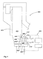
- FIG. 4 is a schematic cross sectional view of another circulating fluidized bed reactor 410 according to another embodiment of the present invention.
- the heat transfer chamber 412' is disposed adjacent the processing or combustion chamber 412 of the reactor, but not in communication with the return duct 413 thereof.
- An inlet opening 444 is provided in a common wall portion 442 between the processing chamber 412 and the heat transfer chamber 412' for introducing solid particles from the internal circulation of the processing chamber into the heat transfer chamber. Additionally an outlet opening 440 is provided in the common wall portion 442 for recirculating solid particles by overflow from the heat transfer chamber 412' into the processing chamber 412.
- the heat transfer chamber is divided into a heat transfer zone 414', including heat transfer surfaces 416 and directly connected to the inlet opening 444, and a second zone 414'' forming a transport zone and being connected to the outlet opening 440, for recycling solid particles into the processing chamber. Both zones are fluidized separately through wind boxes 422' and 422'', respectively.
- a partition wall 446 is provided in the upper part of the heat transfer chamber between upper portions of zones 414' and 414'', for preventing direct flow of particles between the upper portions.
- control unit 434 Similar to control units shown in FIGS. 2 and 3, for controlling the heat recovery in heat transfer chamber 412'.
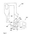
- FIG. 5 is a schematic cross sectional view of another circulating fluidized bed reactor 510 according to still another embodiment of the present invention.
- this reactor 510 having a combustion chamber 512, the heat transfer chamber 512' connected thereto is an ash cooler arranged to receive bed material discharged from the lower part of the combustion chamber 512.
- Heat transfer surfaces 516 are disposed in the heat transfer chamber 512', for recovering heat from the system.
- Bed material is discharged from the combustion chamber 512 into the heat transfer chamber 512' through an opening 544 in a common wall portion 542 close to the bottom 520 of the combustion chamber.
- Another opening 540 is arranged above the opening 544 for allowing gas and fine solid material to flow from the heat transfer chamber 512' into the combustion chamber 512.
- An ash discharge opening 548 is arranged in the bottom of the heat transfer chamber 512', for discharging ash from the system.
- the heat transfer chamber 512' is not divided into two separate zones as solid material is not essentially recycled into the combustion chamber.
- control unit 534 Similar to control units shown in FIGS. 2 to 4, for controlling the heat recovery in heat transfer chamber 512'.
- the form of the reactor or the heat transfer chamber may vary greatly from what has been shown in enclosed exemplary embodiments. It has been indicated that the fluidized bed reactor may be a combustor. The invention may, of course, be applied to other processes, as well, such as heat recovery in connection with hot gas cooling.
- control of heat transfer has been based on monitoring the temperature of heat transfer fluid immediately as it leaves the heat transfer chamber, the control may be based on other monitoring or measurements suitable. Also the need for changing heat transfer rate may be based on monitoring or measurements, at various locations within or outside the system.
- the control system may be designed to be controlled automatically or manually.
Landscapes
- Chemical & Material Sciences (AREA)
- Engineering & Computer Science (AREA)
- Combustion & Propulsion (AREA)
- Chemical Kinetics & Catalysis (AREA)
- Organic Chemistry (AREA)
- Mechanical Engineering (AREA)
- General Engineering & Computer Science (AREA)
- Physics & Mathematics (AREA)
- Thermal Sciences (AREA)
- Devices And Processes Conducted In The Presence Of Fluids And Solid Particles (AREA)
- Fluidized-Bed Combustion And Resonant Combustion (AREA)
- Heat-Exchange Devices With Radiators And Conduit Assemblies (AREA)
- Crucibles And Fluidized-Bed Furnaces (AREA)
- Feeding, Discharge, Calcimining, Fusing, And Gas-Generation Devices (AREA)
Claims (22)
- Verfahren zur Regelung der Wärmeübertragung in einem Wirbelschichtreaktor, der Wirbelschichtreaktor bestehend aus:in welche Wärmeübertragungskammer Fluidisierungsgas kontinuierlich eingeführt wird zur Fluidisierung des Betts von Feststoffpartikeln darin und um die Übertragung von Wärme aus der Wirbelschicht von Feststoffpartikeln auf die Wärmeübertragungsflächen durch die Feststoffpartikel zu veranlassen, die sich in Kontakt mit den Wärmeübertragungsflächen bewegen,einer Wärmeübertragungskammer (12, 312', 412', 512') mit einem Bett (14, 314', 414', 514') von Feststoffpartikeln darin, Mitteln (22, 322', 422', 522') zur Einführung von Fluidisierungsgas in die Wärmeübertragungskammer zur Fluidisierung des Betts aus Feststoffpartikeln darin und Wärmeübertragungsflächen (16, 316, 416, 516) in Verbindung mit dem Bett aus Feststoffpartikeln in der Wärmeübertragungskammer;
gekennzeichnet durch,
während die Strömungsgeschwindigkeit des in die Wärmeübertragungskammer eingeführten Fluidisierungsgases nach einer periodischen Funktion zwischen zwei oder mehreren verschiedenen positiven Strömungsgeschwindigkeiten kontinuierlich variiert wird,
Variieren eines Parameters der Strömungsgeschwindigkeitsfunktion des kontinuierlich in die Wärmeübertragungskammer eingeführten Fluidisierungsgases
fürs Variieren der Fluidisierung des Feststoffpartikelbetts und dadurch zur Regelung der momentanen Wärmeübertragung von Feststoffpartikeln auf die Wärmeübertragungsflächen in der Wärmeübertragungskammer. - Verfahren nach Anspruch 1, dadurch gekennzeichnet, dass die Strömungsgeschwindigkeit des kontinuierlich in die Wärmeübertragungskammer eingeführten Fluidisierungsgases zwischen einer ersten und einer zweiten Strömungsgeschwindigkeit variiert wird, wobei die erste Strömungsgeschwindigkeit höher als die zweite Geschwindigkeit ist, welche erste Strömungsgeschwindigkeit dadurch eine höhere Wärmeübertragung von den Feststoffpartikeln auf die Wärmeübertragungsflächen ergibt als die zweite Strömungsgeschwindigkeit.
- Verfahren nach Anspruch 1, dadurch gekennzeichnet, dass die Strömungsgeschwindigkeit des in die Wärmeübertragungskammer eingeführten Gases periodisch nach einer schrittweisen oder Sägezahnfunktion oder einer Sinusfunktion variiert wird.
- Verfahren nach Anspruch 1, dadurch gekennzeichnet, dass die Strömungsgeschwindigkeit des in die Wärmeübertragungskammer eingeführten Gases periodisch zwischen einer oberen und unteren Grenzgeschwindigkeit variiert wird, wobei für feine Bettmaterialien, wie etwa für das Bettmaterial in einem Reaktor mit zirkulierender Wirbelschicht die "obere" Grenze > 0,2 m/s, bevorzugt > 0,25 m/s und die Differenz zwischen der "oberen" und "unteren" Grenze > 0,1 m/s, bevorzugt > 0,15 m/s ist.
- Verfahren nach Anspruch 1, dadurch gekennzeichnet, dass die Strömungsgeschwindigkeit des in die Wärmeübertragungskammer eingeführten Gases periodisch zwischen einer oberen und unteren Grenzgeschwindigkeit variiert wird, wobei für grobe Materialien, wie etwa Feststoff in einem Aschenkühler die "obere" Grenze > 0,4 m/s, bevorzugt > 0,5 m/s und die Differenz zwischen der "oberen" und "unteren" Grenze > 0,2 m/s, bevorzugt > 0,25 m/s ist.
- Verfahren nach Anspruch 1, dadurch gekennzeichnet, dassdie Strömungsgeschwindigkeit des in die Wärmeübertragungskammer eingeführten Gases periodisch zwischen einer "oberen" und "unteren" Grenzgeschwindigkeit variiert wird undder momentane Wärmeübertragungskoeffizient für von Feststoffpartikeln in der Wärmeübertragungskammer auf die Wärmeübertragungsflächen übertragene Wärme bei der unteren Grenzgeschwindigkeit weniger als 60 % von ihrem Maximalwert und bei der oberen Grenzgeschwindigkeit mehr als 80 % von ihrem Maximalwert ist.
- Verfahren nach Anspruch 1, dadurch gekennzeichnet, dass die Strömung des in die Wärmeübertragungskammer eingeführten Gases zwischen einer Hochgeschwindigkeits-Gasströmung und einer Niedriggeschwindigkeits-Gasströmung variiert wird, und die Zeitdauer der Subperiode Hochgeschwindigkeits-Gasströmung konstant ist, und Zeitdauer der Subperiode Niedriggeschwindigkeits-Gasströmung variiert wird zur Regelung der Wärmeübertragung in der Wärmeübertragungskammer.
- Verfahren nach Anspruch 7, dadurch gekennzeichnet, dass die Zeitdauer der Niedriggeschwindigkeits-Gasströmung < 30 s, bevorzugt zwischen 0 bis 10 s ist.
- Verfahren nach Patentanspruch 1, dadurch gekennzeichnet, dass die Strömung des in die Wärmeübertragungskammer eingeführten Gases zwischen einer Hochgeschwindigkeits-Gasströmung und einer Niedriggeschwindigkeits-Gasströmung variiert wird, und die Zeitdauer einer Subperiode Niedriggeschwindigkeits-Gasströmung konstant ist, und die Zeitdauer einer Subperiode Hochgeschwindigkeits-Gasströmung variiert wird zur Regelung der Wärmeübertragung in der Wärmeübertragungskammer.
- Verfahren nach Patentanspruch 1, dadurch gekennzeichnet, dass die Strömung von Fluidisierungsgas, das in zumindest eine erste und eine zweite Zone der Wärmeübertragungskammer eingeführt wird, getrennt geregelt wird zur Verhinderung von periodischen thermischen Störungen im System.
- Verfahren nach Patentanspruch 1, dadurch gekennzeichnet, dass der Wirbelschichtreaktor weiter eine Aufbereitungskammer, wie eine Brennkammer, in Feststoffpartikel-Fließverbindung mit der Wärmeübertragungskammer umfasst, und in der Brennkammer erzeugte Wärme mittels Wärmeübertragungsflächen in der Wärmeübertragungskammer zurückgewonnen wird.
- Verfahren nach Patentanspruch 1, dadurch gekennzeichnet, dass die Wärmeübertragungskammer ein Aschenkühler ist, und Wärme aus aus dem Wirbelschichtreaktor abgezogener Asche zurückgewonnen wird.
- Verfahren nach Patentanspruch 1, dadurch gekennzeichnet, dass der Wirbelschichtreaktor ein Reaktor mit zirkulierender Wirbelschicht ist, der eine Reaktionskammer und einen Feststoffpartikel-Abscheider umfasst, und die Wärmeübertragungskammer mit einem Rückführkanal verbunden ist, der den Partikelabscheider mit einem unteren Teil der Reaktionskammer verbindet, und in der Brennkammer erzeugte Wärme mittels Wärmeübertragungsflächen in der Wärmeübertragungskammer zurückgewonnen wird.
- Verfahren nach Patentanspruch 1, dadurch gekennzeichnet, dassÄnderung des Wärmeübertragungsbedarfs überwacht wird unddie Mittel zur Einführung von Fluidisierungsgas in die Wärmeübertragungskammer gesteuert werden, um die festgestellte Änderung in Wärmeübertragungsbedarf zu erfassen.
- Verfahren nach Patentanspruch 1, dadurch gekennzeichnet, dassdie Temperatur des Wärmeträgers, wie Heißwasser oder -dampf, die sich durch die Wärmeübertragungsflächen ergibt, überwacht und mit einem voreingestellten Wert verglichen wird, unddie Zeitdauer der Subperioden Hochgeschwiridigkeits-Gasströmung und Subperioden Niedriggeschwindigkeits-Gasströmung nach einem voreingestellten Programm geändert wird, um die gewünschte Wärmeübertragung in der Wärmeübertragungskammer herbeizuführen, damit die Temperatur den voreingestellten Wert erreichen würde.
- Vorrichtung zur Regelung der Wärmeübertragung in einem Wirbelschichtreaktor, der Wirbelschichtreaktor bestehend aus:dadurch gekennzeichnet, dass der Wirbelschichtreaktor des Weitereneiner Wärmeübertragungskammer (12, 312', 412', 512') mit einem Bett (14, 314', 414', 514') von Feststoffpartikeln darin,Mitteln (22, 322', 422', 522') zur kontinuierlichen Einführung von Fluidisierungsgas in die Wärmeübertragungskammer zur Fluidisierung des Betts von Feststoffpartikeln darin, undwärmeübertragungsflächen (16, 316, 416, 516) in Kontakt mit dem Bett von Feststoffpartikeln in der Wärmeübertragungskammer,Mittel (34, 334, 434, 534) aufweist fürs kontinuierliche Variieren der Strömungsgeschwindigkeit von in die Wärmeübertragungskammer eingeführtem Fluidisierungsgas zwischen zwei oder mehreren verschiedenen positiven Strömungsgeschwindigkeiten nach einer periodischen Funktion, welche Mittel fürs Variieren der Fluidisierung Mittel zur Änderung eines Parameters der periodischen Strömungsgeschwindigkeitsfunktion umfassen, zur Regelung der momentanen Wärmeübertragung von Feststoffpartikeln auf die Wärmeübertragungsflächen in der Wärmeübertragungskammer.
- Vorrichtung nach Patentanspruch 16, dadurch gekennzeichnet, dass die Mittel zur Änderung der Fluidisierung des Weiteren umfassenMittel (32, 332) zur Überwachung des Bedarfs zur Änderung der Wärmeübertragung in der Wärmeübertragungskammer, undMittel (38, 338) zur Verarbeitung des festgestellten Bedarfs zur Änderung der Wärmeübertragung zu einer Änderung von Parameter der periodischer Strömungsgeschwindigkeit.
- Vorrichtung nach Patentanspruch 17, dadurch gekennzeichnet, dassdie Mittel zur Überwachung des Bedarfs oder Änderungsbedarfs der Wärmeübertragung in der Wärmeübertragungskammer Temperaturmessmittel umfasssen, die zur Messung der Temperatur von Wärmeträger angeordnet sind, der Wärme aus der Wärmeübertragungskammer heraustransportiert hat.
- Vorrichtung nach Patentanspruch 16, dadurch gekennzeichnet, dassdie Mittel zur Änderung der Fluidisierung ein Ventilorgan (26, 326) umfassen zur Regelung der Geschwindigkeit der Gasströmung, die in die Wärmeübertragungskammer eingeführt wird.
- Vorrichtung nach Patentanspruch 16, dadurch gekennzeichnet, dass der Wirbelschichtreaktor weiter eine Aufbereitungskammer (312, 412, 512), wie etwa eine Brennkammer in Feststoffpartikel-Fließverbindung mit der Wärmeübertragungskammer umfasst.
- Vorrichtung nach Patentanspruch 20, dadurch gekennzeichnet, dass die Wärmeübertragungskammer (512') ein Aschenkühler ist zur Ableitung von grobem festem Bettmaterial aus der Aufbereitungskammer.
- Vorrichtung nach Patentanspruch 16, dadurch gekennzeichnet, dass der Wirbelschichtreaktor ein Reaktor mit zirkulierender Wirbelschicht ist, der eine Reaktionskammer (312) und einen Feststoffpartikel-Abscheider (311) umfasst, und die Wärmeübertragungskammer (312') mit einem Rückführkanal (313) verbunden ist, der den Partikelabscheider mit einem unteren Teil der Reaktionskammer verbindet.
Applications Claiming Priority (1)
| Application Number | Priority Date | Filing Date | Title |
|---|---|---|---|
| PCT/FI1997/000811 WO1999032217A1 (en) | 1997-12-19 | 1997-12-19 | Method and apparatus for controlling heat transfer from solid particles in a fluidized bed |
Publications (2)
| Publication Number | Publication Date |
|---|---|
| EP1062030A1 EP1062030A1 (de) | 2000-12-27 |
| EP1062030B1 true EP1062030B1 (de) | 2003-09-24 |
Family
ID=8556698
Family Applications (1)
| Application Number | Title | Priority Date | Filing Date |
|---|---|---|---|
| EP97948918A Expired - Lifetime EP1062030B1 (de) | 1997-12-19 | 1997-12-19 | Verfahren und vorrichtung zur steuerung des wärmeübergangs von feststoffpartikeln in ein wirbelbett |
Country Status (9)
| Country | Link |
|---|---|
| EP (1) | EP1062030B1 (de) |
| JP (1) | JP3485891B2 (de) |
| AT (1) | ATE250454T1 (de) |
| AU (1) | AU4118299A (de) |
| CA (1) | CA2308500C (de) |
| CZ (1) | CZ299974B6 (de) |
| DE (1) | DE69725188T2 (de) |
| PL (1) | PL190653B1 (de) |
| WO (1) | WO1999032217A1 (de) |
Families Citing this family (4)
| Publication number | Priority date | Publication date | Assignee | Title |
|---|---|---|---|---|
| NL1019983C2 (nl) * | 2002-02-18 | 2003-08-19 | Klarex Beheer B V | Inrichting voor het uitvoeren van een fysisch en/of chemisch proces, zoals een warmtewisselaar, alsmede werkwijze voor het uitvoeren van een fysisch en/of chemisch proces. |
| JP3876362B2 (ja) * | 2002-06-27 | 2007-01-31 | 日立造船株式会社 | 土壌浄化装置 |
| US9163829B2 (en) | 2007-12-12 | 2015-10-20 | Alstom Technology Ltd | Moving bed heat exchanger for circulating fluidized bed boiler |
| WO2009109644A1 (en) * | 2008-03-07 | 2009-09-11 | Shell Internationale Research Maatschappij B.V. | Process for cracking a hydrocarbon feed |
Family Cites Families (9)
| Publication number | Priority date | Publication date | Assignee | Title |
|---|---|---|---|---|
| GB761072A (en) * | 1952-09-25 | 1956-11-07 | Cie Ind De Procedes Et D Appli | Improvements relating to the fluidization of solid granular materials |
| FR1288835A (fr) * | 1961-02-14 | 1962-03-30 | Procédé d'échange de chaleur par surface entre fluides d'une part et matières granuleuses ou pulvérulentes d'autre part | |
| PL103840B1 (pl) * | 1976-11-30 | 1979-07-31 | Akad Ekonom | Sposob wytwarzania pulsujacej warstwy fluidalnej i urzadzenie do wytwarzania pulsujacej warstwy fluidalnej |
| FR2527760B1 (fr) * | 1982-05-26 | 1985-08-30 | Creusot Loire | Procede de controle du transfert de chaleur entre une matiere granulaire et une surface d'echange et echangeur de chaleur pour la mise en oeuvre du procede |
| JPS5922649A (ja) * | 1982-07-28 | 1984-02-04 | Mitsui Eng & Shipbuild Co Ltd | 気相流動層反応器の壁部における粒子塊状化防止方法 |
| US5184671A (en) * | 1987-12-21 | 1993-02-09 | Foster Wheeler Energy Corporation | Fluidized bed heat exchanger and method of operating same |
| US5133297A (en) * | 1991-04-22 | 1992-07-28 | Manufacturing And Technology Conversion International, Inc. | Pulsed atmospheric fluidized bed combustor apparatus and process |
| US5273000A (en) * | 1992-12-30 | 1993-12-28 | Combustion Engineering, Inc. | Reheat steam temperature control in a circulating fluidized bed steam generator |
| FI962653A7 (fi) * | 1996-06-27 | 1997-12-28 | Foster Wheeler Energia Oy | Menetelmä ja laite kiinteistä hiukkasista tapahtuvan lämmön siirtymisen valvomiseksi leijupetireaktorissa |
-
1997
- 1997-12-19 AT AT97948918T patent/ATE250454T1/de not_active IP Right Cessation
- 1997-12-19 WO PCT/FI1997/000811 patent/WO1999032217A1/en not_active Ceased
- 1997-12-19 JP JP2000525199A patent/JP3485891B2/ja not_active Expired - Fee Related
- 1997-12-19 CA CA002308500A patent/CA2308500C/en not_active Expired - Fee Related
- 1997-12-19 EP EP97948918A patent/EP1062030B1/de not_active Expired - Lifetime
- 1997-12-19 DE DE69725188T patent/DE69725188T2/de not_active Expired - Fee Related
- 1997-12-19 PL PL97340660A patent/PL190653B1/pl not_active IP Right Cessation
- 1997-12-19 AU AU41182/99A patent/AU4118299A/en not_active Abandoned
- 1997-12-19 CZ CZ20002086A patent/CZ299974B6/cs not_active IP Right Cessation
Also Published As
| Publication number | Publication date |
|---|---|
| AU4118299A (en) | 1999-07-12 |
| CA2308500C (en) | 2004-03-16 |
| CA2308500A1 (en) | 1999-07-01 |
| JP3485891B2 (ja) | 2004-01-13 |
| PL190653B1 (pl) | 2005-12-30 |
| CZ20002086A3 (cs) | 2001-03-14 |
| ATE250454T1 (de) | 2003-10-15 |
| JP2001526379A (ja) | 2001-12-18 |
| DE69725188D1 (de) | 2003-10-30 |
| PL340660A1 (en) | 2001-02-12 |
| CZ299974B6 (cs) | 2009-01-07 |
| DE69725188T2 (de) | 2004-06-03 |
| EP1062030A1 (de) | 2000-12-27 |
| WO1999032217A1 (en) | 1999-07-01 |
Similar Documents
| Publication | Publication Date | Title |
|---|---|---|
| US6336500B2 (en) | Method and apparatus for controlling heat transfer from solids particles in a fluidized bed | |
| KR100203007B1 (ko) | 유동층 냉각기,유동층 연소 반응기 및 그 작동 방법 | |
| FI104215B (fi) | Menetelmä ja laite lämmön talteenottamiseksi leijukerrosreaktorissa | |
| US4349969A (en) | Fluidized bed reactor utilizing zonal fluidization and anti-mounding pipes | |
| EP1117969B1 (de) | Verfahren und vorrichtung für fliessbettwärmetauscher | |
| FI92157B (fi) | Pyörrekerroslaitteisto | |
| CA1270156A (en) | Fluidized bed steam generator and method of generating steam including a separate recycle bed | |
| CN104837549B (zh) | 具有提高的可靠性的床内固体控制阀 | |
| US5184671A (en) | Fluidized bed heat exchanger and method of operating same | |
| EP1062030B1 (de) | Verfahren und vorrichtung zur steuerung des wärmeübergangs von feststoffpartikeln in ein wirbelbett | |
| CN101883629A (zh) | 流化床以及流化方法 | |
| US20100242361A1 (en) | Fluidized beds having membrane walls and methods of fluidizing | |
| EP1247567B1 (de) | Verfahren zur Steuerung der Reaktionstemperatur innerhalb eines Fliessbettreaktors | |
| US5772969A (en) | Method and apparatus for recovering heat in a fluidized bed reactor | |
| FI85417B (fi) | Foerfarande och anordning foer reglering av temperaturen i en reaktor med fluidiserad baedd. | |
| CA1329338C (en) | Fluidized bed heat exchanger and method of operating same | |
| JPH01219401A (ja) | 燃焼装置の水蒸気発生を調節する方法 | |
| SU1153217A1 (ru) | Способ регулируемого отвода тепла из псевдоожиженного сло | |
| JPH0567875B2 (de) | ||
| JP2600810Y2 (ja) | 石炭ガス化装置 | |
| JP2664942B2 (ja) | 流動床ボイラ | |
| JPH0573965B2 (de) | ||
| WO2012008947A1 (en) | Fluidized beds having membrane walls and methods of fluidizing |
Legal Events
| Date | Code | Title | Description |
|---|---|---|---|
| PUAI | Public reference made under article 153(3) epc to a published international application that has entered the european phase |
Free format text: ORIGINAL CODE: 0009012 |
|
| 17P | Request for examination filed |
Effective date: 20000616 |
|
| AK | Designated contracting states |
Kind code of ref document: A1 Designated state(s): AT DE DK FI FR SE |
|
| GRAH | Despatch of communication of intention to grant a patent |
Free format text: ORIGINAL CODE: EPIDOS IGRA |
|
| GRAS | Grant fee paid |
Free format text: ORIGINAL CODE: EPIDOSNIGR3 |
|
| GRAA | (expected) grant |
Free format text: ORIGINAL CODE: 0009210 |
|
| RIC1 | Information provided on ipc code assigned before grant |
Ipc: 7F 28F 13/10 B Ipc: 7F 28D 13/00 B Ipc: 7F 23C 10/28 B Ipc: 7F 22B 31/00 B Ipc: 7B 01J 8/40 A |
|
| AK | Designated contracting states |
Kind code of ref document: B1 Designated state(s): AT DE DK FI FR SE |
|
| REF | Corresponds to: |
Ref document number: 69725188 Country of ref document: DE Date of ref document: 20031030 Kind code of ref document: P |
|
| PG25 | Lapsed in a contracting state [announced via postgrant information from national office to epo] |
Ref country code: DK Free format text: LAPSE BECAUSE OF FAILURE TO SUBMIT A TRANSLATION OF THE DESCRIPTION OR TO PAY THE FEE WITHIN THE PRESCRIBED TIME-LIMIT Effective date: 20031224 |
|
| REG | Reference to a national code |
Ref country code: SE Ref legal event code: TRGR |
|
| ET | Fr: translation filed | ||
| PLBE | No opposition filed within time limit |
Free format text: ORIGINAL CODE: 0009261 |
|
| STAA | Information on the status of an ep patent application or granted ep patent |
Free format text: STATUS: NO OPPOSITION FILED WITHIN TIME LIMIT |
|
| 26N | No opposition filed |
Effective date: 20040625 |
|
| PGFP | Annual fee paid to national office [announced via postgrant information from national office to epo] |
Ref country code: FI Payment date: 20081112 Year of fee payment: 12 Ref country code: AT Payment date: 20081106 Year of fee payment: 12 |
|
| PGFP | Annual fee paid to national office [announced via postgrant information from national office to epo] |
Ref country code: SE Payment date: 20081117 Year of fee payment: 12 |
|
| PGFP | Annual fee paid to national office [announced via postgrant information from national office to epo] |
Ref country code: FR Payment date: 20081110 Year of fee payment: 12 |
|
| PGFP | Annual fee paid to national office [announced via postgrant information from national office to epo] |
Ref country code: DE Payment date: 20081128 Year of fee payment: 12 |
|
| EUG | Se: european patent has lapsed | ||
| PG25 | Lapsed in a contracting state [announced via postgrant information from national office to epo] |
Ref country code: FI Free format text: LAPSE BECAUSE OF NON-PAYMENT OF DUE FEES Effective date: 20091219 Ref country code: AT Free format text: LAPSE BECAUSE OF NON-PAYMENT OF DUE FEES Effective date: 20091219 |
|
| REG | Reference to a national code |
Ref country code: FR Ref legal event code: ST Effective date: 20100831 |
|
| PG25 | Lapsed in a contracting state [announced via postgrant information from national office to epo] |
Ref country code: FR Free format text: LAPSE BECAUSE OF NON-PAYMENT OF DUE FEES Effective date: 20091231 |
|
| PG25 | Lapsed in a contracting state [announced via postgrant information from national office to epo] |
Ref country code: DE Free format text: LAPSE BECAUSE OF NON-PAYMENT OF DUE FEES Effective date: 20100701 |
|
| PG25 | Lapsed in a contracting state [announced via postgrant information from national office to epo] |
Ref country code: SE Free format text: LAPSE BECAUSE OF NON-PAYMENT OF DUE FEES Effective date: 20091220 |