EP1062045B1 - Dispositif pour le traitement thermique de liquides - Google Patents
Dispositif pour le traitement thermique de liquides Download PDFInfo
- Publication number
- EP1062045B1 EP1062045B1 EP99907610A EP99907610A EP1062045B1 EP 1062045 B1 EP1062045 B1 EP 1062045B1 EP 99907610 A EP99907610 A EP 99907610A EP 99907610 A EP99907610 A EP 99907610A EP 1062045 B1 EP1062045 B1 EP 1062045B1
- Authority
- EP
- European Patent Office
- Prior art keywords
- container
- displacer
- cooling device
- wall
- cooling
- Prior art date
- Legal status (The legal status is an assumption and is not a legal conclusion. Google has not performed a legal analysis and makes no representation as to the accuracy of the status listed.)
- Expired - Lifetime
Links
- 238000010438 heat treatment Methods 0.000 title claims abstract description 45
- 239000007788 liquid Substances 0.000 title claims abstract description 35
- 238000001816 cooling Methods 0.000 claims abstract description 55
- 238000009833 condensation Methods 0.000 claims abstract description 5
- 230000005494 condensation Effects 0.000 claims abstract description 5
- 238000012546 transfer Methods 0.000 claims description 19
- 239000002826 coolant Substances 0.000 claims description 11
- 229910052751 metal Inorganic materials 0.000 claims description 8
- 239000002184 metal Substances 0.000 claims description 8
- 238000002347 injection Methods 0.000 claims description 5
- 239000007924 injection Substances 0.000 claims description 5
- 125000006850 spacer group Chemical group 0.000 claims description 5
- 238000007669 thermal treatment Methods 0.000 claims description 3
- 239000011261 inert gas Substances 0.000 claims description 2
- 238000003780 insertion Methods 0.000 claims description 2
- 230000037431 insertion Effects 0.000 claims description 2
- 239000011159 matrix material Substances 0.000 claims description 2
- 230000013011 mating Effects 0.000 claims 2
- 238000007373 indentation Methods 0.000 claims 1
- 239000000463 material Substances 0.000 claims 1
- 239000007787 solid Substances 0.000 claims 1
- 230000008016 vaporization Effects 0.000 claims 1
- 238000013022 venting Methods 0.000 claims 1
- 238000001704 evaporation Methods 0.000 abstract description 4
- 230000008020 evaporation Effects 0.000 abstract description 3
- 230000000630 rising effect Effects 0.000 abstract description 3
- 239000011800 void material Substances 0.000 abstract 2
- 238000012360 testing method Methods 0.000 description 49
- 238000006073 displacement reaction Methods 0.000 description 8
- 238000011282 treatment Methods 0.000 description 7
- 229910052782 aluminium Inorganic materials 0.000 description 5
- XAGFODPZIPBFFR-UHFFFAOYSA-N aluminium Chemical compound [Al] XAGFODPZIPBFFR-UHFFFAOYSA-N 0.000 description 5
- 238000009434 installation Methods 0.000 description 5
- 239000012080 ambient air Substances 0.000 description 3
- 230000000712 assembly Effects 0.000 description 3
- 238000000429 assembly Methods 0.000 description 3
- 238000010276 construction Methods 0.000 description 3
- 238000009413 insulation Methods 0.000 description 3
- 238000009423 ventilation Methods 0.000 description 3
- 239000012528 membrane Substances 0.000 description 2
- 238000007789 sealing Methods 0.000 description 2
- RYGMFSIKBFXOCR-UHFFFAOYSA-N Copper Chemical compound [Cu] RYGMFSIKBFXOCR-UHFFFAOYSA-N 0.000 description 1
- 238000010521 absorption reaction Methods 0.000 description 1
- 238000013459 approach Methods 0.000 description 1
- 239000003153 chemical reaction reagent Substances 0.000 description 1
- 239000004020 conductor Substances 0.000 description 1
- 238000011109 contamination Methods 0.000 description 1
- 229910052802 copper Inorganic materials 0.000 description 1
- 239000010949 copper Substances 0.000 description 1
- 238000011161 development Methods 0.000 description 1
- 230000018109 developmental process Effects 0.000 description 1
- 230000000694 effects Effects 0.000 description 1
- 238000005485 electric heating Methods 0.000 description 1
- 239000007789 gas Substances 0.000 description 1
- 238000012986 modification Methods 0.000 description 1
- 230000004048 modification Effects 0.000 description 1
- 230000021715 photosynthesis, light harvesting Effects 0.000 description 1
- 238000010926 purge Methods 0.000 description 1
- 230000005855 radiation Effects 0.000 description 1
- 230000000284 resting effect Effects 0.000 description 1
- 230000000717 retained effect Effects 0.000 description 1
- 238000002849 thermal shift Methods 0.000 description 1
Images




Classifications
-
- B—PERFORMING OPERATIONS; TRANSPORTING
- B01—PHYSICAL OR CHEMICAL PROCESSES OR APPARATUS IN GENERAL
- B01D—SEPARATION
- B01D1/00—Evaporating
- B01D1/0011—Heating features
- B01D1/0017—Use of electrical or wave energy
-
- B—PERFORMING OPERATIONS; TRANSPORTING
- B01—PHYSICAL OR CHEMICAL PROCESSES OR APPARATUS IN GENERAL
- B01D—SEPARATION
- B01D5/00—Condensation of vapours; Recovering volatile solvents by condensation
- B01D5/0057—Condensation of vapours; Recovering volatile solvents by condensation in combination with other processes
- B01D5/006—Condensation of vapours; Recovering volatile solvents by condensation in combination with other processes with evaporation or distillation
- B01D5/0063—Reflux condensation
-
- B—PERFORMING OPERATIONS; TRANSPORTING
- B01—PHYSICAL OR CHEMICAL PROCESSES OR APPARATUS IN GENERAL
- B01L—CHEMICAL OR PHYSICAL LABORATORY APPARATUS FOR GENERAL USE
- B01L7/00—Heating or cooling apparatus; Heat insulating devices
-
- G—PHYSICS
- G01—MEASURING; TESTING
- G01N—INVESTIGATING OR ANALYSING MATERIALS BY DETERMINING THEIR CHEMICAL OR PHYSICAL PROPERTIES
- G01N1/00—Sampling; Preparing specimens for investigation
- G01N1/28—Preparing specimens for investigation including physical details of (bio-)chemical methods covered elsewhere, e.g. G01N33/50, C12Q
- G01N1/40—Concentrating samples
- G01N1/4022—Concentrating samples by thermal techniques; Phase changes
- G01N2001/4033—Concentrating samples by thermal techniques; Phase changes sample concentrated on a cold spot, e.g. condensation or distillation
Definitions
- the invention relates to a device for the thermal treatment of Liquids with at least one first container space, which by means of a Heating device for heating and at least partially evaporating the Liquid heat energy can be supplied, as well as with at least a second Container space into which the steam for at least partial condensation insertable and dissipable from the thermal energy by means of a cooling device is, as well as with one or each condensate return channel, which is from the second leads to the first container space.
- the invention is intended to. To be solved, a facility of briefly defined type so that the heat transfer between the container space and the heating device and / or the cooling device is greatly improved.
- the parts of the present Device according to a preferred embodiment in the first place can be commercially available parts
- the outer container for receiving the treating liquid is formed by a larger test tube, during the displacer, which coaxial to a certain depth in the outer container is inserted and held in place by spacers a corresponding test tube of smaller diameter can be formed.
- Facilities of the type specified here can be created with the least effort and realize small costs.
- the specified construction a variety of modifications to adapt to specific use cases accessible.
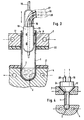
- Fig. 1 leaves in axial section an outer container in the form of a Detect test tube 1 of relatively large diameter, which in a first, lower container space 2 a filling to be treated Contains liquid.
- the test tube 1 is in a with adapted recesses 3 provided heating plate 4, which is traversed by heating medium channels 5, in which, as indicated by dash-dotted arrows, introduced a heating medium and can be removed from there.
- the heating plate 4 can be, for example Be aluminum plate. As a variation of this, it is also possible to enter the Heating plate to embed 4 electric heating coils.
- a cooling device 7 in the form of an aluminum plate, which is provided with openings 8 for the passage of the container section 6 and. which is traversed by coolant channels 9, in which, as well as dash-dotted arrows indicated, a coolant introduced and from there again can be removed so that the located in the area of the cooling device 7 Container section 6 by radiation absorption and by intensive convection in the gap between the container section and the inner wall of the Breakthrough 8 experiences effective cooling.
- a displacement body 10 in the form of a is in the test tube 1 from above another, smaller diameter than the test tube 1 Test tube inserted so far that the lower end of the test tube 10 to extends below the area of the container section 6, the test tube 10 is held coaxially in the test tube 1 by spacers 11, which by elastic rings distributed around the circumference are held on the test tube 10.
- the diameter of the test tubes 1 and 10 are chosen so that between the outer wall of the test tube 10 and the inner wall of the test tube 1 Narrow cylindrical gap space is created, which here is the second container space is designated and has the reference number 12 in the drawing.
- the liquid filling in the test tube 1 within the first container space 2 is heated by supplying heat according to the arrows W H , part of the liquid evaporates on the surface of the liquid filling and is prevented from doing so by the displacer body formed by the test tube 10 , rise freely in the test tube 1 towards its opening and flow out, but is pushed by the test tube 10 in the direction of the inner wall of the test tube 1 cooled by heat removal in accordance with the arrows W K in the gap space 12 forming the second container space and for the intensive flow of the cooled container wall causes where rapid condensation takes place.
- the condensate drops run down again on the inner wall of the test tube 1 and are fed to the liquid filling in the first container space 2.
- FIG. 3 in which the same for corresponding parts Reference numbers used as in Fig. 2 differ from that previously considered embodiment first in that instead of the inner Test tube 10 in the embodiment of FIG. 3 is a closed container 13 serves as a displacer, on its cylindrical outer wall in the area of Container section 6 of the test tube 1 spacer hump 14 formed which are used to adjust the width of the circumferential gap 12 support against the inner wall of the container 1.
- a pipette tube 16 is guided, which is connected to a liquid line 17 is connected.
- Condensate therefore settles on the inner wall of the container 1 as well from the circumferential wall of the displacer 13 and down the gap space 12 returned to the liquid filling of the first container space 2. You want to achieve that the condensate settles only on the inner wall of the container 1, so the performance of the cooling device 7 is set accordingly stronger or it the embodiment of FIG. 1 is given preference.
- FIG 3 also shows between the heating device 4 and the cooling device 7 provided thermal insulation layers 21 and 22 in the form of with Breakthroughs for the passage of the container or test tube 1 provided Insulation.
- Such insulating plates can also be used in the embodiment 1 may be provided.
- the heating device 4 and the cooling device 7 are in a fixed frame, Frame or box with connections for the heating medium channels 5 and Coolant channels 9 for a multiple arrangement of containers or Test tubes 1 and respective displacers 10 and 13 respectively.
- the one forming the second container space Gap space 12 in the container section of the container 1 is not necessarily must be cylindrical, but can also have a conical shape, the opening 8 in the heater 7, the wall of the container 1 in the section delimiting the gap 12 and the outer wall of the Displacer body, which is designated here with 24, correspondingly conical are trained.
- 4 is the displacement body 24 again around a displacement body through which coolant flows, as through the coolant supply and discharge lines 19 and 20 is indicated.
- the lower part of the device is included Recesses 3 for test tubes 1 having heating plate 4 in exactly the same way formed as in the embodiment of FIG. 1.
- the displacer 10, in the area of the container section 6 of the test tube 1 together with whose inner wall delimits the gap space 12, but is not through here Spacers or the like supported against the test tube 1 or centered, but is on a cooling device in the form of a here with 25 designated aluminum plate attached by coolant channels 26th is crossed and which compared to the heating plate 4 and in the Recesses 3 test tubes 1 used in the vertical direction Insert the displacer 10 in the test tubes 1 lowered or Removing the displacer 10 from the container section 6 of the Test tubes 1 can be raised.
- insulation layers 21 and 22 appropriate.
- an opening 27 is formed, on which a ball 28 rests.
- This ball 28 can in cooperation with the Opening 27 serve as a non-return vent valve, if for example through in Fig. 5 not shown facilities at the top of the or each Test tube 1 a tight seal of the annular mouth of the Gap space 12 is provided. Then arises through the supply of heat by means of Heating device 4 in the interior of the test tube 1, an excess pressure, so this through the check valve formed by the parts 27 and 28 relieve the interior of the displacer 10.
- the opening 27 can also serve one over the interior of the Displacer 10 inserted injection needle or pipette access to the To allow container space 2 in the test tube 1 to fill the liquid there bring in or suction from there.
- the Injection needle tip or pipette tip the ball 28 from the mouth of the Opening 27 so that the needle or pipette are guided past the ball 28 can. This state is otherwise in the Fig. 6 considered below for the Expert clearly shown.
- the embodiment according to FIG. 6 again contains recesses 3 a heater 4 used containers, for example test tubes 1, which in the area of an upper container section 6 of one with openings 8 provided, coolant channels 9 having aluminum plate, which the Cooling device 7 forms are surrounded.
- a heater 4 used containers for example test tubes 1, which in the area of an upper container section 6 of one with openings 8 provided, coolant channels 9 having aluminum plate, which the Cooling device 7 forms are surrounded.
- each container 1 is here with 30th designated, test tube-like displacer assigned to the bottom End similar to the embodiment of FIG. 5, an opening 27 and has ball 28 seated on its upper mouth and approximately in the middle Area of its axial extent on the outer surface with one piece molded radial flange 31 is provided.
- This radial flange 31 has one essentially the same outside diameter as one with an external thread Provided upper end edge 32 of the container 1.
- a screw sleeve 33 is the radial flange 31 with the interposition of a sealing ring 34 sealing clamped against the upper edge 32 of the container 1. So you can see that the Gap space 12 in the embodiment of FIG. 6 at its upper end deviating from the previously described embodiments hermetically is completed.
- vent openings 35 Another important task of the vent openings 35 is to Condensate is retained in the gap space 12 by capillary action to prevent if condensate drops form an annular, resting on both boundary walls of the gap 12 Combine liquid filling.
- the inverted funnel-shaped installation wall 36 in has an opening at its center which is large enough to accommodate the Let ball 28 pass through and into the lower part of the displacer 30th to be able to introduce.
- the central opening of the installation wall 36 also allows as the opening 27 at the lower end of the displacer 30 the passage an injection needle or pipette for those already in connection with FIG. 5 explained purposes.
- Cooling device 7 In order to via the ventilation openings 35 in the displacement body 30 Condensing rising vapors safely can be in addition to that Cooling device 7 or instead of it, similar to that considered in Fig. 5 Construction, a cooler device or a further cooling device above of the radial flange 31 of the displacer body 30 act thereon. This In analogy to the relationships of FIG. 5, the cooling device is also shown in FIG. 6 25 designated.
- the interior of the displacer 30 and in particular the interior of the Container 1 completely sealed off from the ambient atmosphere is held.
- Will be a liquid to be treated in the lower container space 2 of the container and the overlying space of the container 1st and also the interior of the displacer is evacuated or by means of a Flushed with inert gas, the equilibrium of the energy supply arises through the heating device and the energy dissipation by the cooling device in the essentially no pressure difference between the aforementioned interiors and the Environment, so that there is a contamination of the container interior mentioned cannot come through the ambient air. Practically, however, arise during treatment, pressure difference and filling and emptying can be accessed from ambient air to the liquid to be treated or treated always be excluded.
- a lock with lock walls 38 and 39 is indicated schematically in the upper region of the displacement body 30.
- These lock walls contain, in the region of the wall of the displacer body 30, tightly connected, pierceable elastic membranes, and further the outer wall of the displacer body 30 is provided with openings in the section between the lock walls 38 and 39 or is recessed.
- An inert purge gas is passed through the space formed between the lock walls 38 and 39, as indicated by the arrows N 2 .
- the arrangement shown prevents steam from escaping from the interior of the device to the environment and also prevents access of ambient air to the interior of the device even when filling or removal is carried out by means of an injection needle.
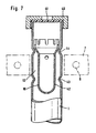
- Fig. 7 shows an embodiment in which the upper edge of the Container 1 is provided with an external thread on which one with a central opening provided screw sleeve 40 with the interposition of a elastic, penetrable membrane 41 is screwed to the interior of the To seal container 1 hermetically.
- the one labeled 42 here Displacer body has a lower condensate drain opening and side Vents in its upper area to prevent one Condensate is held in the gap 12 by capillary action.
- a centering and support of the displacer 42 is in the Embodiment according to Fig. 7 by point or circumferential Curvatures 43 and 44 of the outer wall of the container 1 are made.
- the upper end of the displacer 42 has a shoulder of larger diameter on, against the all-round or point-shaped arch 44 of the wall of the container 1 supports.
- the edge of which extends axially upward be and may be crenellated.
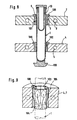
- FIG. 8 is a similar embodiment of a device of the type shown here considered type as shown in Fig. 1. However, that is enough as a container for the to be treated liquid test tube 1 here completely Breakthroughs of the heating plate 4 through which the heating medium channels 5 pass and is supported on a counter bearing 100. In the upper container section 6 that is enough Test tube 1 through the openings 8 of the coolant channels 9 pulled cooling plate 7 through.
- resilient expandable sleeve assembly 101 and 102 provided which from good thermally conductive material, such as aluminum or copper.
- This Sleeve arrangements form enlarged heat conduction contact areas, on the one hand to the outer wall of the container or test tube 1 and on the other hand to the Inner wall of the respective opening of the plate-like heating device 4 or the plate-like cooling device 7.
- a resiliently expandable sleeve assembly 101 between the outer wall of the Container 1 and the inner wall of the opening of the plate-like Cooling device 7 is provided.
- the Sleeve assemblies 101 or 102 of one part in the axial direction several times slotted metal sleeve 103 may be formed, which with areas 104 of their Relocate the inner surface on the outside of the container and with it Areas 105 of their outer surfaces abut the inner opening so that the heat transfer from the plate-like heating device or from the Cooling device 7 by conduction via the metal sleeve 103 to the The outer wall of the container 1 is improved considerably.
- the expert recognizes that compared to the axial slot indicated in Fig.
- the metal sleeve 103 can protrude radially from the upper edge Holding lugs 106 on the top of the heating device or cooling device 7 be supported to prevent that when inserting the test tube or of the container 1 in the resiliently expandable metal sleeve 103 through the Breakthrough of the plate-like heating device or cooling device in question pushed through the wind.
- all-round top Flanges of the embodiment of Fig. 8 are in this drawing figure also designated 106.
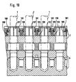
- the plate-like cooling device 7 and also the plate-like heating device 4 each divided into horizontal planes educated.
- the Test tubes or the treatment container 1 heat transfer between the Cooling device 7 and a section of the respective container 1 improving spring expandable sleeve assemblies 101 placed.
- This Sleeve arrangements 101 here have the shape of heat transfer bodies, which are composed of resiliently held sector elements.
- the Heat transfer bodies from the sector elements contain one Outside diameter of the test tubes 1 adapted opening 107 and End faces 108, which on corresponding counter surfaces of the plate-like Cooling device 7 abut.
- the individual sector elements the shape of hollow cylinder sectors, which lead to a metallic hollow cylinder body assembled and by in all-round Grooves 109 inserted spring washers 110 are held together.
- the upward oriented end faces on the metallic hollow cylinder bodies which with corresponding, downward facing surfaces of the upper part of the two-part plate-like heating device 7 cooperate, relatively are small.
- the downward facing faces 108 of the metallic Hollow cylinder bodies 101 are only relatively small annular surfaces Surface area and act with corresponding ring-shaped contact surfaces the upward facing surface of the lower part of the plate-like Cooling device 7 together.
- the individual sector elements are by a coil spring ring 115, which is inserted into a circumferential groove 116 of the heat transfer block is held together and around the outer wall of the test tube 1 clamped together to the thermally conductive contact to the container wall improve.
- the shape of the part of the Heat transfer blocks conforming to the shape of the recess 114 desirably prevents easy rotation of the Test tube 1 opposite the plate-like cooling device 7 or opposite the entire treatment facility.
- the spring expandable specified here Sleeve arrangement in particular as a heat transfer block, between a plate-like heating and / or cooling device and one through an opening this facility or these facilities reaching the container Heat transfer surprisingly improved and the necessary Reducing temperature differences helps and / or the necessary Helps reduce treatment times.
- Figures 8 to 11 have in common that a provided in the upper container area and / or in the lower container area, resiliently expandable sleeve assembly in a variety of Treatment sites for a corresponding number of containers System allows thermal shifts by cooling the cooling device and heating the heating device in opposite directions to each other Compensate horizontal directions, so that such shifts in the Order of magnitude of 1 mm can be easily accommodated without tilting and jamming or even breakage of the container when vertical Insertion or vertical removal and also during treatment too fear.
Landscapes
- Chemical & Material Sciences (AREA)
- Chemical Kinetics & Catalysis (AREA)
- Health & Medical Sciences (AREA)
- Clinical Laboratory Science (AREA)
- Devices For Use In Laboratory Experiments (AREA)
- Food Preservation Except Freezing, Refrigeration, And Drying (AREA)
Claims (15)
- Dispositif pour le traitement thermique de liquides dans des récipients, comprenant un premier compartiment de récipient, auquel de l'énergie calorifique peut être amenée au moyen d'un dispositif de chauffage (4) en forme de plaque pour l'échauffement et au moins l'évaporation partielle du liquide, ainsi qu'un deuxième compartiment de récipient dans lequel la vapeur peut être introduite pour au moins la condensation partielle et duquel de l'énergie calorifique peut être évacuée au moyen d'un dispositif de refroidissement (7) en forme de plaque, ainsi qu'une voie d'écoulement de retour de condensat, resp. une voie d'écoulement de retour de condensat pour chaque compartiment, qui mène du deuxième compartiment de récipient au premier compartiment de récipient, caractérisé en ce que là où un transport de chaleur a lieu, par exemple en sens radial entre le resp. un dispositif de refroidissement (7) en forme de plaque et/ou le resp. un dispositif de chauffage (4) en forme de plaque d'une part, et le resp. un récipient (1) passant à travers une ouverture de ce dispositif de refroidissement resp. de ce dispositif de chauffage d'autre part, un dispositif à douille (101, 102), resp. un dispositif à douille pour chaque compartiment, pouvant être élargi de manière élastique, en matériau bon conducteur de chaleur, est inséré, lequel forme de plus grandes surfaces de contact conductrices de chaleur (104, 105), d'une part vers la paroi du récipient et, d'autre part vers l'ouverture du dispositif de refroidissement resp. du dispositif de chaleur concerné.
- Dispositif suivant la revendication 1, caractérisé en ce que le dispositif à douille (103) est formé par une douille métallique (103) partiellement fendue de manière multiple en sens axial, avec des parties (104) de sa surface intérieure adjacentes à la paroi extérieure du récipient et avec des parties (105) de sa surface extérieure, décalées par rapport à ces parties, adjacentes à la paroi intérieure de l'ouverture.
- Dispositif suivant la revendication 1, caractérisé en ce que le dispositif à douille (101, 102) est formé par un corps métallique cylindrique creux, constitué par des secteurs cylindriques creux (107) maintenus ensemble de manière élastique, dont le diamètre intérieur correspond essentiellement au diamètre extérieur du récipient et dont les surfaces frontales (108) sont adjacentes à des contre-surfaces parallèles du dispositif de refroidissement resp. du dispositif de chauffage (4, 7).
- Dispositif suivant la revendication 1, caractérisé en ce que le dispositif à douille (101, 102) est formé par un bloc métallique de transfert de chaleur constitué d'éléments de secteurs maintenus ensemble de manière élastique, lequel présente une ouverture (113) correspondant à peu près au diamètre extérieur du récipient et est inséré de manière ajustée dans un évidement (114), non cylindrique, notamment à peu près de forme parallélépipède rectangle, du dispositif de refroidissement (7) resp. du dispositif de chauffage, de telle sorte que les surfaces frontales du bloc de transfert de chaleur, par rapport à l'axe longitudinal du récipient, sont adjacentes aux contre-surfaces de l'évidement et que le bloc de transfert de chaleur est arrêté en rotation.
- Dispositif suivant la revendication 3 ou 4, caractérisé en ce que le dispositif de refroidissement (7) resp. le dispositif de chauffage (4) en forme de plaque est formé en deux parties, de sorte que les parties en plaque autour du dispositif à douille sont aptes à être serrées ensemble.
- Dispositif suivant l'une des revendications 2 à 5, caractérisé en ce que les éléments de secteurs du dispositif à douille peuvent être soumis à la tension contre la paroi extérieure du récipient dans une rainure circulaire du dispositif à douille, par insertion d'une bague, notamment d'une rondelle ressort, pouvant être élargie de manière élastique.
- Dispositif suivant l'une des revendications 1 à 6, caractérisé en ce que le premier compartiment de récipient (2) est formé dans un récipient (1) ayant une section de récipient (6) cylindrique ou prismatique ou conique, s'étendant essentiellement de manière verticale vers le haut, dans lequel un corps de déplacement correspondant (10 resp. 13 resp. 24 resp. 30 resp. 42), cylindrique ou prismatique ou conique, plein ou creux, est inséré de telle manière qu'un espace en fente (12) formant le deuxième compartiment de récipient se forme entre la paroi intérieure de la section du réservoir et la paroi extérieure du corps de déplacement, dans lequel de la vapeur de liquide est forcée de s'écouler intensivement sur la paroi intérieure de la section du réservoir, de sorte que le dispositif de chauffage (4) en dessous de la section de réservoir (6) agit sur le réservoir (1) et que dans la partie de la section de réservoir (6), ou à proximité thermique au-dessus de celle-ci, le dispositif de refroidissement (7; 13, 10, 20) agit sur la paroi du récipient comme un bloc de refroidissement muni respectivement d'une ouverture (8) pour la pénétration de la section de réservoir cylindrique ou prismatique ou conique.
- Dispositif suivant la revendication 7, caractérisé en ce que le dispositif de refroidissement comporte un circuit de refroidissement (19, 20 ;26) guidé à travers le corps de déplacement (13 resp. 24) ou à travers un corps de refroidissement (25) couplé thermiquement au corps de déplacement.
- Dispositif suivant la revendication 7 ou 8, caractérisé en ce qu'une pipette (16) ou une aiguille d'injection est guidée ou apte à être guidée à travers le corps de déplacement (10, 13, 30, 42) abaissable dans le récipient (1) pour l'introduction ou l'extraction de liquide traitant dans le récipient (1) ou hors du récipient.
- Dispositif suivant l'une des revendications 7 à 9, caractérisé en ce que des entretoises (11 resp. 14) ou des gradins sont fixés ou formés sur la paroi extérieure du corps de déplacement pour le guidage et le support du corps de déplacement (10 resp. 13) dans la section de récipient (6) par rapport à la paroi intérieure du récipient (1), ou en ce que sur la paroi du récipient (1) des creux ou des gradins (43, 44) sont formés pour le guidage et l'appui du corps de déplacement (42).
- Dispositif selon l'une des revendications 7 à 10, caractérisé en ce qu'au moins une couche d'isolation thermique (21, 22) munie respectivement d'une ouverture pour la pénétration de la section de récipient (6) est prévue entre le dispositif de chauffage (4) et le dispositif de refroidissement (7).
- Dispositif suivant l'une des revendications 7 à 11, caractérisé en ce que le dispositif de chauffage est formé comme une plaque de chauffage (4) prévue avec respectivement un évidement (3) pour le logement de la partie inférieure du récipient.
- Dispositif suivant l'une des revendications 7 à 12, caractérisé en ce que le corps de déplacement creux présente dans sa partie supérieure ledit espace en fente (12) muni des ouvertures d'aération (35) reliant l'espace intérieur du corps de déplacement.
- Dispositif suivant l'une des revendications 7 à 13, caractérisé en ce que le corps de déplacement creux (30) est raccordé de manière étanche sur l'extrémité supérieure du récipient (1), qu'il présente sur son extrémité inférieure une ouverture (27) raccordant l'espace intérieur du corps de déplacement au dit premier compartiment de récipient (2) et, qu'il est accessible sur son extrémité supérieure par l'intermédiaire d'une écluse à gaz inerte (38, 39) (fig. 6).
- Dispositif suivant l'une des revendications 7 à 14, caractérisé par une disposition en rangées ou en matrices de récipients identiques (1) avec des sections de récipients (6) dépassant verticalement, un dispositif de refroidissement (7) comprenant des ouvertures pour les sections de récipient, des corps de déplacement (10 resp. 13 resp. 24 resp. 30, resp. 42) correspondant à ces sections de récipient et d'un dispositif de chauffage (4) prévu pour les parties inférieures du récipient.
Applications Claiming Priority (3)
| Application Number | Priority Date | Filing Date | Title |
|---|---|---|---|
| DE19810833A DE19810833B4 (de) | 1998-03-12 | 1998-03-12 | Einrichtung zur thermischen Behandlung von Flüssigkeiten |
| DE19810833 | 1998-03-12 | ||
| PCT/EP1999/001485 WO1999046048A2 (fr) | 1998-03-12 | 1999-03-08 | Dispositif pour le traitement thermique de liquides |
Publications (2)
| Publication Number | Publication Date |
|---|---|
| EP1062045A2 EP1062045A2 (fr) | 2000-12-27 |
| EP1062045B1 true EP1062045B1 (fr) | 2003-09-03 |
Family
ID=7860704
Family Applications (1)
| Application Number | Title | Priority Date | Filing Date |
|---|---|---|---|
| EP99907610A Expired - Lifetime EP1062045B1 (fr) | 1998-03-12 | 1999-03-08 | Dispositif pour le traitement thermique de liquides |
Country Status (4)
| Country | Link |
|---|---|
| EP (1) | EP1062045B1 (fr) |
| AT (1) | ATE248656T1 (fr) |
| DE (2) | DE19810833B4 (fr) |
| WO (1) | WO1999046048A2 (fr) |
Families Citing this family (6)
| Publication number | Priority date | Publication date | Assignee | Title |
|---|---|---|---|---|
| EP1025905A1 (fr) * | 1999-02-03 | 2000-08-09 | Büchi Labortechnik AG | Dispositif de support pour au moins un récipient d'échantillons dans un évaporateur et procédé d'évaporation |
| GB9915953D0 (en) * | 1999-07-07 | 1999-09-08 | Stem Corp Limited | Improvements relating to multi-station reaction apparatus |
| ATE313070T1 (de) * | 2000-08-22 | 2005-12-15 | Glaxo Group Ltd | Aufbau von rührern und kondensatoren für behältermatrizen sowie verfahren zu deren verwendung |
| DE102009038174B4 (de) * | 2009-08-20 | 2011-07-14 | Wilhelm, Richard, 86529 | Reaktionsvorrichtung zur Sublimation und/oder Thermodesorption und/oder Destillation und/oder Extraktion von Stoffen |
| DE102010040685A1 (de) * | 2010-09-14 | 2012-03-15 | Hamilton Bonaduz Ag | Temperiervorrichtung zur thermischen Verfestigung von Wirkstoff-Beads |
| GB2498820B (en) * | 2012-04-05 | 2014-04-16 | R B Radley & Co Ltd | Condensers |
Family Cites Families (13)
| Publication number | Priority date | Publication date | Assignee | Title |
|---|---|---|---|---|
| GB299084A (en) * | 1927-07-20 | 1928-10-22 | Ig Farbenindustrie Ag | Apparatus for distillation, rectification or evaporation |
| CS165037B1 (fr) * | 1972-03-30 | 1975-11-28 | ||
| DE2409607A1 (de) * | 1974-02-26 | 1975-08-28 | Mueller Rudolf | Probenglaeserkassette fuer auftragegeraete fuer die duennschicht- und papierchromatographie |
| US4340114A (en) * | 1979-11-30 | 1982-07-20 | Lambda Energy Products, Inc. | Controlled performance heat exchanger for evaporative and condensing processes |
| US4511435A (en) * | 1982-02-01 | 1985-04-16 | Rudy Strohschein | Non-flooding distilling column |
| JPH01500805A (ja) * | 1986-09-23 | 1989-03-23 | ウクラインスキー、ナウチノ―イスレドワーチェルスキー、インスチツート、プリロドヌイフ、ガゾフ“ウクルニイガズ” | 接触分離部材用の軸線方向渦巻装置 |
| DE9005806U1 (de) * | 1990-05-22 | 1990-07-26 | Labor Technik Barkey, 4800 Bielefeld | Temperiervorrichtung für Probengefäße |
| US5176799A (en) * | 1991-02-28 | 1993-01-05 | Zymark Corporation | Evaporator with solvent recovery feature |
| DE4131088A1 (de) * | 1991-09-18 | 1993-03-25 | Siemens Ag | Verfahren und einrichtung zum messen der konzentration eines gases im rauchgas |
| US5537508A (en) * | 1993-03-22 | 1996-07-16 | Applied Materials, Inc. | Method and dry vapor generator channel assembly for conveying a liquid from a liquid source to a liquid vaporizer with minimal liquid stagnation |
| DE4316163C2 (de) * | 1993-05-14 | 1995-04-27 | Volker Barkey | Vorrichtung zum Eindampfen von Proben |
| EP0859210A1 (fr) * | 1994-06-01 | 1998-08-19 | Caradon Ideal Limited | Echangeur de chaleur |
| DE19701006C2 (de) * | 1997-01-14 | 1999-08-05 | Colorsal Ges Fuer Farbgroskopi | Vorrichtung und Verfahren zur Rückgewinnung von Lösungsmitteln aus einem verunreinigten Kohlenwasserstoffgemisch |
-
1998
- 1998-03-12 DE DE19810833A patent/DE19810833B4/de not_active Expired - Fee Related
-
1999
- 1999-03-08 AT AT99907610T patent/ATE248656T1/de active
- 1999-03-08 EP EP99907610A patent/EP1062045B1/fr not_active Expired - Lifetime
- 1999-03-08 DE DE59906867T patent/DE59906867D1/de not_active Expired - Lifetime
- 1999-03-08 WO PCT/EP1999/001485 patent/WO1999046048A2/fr not_active Ceased
Also Published As
| Publication number | Publication date |
|---|---|
| DE19810833B4 (de) | 2004-08-12 |
| ATE248656T1 (de) | 2003-09-15 |
| DE59906867D1 (de) | 2003-10-09 |
| DE19810833A1 (de) | 1999-09-16 |
| WO1999046048A3 (fr) | 1999-11-25 |
| WO1999046048A2 (fr) | 1999-09-16 |
| EP1062045A2 (fr) | 2000-12-27 |
Similar Documents
| Publication | Publication Date | Title |
|---|---|---|
| EP3296669B1 (fr) | Ensemble cryostat doté d'un réservoir à vide et d'un objet à refroidir et doté d'un espace creux pouvant être vidé | |
| EP1721684A2 (fr) | Enceinte utilitaire avec dispositif in situ de désinfection | |
| EP1831903B1 (fr) | Commutateur a vide presentant une conductivite elevee | |
| DE60030968T2 (de) | Transfermethode für halbleiterscheiben und haltering | |
| DE69024077T2 (de) | Einrichtung und Verfahren zur Behandlung von Halbleiterscheiben | |
| DE60110061T2 (de) | Thermoelektrischer entfeuchter | |
| DE69301932T2 (de) | Verfahren zur Herstellung einer Drehanoden-Röntgenröhre | |
| DE1589773A1 (de) | Abstuetzung fuer Elektronenfenster | |
| EP1062045B1 (fr) | Dispositif pour le traitement thermique de liquides | |
| DE1093022B (de) | Kuehlvorrichtung fuer Flaechenleistungsgleichrichter auf Halbleiterbasis | |
| DE202014102945U1 (de) | Heiz- und Magnetmodul für eine Vorrichtung zur Aufreinigung von Nukleinsäuren | |
| DE3307572C2 (de) | Probendrehvorrichtung | |
| DE3639760C2 (fr) | ||
| DE69008324T2 (de) | Rotierender Verdampfer. | |
| DE4232556A1 (de) | Verfahren zur Herstellung eines Wärmespeichers, insbesondere Latentwärmespeichers | |
| DE1498552A1 (de) | Ionenquelle | |
| EP0663213B1 (fr) | Enceinte de stérilisation pour la stérilisation à vapeur d'instruments chirurgicaux, implants et similaires | |
| EP1228668A1 (fr) | Chauffage par rayonnement a haut pouvoir de rayonnement infrarouge destine a des chambres de traitement | |
| DE19753505B4 (de) | UV-Modul, beidseitig mit je einer Verschlußbaugruppe ausgerüstet, zum Einsatz in ein Gehäuse oder einen Reaktor | |
| EP3651263A1 (fr) | Système d'accumulation d'énergie | |
| DE19938946C2 (de) | Verfahren und Einrichtung zum Konzentrieren einer Lösungsprobe | |
| DE1265879B (de) | Hochleistungsroentgenroehrenanlage | |
| DE102018123100A1 (de) | Elektronenkanone | |
| DE1489223A1 (de) | Verdampfer | |
| EP0015578A1 (fr) | Dispositif semiconducteur refroidi par ébullition |
Legal Events
| Date | Code | Title | Description |
|---|---|---|---|
| PUAI | Public reference made under article 153(3) epc to a published international application that has entered the european phase |
Free format text: ORIGINAL CODE: 0009012 |
|
| 17P | Request for examination filed |
Effective date: 20001011 |
|
| AK | Designated contracting states |
Kind code of ref document: A2 Designated state(s): AT CH DE GB LI |
|
| 17Q | First examination report despatched |
Effective date: 20011106 |
|
| GRAH | Despatch of communication of intention to grant a patent |
Free format text: ORIGINAL CODE: EPIDOS IGRA |
|
| GRAS | Grant fee paid |
Free format text: ORIGINAL CODE: EPIDOSNIGR3 |
|
| GRAA | (expected) grant |
Free format text: ORIGINAL CODE: 0009210 |
|
| AK | Designated contracting states |
Kind code of ref document: B1 Designated state(s): AT CH DE GB LI |
|
| REG | Reference to a national code |
Ref country code: GB Ref legal event code: FG4D Free format text: NOT ENGLISH |
|
| REG | Reference to a national code |
Ref country code: CH Ref legal event code: NV Representative=s name: KATZAROV S.A. Ref country code: CH Ref legal event code: EP |
|
| REF | Corresponds to: |
Ref document number: 59906867 Country of ref document: DE Date of ref document: 20031009 Kind code of ref document: P |
|
| GBT | Gb: translation of ep patent filed (gb section 77(6)(a)/1977) |
Effective date: 20031217 |
|
| PLBE | No opposition filed within time limit |
Free format text: ORIGINAL CODE: 0009261 |
|
| STAA | Information on the status of an ep patent application or granted ep patent |
Free format text: STATUS: NO OPPOSITION FILED WITHIN TIME LIMIT |
|
| 26N | No opposition filed |
Effective date: 20040604 |
|
| PGFP | Annual fee paid to national office [announced via postgrant information from national office to epo] |
Ref country code: CH Payment date: 20120326 Year of fee payment: 14 |
|
| PGFP | Annual fee paid to national office [announced via postgrant information from national office to epo] |
Ref country code: DE Payment date: 20120323 Year of fee payment: 14 |
|
| PGFP | Annual fee paid to national office [announced via postgrant information from national office to epo] |
Ref country code: GB Payment date: 20120322 Year of fee payment: 14 |
|
| PGFP | Annual fee paid to national office [announced via postgrant information from national office to epo] |
Ref country code: AT Payment date: 20120313 Year of fee payment: 14 |
|
| REG | Reference to a national code |
Ref country code: CH Ref legal event code: PL |
|
| REG | Reference to a national code |
Ref country code: AT Ref legal event code: MM01 Ref document number: 248656 Country of ref document: AT Kind code of ref document: T Effective date: 20130308 |
|
| GBPC | Gb: european patent ceased through non-payment of renewal fee |
Effective date: 20130308 |
|
| REG | Reference to a national code |
Ref country code: DE Ref legal event code: R119 Ref document number: 59906867 Country of ref document: DE Effective date: 20131001 |
|
| PG25 | Lapsed in a contracting state [announced via postgrant information from national office to epo] |
Ref country code: LI Free format text: LAPSE BECAUSE OF NON-PAYMENT OF DUE FEES Effective date: 20130331 Ref country code: AT Free format text: LAPSE BECAUSE OF NON-PAYMENT OF DUE FEES Effective date: 20130308 Ref country code: GB Free format text: LAPSE BECAUSE OF NON-PAYMENT OF DUE FEES Effective date: 20130308 Ref country code: DE Free format text: LAPSE BECAUSE OF NON-PAYMENT OF DUE FEES Effective date: 20131001 Ref country code: CH Free format text: LAPSE BECAUSE OF NON-PAYMENT OF DUE FEES Effective date: 20130331 |