EP1062073B1 - A machine for grinding semi-finished products, particularly billets - Google Patents
A machine for grinding semi-finished products, particularly billets Download PDFInfo
- Publication number
- EP1062073B1 EP1062073B1 EP99911742A EP99911742A EP1062073B1 EP 1062073 B1 EP1062073 B1 EP 1062073B1 EP 99911742 A EP99911742 A EP 99911742A EP 99911742 A EP99911742 A EP 99911742A EP 1062073 B1 EP1062073 B1 EP 1062073B1
- Authority
- EP
- European Patent Office
- Prior art keywords
- grinding
- axis
- frame
- grinding wheel
- billet
- Prior art date
- Legal status (The legal status is an assumption and is not a legal conclusion. Google has not performed a legal analysis and makes no representation as to the accuracy of the status listed.)
- Expired - Lifetime
Links
Images


Classifications
-
- B—PERFORMING OPERATIONS; TRANSPORTING
- B24—GRINDING; POLISHING
- B24D—TOOLS FOR GRINDING, BUFFING OR SHARPENING
- B24D5/00—Bonded abrasive wheels, or wheels with inserted abrasive blocks, designed for acting only by their periphery; Bushings or mountings therefor
- B24D5/06—Bonded abrasive wheels, or wheels with inserted abrasive blocks, designed for acting only by their periphery; Bushings or mountings therefor with inserted abrasive blocks, e.g. segmental
-
- B—PERFORMING OPERATIONS; TRANSPORTING
- B24—GRINDING; POLISHING
- B24B—MACHINES, DEVICES, OR PROCESSES FOR GRINDING OR POLISHING; DRESSING OR CONDITIONING OF ABRADING SURFACES; FEEDING OF GRINDING, POLISHING, OR LAPPING AGENTS
- B24B27/00—Other grinding machines or devices
- B24B27/033—Other grinding machines or devices for grinding a surface for cleaning purposes, e.g. for descaling or for grinding off flaws in the surface
-
- B—PERFORMING OPERATIONS; TRANSPORTING
- B24—GRINDING; POLISHING
- B24B—MACHINES, DEVICES, OR PROCESSES FOR GRINDING OR POLISHING; DRESSING OR CONDITIONING OF ABRADING SURFACES; FEEDING OF GRINDING, POLISHING, OR LAPPING AGENTS
- B24B7/00—Machines or devices designed for grinding plane surfaces on work, including polishing plane glass surfaces; Accessories therefor
- B24B7/10—Single-purpose machines or devices
- B24B7/12—Single-purpose machines or devices for grinding travelling elongated stock, e.g. strip-shaped work
Definitions
- the present invention relates to a machine for grinding semi-finished products, particularly billets, according to the preamble of claim 1.
- the invention further relates to a grinding wheel for the above mentioned machine according to the preamble of claim 7 (see for example US-A-1 582 608).
- a grinding machine having the features outlined above is known from WO-A-9622173.
- Billets produced by rolling generally have surface irregularities mainly due to cracks, scum and other processing residues resulting from the melting and cooling processes.
- the problem upon which the present invention is based is that of providing a machine for grinding semi-finished products, particularly billets, which is designed structurally and functionally so as to overcome all of the problems complained of with reference to the prior art mentioned.
- the grinding wheel according to the invention is defined in claim 7.
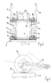
- a machine formed in accordance with the present invention is generally indicated 1 and is intended for grinding semi-finished products such as, for example, foundry billets 2, one of which is shown partially in the drawings.
- the machine 1 comprises a substantially parallelepipedal framework 3 formed by two opposed frames 4 rigidly interconnected by means of four uprights 4c. Each frame 4 is formed by pairs of rigidly-interconnected longitudinal and transverse elements indicated 4a, 4b.
- the billet 2 being ground is guided beneath the framework 3 along an axis of movement indicated by the axis B in Figure 2 and arranged parallel to the longitudinal elements 4a.
- the machine 1 further comprises a first frame and a second frame, indicated 6 and 7, respectively, which are mounted on the framework 3 and are movable relative thereto as explained in detail in the following description.
- the first frame 6 is mounted inside the framework 3 and is also of parallelepipedal shape.
- the frame 6 is formed by pairs of first longitudinal elements 6a connected by first transverse elements 6b and rigidly interconnected by means of first uprights 6c.
- each longitudinal element 4a of the framework 3 At one end of each longitudinal element 4a of the framework 3, at the same end of the framework, a respective arm 8 is articulated about a corresponding pin 8a projecting inside the framework.
- Each arm 8 is in turn articulated at its opposite axial end to a central portion of the respective first longitudinal element 6a of the first frame 6, by means of a corresponding pin 9.
- the arms 8 thus constitute a parallelogram device for moving the first frame 6 relative to the framework 3.
- a pair of actuators such as, for example, two hydraulic jacks 10 shown schematically in Figure 1, is provided for moving the first frame 6.
- Each jack 10 is mounted on a support element 11 extending from the respective upper longitudinal element 4a of the framework 3 and has a rod 12 acting on the first frame 6 in the region of the points of articulation to the arms 8.
- the second frame 7 is mounted inside the first frame 6 and has a similar parallelepipedal shape.
- the frame 7 is formed by a pair of opposed end structures rigidly interconnected by means of uprights 7c. Each end structure is formed by pairs of rigidly interconnected second longitudinal elements 7a and second transverse elements 7b.
- the lower end of the second frame 7 also has connecting cross members 13 preferably formed by parallel and spaced-apart channel-sections.
- the cross-members 13 serve to support two pairs of supports 14 with bearings 15 between which two respective shafts 16, 17 are supported for rotation.
- a respective circular grinding wheel 18, 19 is keyed to each shaft 16, 17.
- Each shaft 16, 17 is also arranged, at one of its ends, for coupling to a respective pulley, not shown, for rotating the corresponding grinding wheel 18, 19 about its axis of rotation, indicated M1, M2 respectively in Figure 2, by means of a belt transmission.
- the belt transmissions are driven by respective electric motors 20 of which only one is shown in Figure 3.
- the motors 20 are fixed to a support plate 20a provided on the upper end of the second frame 7.
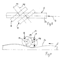
- the grinding wheels 18, 19 are positioned, relative to the second frame 7, with parallel axes of rotation M1 and M2 which are inclined angularly to an axis transverse the axis B of movement of the billet 2.
- the transverse axis is parallel to the articulation axis of the pins 9, which is indicated K in Figure 2, and which is perpendicular to the direction of movement B.
- the angle at which the axis M2 (or M1) is inclined to the axis K is indicated C in Figure 2.
- the angle C may have values of between 5° and 45° and the value selected is preferably 30°.
- the second frame 7 is also mounted for pivoting on the first frame 6 about an axis K1 parallel to the axis K.
- the second frame 7 has supports 21 which are fixed in central positions on the second longitudinal elements 7a of the upper end of the frame 7 and are intended to be engaged on corresponding pins 9 for rotation about the axis K1.
- the interaxial spacing D between the rotation axes M1, M2 of the grinding wheels 18, 19 is arranged symmetrically with respect to the pivot axis K1 so that the loads on the pivoting frame 7, which are due mainly to the weight of the grinding wheels themselves, are distributed in a balanced manner relative to the pivot axis K1.
- pivot axis K1 of the second frame is spaced from the axes of rotation M1, M2 of the grinding wheels 18, 19 on the opposite side to the working plane of the grinding wheels identified by the surface 2a of the billet.
- Each grinding wheel 18, 19 comprises a central hub 22 which is intended to be keyed to the corresponding shaft 16, 17 and on which a ring of abrasive material is mounted.
- the ring is of the type with an interrupted edge and is thus composed of a plurality of structurally independent grinding-wheel sectors 23. More particularly, the grinding wheel comprises six identical sectors 23 each of which is defined peripherally by edge profiles 24.
- the profiles are inclined angularly to the axis of rotation M1, M2 of the grinding wheel, as can be seen in Figure 7.
- the angle of inclination, indicated T, selected for the edge 24 is preferably between 10° and 20°.
- Each abrasive sector 23 is restrained on the hub 22 by means of a pair of jaws 25 clamped by screws 26 extending through the hub. It will be noted that each grinding-wheel sector 23 is spaced from the adjacent sectors peripherally by a distance indicated S in Figure 7.
- the grinding wheels 18, 19 are moved, by means of the parallelogram device operated by the jacks 10, into contact with the surface 2a of the billet 2 being ground.
- the billet 2 is guided beneath the framework 3 along the axis B with a sliding movement relative to the grinding wheels 18, 19 which in turn are rotated about their own axes M1 and M2 by means of the motors 20.
- the surface 2a of the billet is ground throughout its width during the forward movement of the billet, as a result of the contributions of the grinding surfaces of both grinding wheels, as shown schematically in Figure 8.
- This advantageously enables billets having cross-sections of much greater width than the abrasive face of the grinding wheel to be ground in a single forward run of the billet.
- Figure 4 shows, in continuous outline, one of the grinding wheels 18, 19 placed in contact with a large billet 2 (for example having a cross-section of 200-200 mm) and, in broken outline, the grinding wheel in conditions of maximum wear (minimum diameter of the abrasive ring) in contact with the surface of a smaller billet (for example, with a cross-section of 40x40 mm).
- grinding wheels having sectors with edge profiles which are inclined to the axis of the grinding wheel enables the abrasive surface to penetrate the billet better and, in addition, the contact between the surface of the billet and the edge takes place more gradually than with conventional grinding wheels which have edge profiles parallel to the axis of the grinding wheel and in which each grinding-wheel sector consequently strikes the billet with the entire front of the edge during rotation.
- the use of grinding wheels with inclined edge profiles advantageously improves grinding penetration as well as achieving more uniform power absorption, at the same time preventing power-absorption peaks when the edge profile contacts the surface of the billet.
- the abrasive material of the billet wears more evenly, optimizing the useful life of the grinding-wheel sectors.
- the invention thus solves the problem set, achieving the aforementioned advantages in comparison with known solutions.
Landscapes
- Engineering & Computer Science (AREA)
- Mechanical Engineering (AREA)
- Grinding Of Cylindrical And Plane Surfaces (AREA)
- Forging (AREA)
Applications Claiming Priority (3)
| Application Number | Priority Date | Filing Date | Title |
|---|---|---|---|
| ITPD980052 ITPD980052A1 (it) | 1998-03-13 | 1998-03-13 | Macchina per la molatura di semilavorati, in particolare di billette |
| ITPD980052 | 1998-03-13 | ||
| PCT/EP1999/001437 WO1999047305A1 (en) | 1998-03-13 | 1999-03-05 | A machine for grinding semi-finished products, particularly billets |
Publications (2)
| Publication Number | Publication Date |
|---|---|
| EP1062073A1 EP1062073A1 (en) | 2000-12-27 |
| EP1062073B1 true EP1062073B1 (en) | 2002-01-16 |
Family
ID=11392097
Family Applications (1)
| Application Number | Title | Priority Date | Filing Date |
|---|---|---|---|
| EP99911742A Expired - Lifetime EP1062073B1 (en) | 1998-03-13 | 1999-03-05 | A machine for grinding semi-finished products, particularly billets |
Country Status (5)
| Country | Link |
|---|---|
| EP (1) | EP1062073B1 (it) |
| AU (1) | AU3031799A (it) |
| DE (1) | DE69900674D1 (it) |
| IT (1) | ITPD980052A1 (it) |
| WO (1) | WO1999047305A1 (it) |
Families Citing this family (2)
| Publication number | Priority date | Publication date | Assignee | Title |
|---|---|---|---|---|
| JP3049056B1 (ja) | 1998-07-02 | 2000-06-05 | 日本電気通信システム株式会社 | 移動体通信網の加入者デ―タ制御方法 |
| JP2008119819A (ja) * | 2006-10-20 | 2008-05-29 | Jtekt Corp | 凹部入り砥石の製造方法 |
Family Cites Families (4)
| Publication number | Priority date | Publication date | Assignee | Title |
|---|---|---|---|---|
| US1582608A (en) * | 1924-04-28 | 1926-04-27 | Bridgeport Safety Emery Wheel | Sectional grinding wheel |
| DE3524561A1 (de) * | 1985-07-10 | 1987-02-05 | Egon Evertz | Vorrichtung zum schleifen |
| SE9500116L (sv) * | 1995-01-16 | 1996-07-17 | Danieli Centro Maskin Spa | Förfarande vid slipning av företrädesvis ämnen och anordning för utövning av förfarandet |
| JPH09193024A (ja) * | 1996-01-16 | 1997-07-29 | Musashi Seimitsu Ind Co Ltd | 研削砥石 |
-
1998
- 1998-03-13 IT ITPD980052 patent/ITPD980052A1/it unknown
-
1999
- 1999-03-05 AU AU30317/99A patent/AU3031799A/en not_active Abandoned
- 1999-03-05 WO PCT/EP1999/001437 patent/WO1999047305A1/en not_active Ceased
- 1999-03-05 EP EP99911742A patent/EP1062073B1/en not_active Expired - Lifetime
- 1999-03-05 DE DE69900674T patent/DE69900674D1/de not_active Expired - Lifetime
Also Published As
| Publication number | Publication date |
|---|---|
| DE69900674D1 (de) | 2002-02-21 |
| ITPD980052A1 (it) | 1999-09-13 |
| WO1999047305A1 (en) | 1999-09-23 |
| EP1062073A1 (en) | 2000-12-27 |
| AU3031799A (en) | 1999-10-11 |
Similar Documents
| Publication | Publication Date | Title |
|---|---|---|
| US2807123A (en) | Grinding machines and the like | |
| CN111571356A (zh) | 一种可适用于不同规格的工字梁去毛刺装置 | |
| CA2054414A1 (en) | Apparatus for removing burrs from metallic workpieces | |
| GB2160149A (en) | Rotary tool of the cutting or facing-head type | |
| WO2003028968A1 (en) | Facing machine for hard-fired ceramic tiles | |
| DE4436148C1 (de) | Verfahren und Vorrichtung zum seitlichen Planieren von Ziegelformlingen und/oder Ziegeln | |
| RU2051019C1 (ru) | Способ шлифования деревянных изделий и устройство для его осуществления | |
| HU212999B (en) | Belt grinding aggregate and rail grinding machine for grinding the unevennesses of the railhead surface of one or both rails of a track | |
| CN118003210A (zh) | 一种轨道轧辊在线磨削修复机构 | |
| EP1062073A1 (en) | A machine for grinding semi-finished products, particularly billets | |
| CN201049434Y (zh) | 一种适用于棱面或弧面的抛光机械 | |
| CN115106880A (zh) | 一种钢板加工用毛刺打磨装置 | |
| CN201124332Y (zh) | 手扶摇臂悬挂式砂轮机 | |
| CN217528780U (zh) | 一种矫直机自动清辊装置 | |
| EP0242845B1 (en) | Abrasive-supporting head for honing machines | |
| JPH0618646B2 (ja) | ロ−ルクロス式圧延機 | |
| KR101129949B1 (ko) | 봉 형강용 절단기의 블레이드 구조체 | |
| KR100805704B1 (ko) | 롤러 컨베이어의 롤러 연마장치 | |
| CN218964869U (zh) | 一种自动打磨机 | |
| KR101044763B1 (ko) | 롤 이동시 쵸크의 회전이 가능한 롤통 장치 | |
| CN219945549U (zh) | 一种去毛刺装置 | |
| CN224088738U (zh) | 能够对铜合金棒材进行自动抛光的设备 | |
| JP2001047353A (ja) | スラブの研削装置及び研削方法、該研削装置を備えたfms | |
| CN219945684U (zh) | 一种有色金属压延材的打磨装置 | |
| KR100660203B1 (ko) | 스트립 압연 품질을 향상시킨 조질 압연기 및 그에사용되는 백업 롤 |
Legal Events
| Date | Code | Title | Description |
|---|---|---|---|
| PUAI | Public reference made under article 153(3) epc to a published international application that has entered the european phase |
Free format text: ORIGINAL CODE: 0009012 |
|
| 17P | Request for examination filed |
Effective date: 20000821 |
|
| AK | Designated contracting states |
Kind code of ref document: A1 Designated state(s): DE ES FI FR GB IT SE |
|
| GRAG | Despatch of communication of intention to grant |
Free format text: ORIGINAL CODE: EPIDOS AGRA |
|
| 17Q | First examination report despatched |
Effective date: 20010426 |
|
| GRAG | Despatch of communication of intention to grant |
Free format text: ORIGINAL CODE: EPIDOS AGRA |
|
| GRAH | Despatch of communication of intention to grant a patent |
Free format text: ORIGINAL CODE: EPIDOS IGRA |
|
| GRAH | Despatch of communication of intention to grant a patent |
Free format text: ORIGINAL CODE: EPIDOS IGRA |
|
| GRAA | (expected) grant |
Free format text: ORIGINAL CODE: 0009210 |
|
| REG | Reference to a national code |
Ref country code: GB Ref legal event code: IF02 |
|
| AK | Designated contracting states |
Kind code of ref document: B1 Designated state(s): DE ES FI FR GB IT SE |
|
| PG25 | Lapsed in a contracting state [announced via postgrant information from national office to epo] |
Ref country code: FI Free format text: LAPSE BECAUSE OF FAILURE TO SUBMIT A TRANSLATION OF THE DESCRIPTION OR TO PAY THE FEE WITHIN THE PRESCRIBED TIME-LIMIT Effective date: 20020116 |
|
| REF | Corresponds to: |
Ref document number: 69900674 Country of ref document: DE Date of ref document: 20020221 |
|
| PGFP | Annual fee paid to national office [announced via postgrant information from national office to epo] |
Ref country code: FR Payment date: 20020329 Year of fee payment: 4 |
|
| PG25 | Lapsed in a contracting state [announced via postgrant information from national office to epo] |
Ref country code: SE Free format text: LAPSE BECAUSE OF FAILURE TO SUBMIT A TRANSLATION OF THE DESCRIPTION OR TO PAY THE FEE WITHIN THE PRESCRIBED TIME-LIMIT Effective date: 20020416 |
|
| PG25 | Lapsed in a contracting state [announced via postgrant information from national office to epo] |
Ref country code: DE Free format text: LAPSE BECAUSE OF FAILURE TO SUBMIT A TRANSLATION OF THE DESCRIPTION OR TO PAY THE FEE WITHIN THE PRESCRIBED TIME-LIMIT Effective date: 20020417 |
|
| ET | Fr: translation filed | ||
| PG25 | Lapsed in a contracting state [announced via postgrant information from national office to epo] |
Ref country code: ES Free format text: LAPSE BECAUSE OF FAILURE TO SUBMIT A TRANSLATION OF THE DESCRIPTION OR TO PAY THE FEE WITHIN THE PRESCRIBED TIME-LIMIT Effective date: 20020730 |
|
| PLBE | No opposition filed within time limit |
Free format text: ORIGINAL CODE: 0009261 |
|
| STAA | Information on the status of an ep patent application or granted ep patent |
Free format text: STATUS: NO OPPOSITION FILED WITHIN TIME LIMIT |
|
| 26N | No opposition filed | ||
| PG25 | Lapsed in a contracting state [announced via postgrant information from national office to epo] |
Ref country code: GB Free format text: LAPSE BECAUSE OF NON-PAYMENT OF DUE FEES Effective date: 20030305 |
|
| GBPC | Gb: european patent ceased through non-payment of renewal fee |
Effective date: 20030305 |
|
| PG25 | Lapsed in a contracting state [announced via postgrant information from national office to epo] |
Ref country code: FR Free format text: LAPSE BECAUSE OF NON-PAYMENT OF DUE FEES Effective date: 20031127 |
|
| REG | Reference to a national code |
Ref country code: FR Ref legal event code: ST |
|
| PG25 | Lapsed in a contracting state [announced via postgrant information from national office to epo] |
Ref country code: IT Free format text: LAPSE BECAUSE OF NON-PAYMENT OF DUE FEES Effective date: 20050305 |