EP1062086B1 - Hydraulisches system für eine presse - Google Patents
Hydraulisches system für eine presse Download PDFInfo
- Publication number
- EP1062086B1 EP1062086B1 EP98917839A EP98917839A EP1062086B1 EP 1062086 B1 EP1062086 B1 EP 1062086B1 EP 98917839 A EP98917839 A EP 98917839A EP 98917839 A EP98917839 A EP 98917839A EP 1062086 B1 EP1062086 B1 EP 1062086B1
- Authority
- EP
- European Patent Office
- Prior art keywords
- primary side
- flow amplifier
- hydraulic system
- press
- oil
- Prior art date
- Legal status (The legal status is an assumption and is not a legal conclusion. Google has not performed a legal analysis and makes no representation as to the accuracy of the status listed.)
- Expired - Lifetime
Links
- XLYOFNOQVPJJNP-UHFFFAOYSA-N water Substances O XLYOFNOQVPJJNP-UHFFFAOYSA-N 0.000 claims description 7
- 238000000034 method Methods 0.000 description 2
- 239000002245 particle Substances 0.000 description 2
- 238000007789 sealing Methods 0.000 description 2
- QVGXLLKOCUKJST-UHFFFAOYSA-N atomic oxygen Chemical compound [O] QVGXLLKOCUKJST-UHFFFAOYSA-N 0.000 description 1
- 238000000354 decomposition reaction Methods 0.000 description 1
- 230000007423 decrease Effects 0.000 description 1
- 230000000694 effects Effects 0.000 description 1
- 230000007062 hydrolysis Effects 0.000 description 1
- 238000006460 hydrolysis reaction Methods 0.000 description 1
- 230000003647 oxidation Effects 0.000 description 1
- 238000007254 oxidation reaction Methods 0.000 description 1
- 230000001590 oxidative effect Effects 0.000 description 1
- 229910052760 oxygen Inorganic materials 0.000 description 1
- 239000001301 oxygen Substances 0.000 description 1
- 238000005086 pumping Methods 0.000 description 1
Images

Classifications
-
- B—PERFORMING OPERATIONS; TRANSPORTING
- B30—PRESSES
- B30B—PRESSES IN GENERAL
- B30B15/00—Details of, or accessories for, presses; Auxiliary measures in connection with pressing
- B30B15/16—Control arrangements for fluid-driven presses
-
- F—MECHANICAL ENGINEERING; LIGHTING; HEATING; WEAPONS; BLASTING
- F15—FLUID-PRESSURE ACTUATORS; HYDRAULICS OR PNEUMATICS IN GENERAL
- F15B—SYSTEMS ACTING BY MEANS OF FLUIDS IN GENERAL; FLUID-PRESSURE ACTUATORS, e.g. SERVOMOTORS; DETAILS OF FLUID-PRESSURE SYSTEMS, NOT OTHERWISE PROVIDED FOR
- F15B1/00—Installations or systems with accumulators; Supply reservoir or sump assemblies
- F15B1/26—Supply reservoir or sump assemblies
-
- F—MECHANICAL ENGINEERING; LIGHTING; HEATING; WEAPONS; BLASTING
- F15—FLUID-PRESSURE ACTUATORS; HYDRAULICS OR PNEUMATICS IN GENERAL
- F15B—SYSTEMS ACTING BY MEANS OF FLUIDS IN GENERAL; FLUID-PRESSURE ACTUATORS, e.g. SERVOMOTORS; DETAILS OF FLUID-PRESSURE SYSTEMS, NOT OTHERWISE PROVIDED FOR
- F15B3/00—Intensifiers or fluid-pressure converters, e.g. pressure exchangers; Conveying pressure from one fluid system to another, without contact between the fluids
Definitions
- This invention relates to a hydraulic system for a press comprising a press ram, at least one main press cylinder with a primary side for producing press thrust and a device for returning the press ram.
- Hydraulic systems for a press for example a bale press, comprise today pumps, valves, at least one cylinder, press ram and tank for the hydraulic medium, which usually is oil.
- the different parts are connected by hoses and pipes to bring about the desired function.
- the tank usually is located above a main press cylinder, which in its turn is attached to a press ram. To the press ram is also attached a device for returning the press ram.
- the returning device can be, for example, at least one separate return cylinder alternatively located in the main press cylinder, which thereby is double-acting.
- the oil flows from the tank via at least one valve, for rapid filling, into the primary side of the main press cylinder, while the press ram is lowered to the object to be pressed, for example a pulp bale.
- the press ram produces a gradually increasing pressure against the object.
- oil is pumped from the tank into the primary side of the main press cylinder.
- Another object of the tank is to take up variations in the oil level during the movements of the press ram.
- the tank In order to obtain pressure balance in the tank at rapid level variations, the tank is via a filter connected to the atmosphere. Large air volumes pass through the filters. The filter is close-meshed, in order to prevent particles from the air from following along into the tank and contaminate the oil. The filter, therefore, must have high flow capacity, because pressure variations in the tank shall not be permitted when the oil level rapidly changes.
- the present state of art has the problem, that hydrolysis causes decomposition of sealings.
- the air passing through the air filter takes along moisture which is absorbed by the oil.
- the moisture causes hydrolisis damages on the sealings.
- Another problem is, that the oil is disintegrated by oxidation.
- the oxygen oxidizing the oil originates both from the moisture and from the air in the oil.
- the air filter as such also causes problems. Since it must be close-meshed, it easily gets clogged.
- the large tank which must be located above the main press cylinder so that the oil can flow into the primary side thereof, implies a high structure.
- a hydraulic system for a press with a main cylinder with a primary side and a device for returning the press ram, further comprising a pressure intensifier is known from document US-A-4 924 671.
- the problems are solved in that a flow amplifier operating in counterphase to the main press cylinder is provided in the hydraulic system.
- the oil is pressed from the device for returning the press ram, for example the return cylinders, to the flow amplifier, which presses the oil into the primary side of the main press cylinder.
- the dead weight of the press ram can thereby be utilized for amplifying the filling on the secondary side of the main press cylinder, which according to the known state of art is not possible.
- the flow amplifier implies, that rapid variations in the oil level, for example in a tank, are avoided.
- the rapid level variations could result in that moisture, air and particles from the air could get into the oil.
- At least the part between the flow amplifier and primary side of the main press cylinder is closed. Since the supply of the oil to the primary side of the main press cylinder thereby takes place under pressure, a higher flow rate and smaller valve size than at the known state of art can be achieved.
- substantially the entire hydraulic system is closed.
- Necessary pumps are also supplied from the closed part of the hydraulic system.
- only a small tank is required for compensating for heat expansion and leakage oil.
- the total oil amount in the system can be reduced to, for example, one third of the oil volume required by known technique.
- the oil can be de-aired and de-humidified, while substantially no new air and moisture is supplied to the oil.
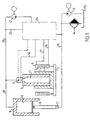
- Fig. 1 shows a hydraulic system for a press comprising a main press cylinder 1 with a primary side 21, a press ram 2, a valve 3 and a device for returning the press ram, where the returning device is located in at least one separate return cylinder 4.
- the return cylinders comprise each a double-acting piston 5 with a large active piston area acting on the primary side 6 of the return cylinders and a small active piston area acting on the secondary side 7 of the return cylinders.
- the hydraulic system further comprises a flow amplifier 8 with a piston arrangement 9, for example a double-acting piston ortwo connected pistons comprising a large active piston area acting on the primary side 10 of the flow amplifier and a small piston area acting on the secondary side 11 of the flow amplifier.
- the large piston area shall be at least 10 times and preferably 20-30 times larger than the small piston area.
- a main pump 12 for pumping hydraulic medium, preferably oil, at least one pump 13 for maintaining overpressure, return of oil and replacing possible leaked oil, and a water and air trap 14 working toward an atmospheric tank 15 are provided, in addition to lines 16, 17, 18, 19 and 20, which connect the various components directly or via a valve plate 24.
- Fig. 2 shows a hydraulic system for a press where, contrary to the embodiment shown in Fig. 1, the return device is located in the main press cylinder 1, which is double-acting and comprises a large active piston area acting on the primary side 21 and a small active piston area acting on the secondary side 22. There is further a line 23, which via the valve plate 24 and the line 16 connects the secondary side 22 of the main press cylinder with the secondary side 11 of the flow amplifier.
- the press ram 2 in the hydraulic system according to Fig. 1 is lowered to the object to be pressed, for example a pulp bale, in that the hydraulic medium via the line 17 is pumped into the primary side 6 of the return cylinders, while the hydraulic medium via the line 16 and valve plate 24 by means of the force transferred by the pistons 5 of the return cylinders is pressed into the secondary side 11 of the flow amplifier.
- the press ram 2 contributes to this force by its dead weight.
- the force acting on the secondary side 11 of the flow amplifier is transferred via the piston arrangement 9 of the flow amplifier to the primary side 10.
- the hydraulic medium is pressed via the line 19 and valve 3 from the primary side 10 of the flow amplifier into the primary side 21 of the main press cylinder.
- the total stroke volume of the return cylinders on the secondary side 7 shall be greater than the stroke volume of the flow amplifier on the secondary side 11.
- valve 3 When the return cylinders 4 cannot any longer lower the press ram 2 toward the pulp bale, i.e. when a predetermined maximum pressure in the primary side 6 of the return cylinders has been achieved, the valve 3 is closed and the hydraulic medium is pumped into the primary side 21 of the main press cylinder via the line 18 while at the same time the hydraulic medium continues to be pumped into the primary side 6 of the return cylinders via the line 17.
- the hydraulic medium in the primary side 21 of the main press cylinder is pressed, while the press ram 2 is being lifted, via the valve 3 and line 19 to the primary side 10 of the flow amplifier.
- the force acting on the secondary side 11 of the flow amplifier is transferred by the piston arrangement 9 of the flow amplifier to the primary side 10.
- the hydraulic medium is pressed via the line 19 and valve 3 from the primary side 10 of the flow amplifier into the primary side 21 of the main press cylinder.
- the stroke volume of the main press cylinder on the secondary side 22 shall be greater than the stroke volume of the flow amplifier on the secondary side 11.
- the valve 3 When the dead weight of the press ram cannot any longer lower the press ram 2 toward the pulp bale, i.e. when a predetermined maximum pressure has been achieved in the secondary side 22 of the main press cylinder, the valve 3 is closed, and the hydraulic medium is pumped into the primary side 21 of the main press cylinder via the line 18.
- the hydraulic medium is pumped via the line 23 into the secondary side 22 of the main press cylinder.
- the hydraulic medium in the primary side 21 of the main press cylinder is pressed, while the press ram 2 is being lifted, via the valve 3 and line 19 to the primary side 10 of the flow amplifier.
- the trap 14 is connected to the atmospheric tank 15, from which the pump 13 pumps the hydraulic medium, which is substantially free of water and air, to the hydraulic system.
- the pump 13 is connected to the secondary side 11 of the flow amplifier.
Landscapes
- Engineering & Computer Science (AREA)
- Mechanical Engineering (AREA)
- Physics & Mathematics (AREA)
- Fluid Mechanics (AREA)
- General Engineering & Computer Science (AREA)
- Press Drives And Press Lines (AREA)
- Control Of Presses (AREA)
Claims (5)
- Hydraulisches System für eine Presse umfassend einen Pressenstößel (2), zumindest einen Haupt-Presszylinder (1) mit einer primären Seite (21) zum Erzeugen von Pressschub und eine Einrichtung zum Zurückführen des Pressenstößels, mit zumindest einem Strömungsverstärker (8) mit einer primären und einer sekundären Seite (10, 11) umfassend eine Kolbenanordnung (9) mit einer großen aktiven Kolbenfläche, welche auf die primäre Seite (10) des Strömungsverstärkers wirkt, und einer kleinen aktiven Kolbenfläche, welche auf die sekundäre Seite (11) des Strömungsverstärkers wirkt, dadurch gekennzeichnet, dass die primäre Seite (10) des Strömungsverstärkers an die primäre Seite (21) des Haupt-Presszylinders angeschlossen ist, und die sekundäre Seite (11) des Strömungsverstärkers an die zurückführende Einrichtung angeschlossen ist, und dass zumindest der Teil zwischen der primären Seite (10) des Strömungsverstärkers und derprimären Seite (21) des Haupt-Presszylinders geschlossen ist.
- Hydraulisches System gemäß Anspruch 1, dadurch gekennzeichnet, dass das gesamte hydraulische System geschlossen ist.
- Hydraulisches System gemäß irgendeinem der vorhergehenden Ansprüche, dadurch gekennzeichnet, dass das gesamte Hubvolumen in der zurückführenden Einrichtung größer als das Hubvolumen auf der sekundären Seite (11) des Strömungsverstärkers ist.
- Hydraulisches System gemäß irgendeinem der vorhergehenden Ansprüche, dadurch gekennzeichnet, dass eine Pumpe (13) an die sekundäre Seite (11) des Strömungsverstärkers zur Aufrechterhaltung von Überdruck angeschlossen ist.
- Hydraulisches System gemäß irgendeinem der vorhergehenden Ansprüche, dadurch gekennzeichnet, dass zumindest ein Wasser- und Luftabscheider (14) zum Abscheiden von Wasser und Luft aus dem hydraulischen Medium in dem hydraulischen System vorgesehen ist.
Applications Claiming Priority (3)
| Application Number | Priority Date | Filing Date | Title |
|---|---|---|---|
| SE9701289 | 1997-04-08 | ||
| SE9701289A SE509100C2 (sv) | 1997-04-08 | 1997-04-08 | Hydraulsystem för press |
| PCT/SE1998/000589 WO1998045109A1 (en) | 1997-04-08 | 1998-03-31 | Hydraulic system for a press |
Publications (2)
| Publication Number | Publication Date |
|---|---|
| EP1062086A1 EP1062086A1 (de) | 2000-12-27 |
| EP1062086B1 true EP1062086B1 (de) | 2005-03-09 |
Family
ID=20406485
Family Applications (1)
| Application Number | Title | Priority Date | Filing Date |
|---|---|---|---|
| EP98917839A Expired - Lifetime EP1062086B1 (de) | 1997-04-08 | 1998-03-31 | Hydraulisches system für eine presse |
Country Status (8)
| Country | Link |
|---|---|
| US (1) | US6732520B1 (de) |
| EP (1) | EP1062086B1 (de) |
| AU (1) | AU7089098A (de) |
| BR (1) | BR9807943A (de) |
| CA (1) | CA2284891C (de) |
| DE (1) | DE69829318T2 (de) |
| SE (1) | SE509100C2 (de) |
| WO (1) | WO1998045109A1 (de) |
Families Citing this family (3)
| Publication number | Priority date | Publication date | Assignee | Title |
|---|---|---|---|---|
| DE102009052531A1 (de) * | 2009-11-11 | 2011-05-12 | Hoerbiger Automatisierungstechnik Holding Gmbh | Maschinenpresse |
| DE102012013098B4 (de) | 2012-06-30 | 2014-08-07 | Hoerbiger Automatisierungstechnik Holding Gmbh | Maschinenpresse |
| SE2230383A1 (en) * | 2022-11-24 | 2023-08-01 | Valmet Oy | Hydraulic pulp bale press for compressing pulp bales and method of compressing |
Family Cites Families (6)
| Publication number | Priority date | Publication date | Assignee | Title |
|---|---|---|---|---|
| US2300162A (en) * | 1938-05-13 | 1942-10-27 | Dominion Eng Works Ltd | Hydraulic press |
| US2615302A (en) * | 1949-07-07 | 1952-10-28 | Florence Pipe Foundry & Machin | Hydraulic press |
| GB1194623A (en) * | 1968-04-22 | 1970-06-10 | Norton Tool Company Ltd | Hydraulic Ram Apparatus |
| US3805530A (en) * | 1971-07-29 | 1974-04-23 | Pacific Press & Shear Corp | Compensated series hydraulic system |
| DE3640236A1 (de) | 1986-11-25 | 1988-06-01 | Rexroth Mannesmann Gmbh | Anordnung zum erzeugen hoher hydraulischer druecke |
| US5640877A (en) * | 1995-08-15 | 1997-06-24 | Ready Technology, Inc. | Hydraulic piercing and stripping assembly |
-
1997
- 1997-04-08 SE SE9701289A patent/SE509100C2/sv not_active IP Right Cessation
-
1998
- 1998-03-31 AU AU70890/98A patent/AU7089098A/en not_active Abandoned
- 1998-03-31 BR BR9807943-3A patent/BR9807943A/pt not_active IP Right Cessation
- 1998-03-31 CA CA002284891A patent/CA2284891C/en not_active Expired - Fee Related
- 1998-03-31 WO PCT/SE1998/000589 patent/WO1998045109A1/en not_active Ceased
- 1998-03-31 US US09/402,528 patent/US6732520B1/en not_active Expired - Fee Related
- 1998-03-31 EP EP98917839A patent/EP1062086B1/de not_active Expired - Lifetime
- 1998-03-31 DE DE69829318T patent/DE69829318T2/de not_active Expired - Fee Related
Also Published As
| Publication number | Publication date |
|---|---|
| DE69829318T2 (de) | 2005-07-14 |
| SE9701289L (sv) | 1998-10-09 |
| WO1998045109A1 (en) | 1998-10-15 |
| AU7089098A (en) | 1998-10-30 |
| EP1062086A1 (de) | 2000-12-27 |
| BR9807943A (pt) | 2000-03-08 |
| SE9701289D0 (sv) | 1997-04-08 |
| CA2284891C (en) | 2006-09-12 |
| US6732520B1 (en) | 2004-05-11 |
| DE69829318D1 (de) | 2005-04-14 |
| CA2284891A1 (en) | 1998-10-15 |
| SE509100C2 (sv) | 1998-12-07 |
Similar Documents
| Publication | Publication Date | Title |
|---|---|---|
| US4052852A (en) | Constant pressure sealed fluid storage tank for hydraulic systems | |
| ES2075412T3 (es) | Dispositivo para controlar motores hidraulicos. | |
| EP1013928A3 (de) | Schrägscheiben-Axialkolbenpumpe mit Einrichtung zur Pulsationsminderung | |
| CA2148788A1 (en) | Filter arrangement for single-acting telescopic hydraulic cylinders | |
| EP1062086B1 (de) | Hydraulisches system für eine presse | |
| GB2314057A (en) | Hydraulic control arrangement | |
| AU8516598A (en) | Hydraulic system and pump | |
| US7565802B2 (en) | High pressure pressing device and a method | |
| CA2340351A1 (en) | Device for hydraulically adjusting the rollers of strand guiding segments of a continuous casting installation | |
| EP0765440A1 (de) | Druckerhöhungsvorrichtung | |
| EP1101940A3 (de) | Brennstoffhochdruckpumpenregelung durch Deaktivierung von Kolben | |
| GB2066430A (en) | Hydrostatic drive system for an excavator | |
| GB1588585A (en) | Thrust piston biasing means | |
| US5984315A (en) | Reclamation system for a hydraulic pump system | |
| US3601011A (en) | Diffusion ring for limiting hydraulic ram travel | |
| EP1029782A3 (de) | Motorische Neigevorrichtung, insbesondere zum Heben und Senken einer marinen Vortriebseinheit | |
| US2581430A (en) | Fluid pressure control valve and associated parts | |
| FI102492B (fi) | Menetelmä ja järjestely hydraulijärjestelmässä | |
| TW200417426A (en) | Hydraulic system for die cushion device for press machine | |
| JPS589727A (ja) | プレスのダイクツシヨン | |
| DE3700997A1 (de) | Kolbenpumpe mit einer taumelscheibe oder einem exzenter | |
| CN2732477Y (zh) | 轴向隔套板泄压的双介质冷等静压机 | |
| JPS57177401A (en) | Pressurizing device for hydraulic tank | |
| JPS6220730Y2 (de) | ||
| CA2232955A1 (en) | High-pressure hydraulic pump with improved performance |
Legal Events
| Date | Code | Title | Description |
|---|---|---|---|
| PUAI | Public reference made under article 153(3) epc to a published international application that has entered the european phase |
Free format text: ORIGINAL CODE: 0009012 |
|
| 17P | Request for examination filed |
Effective date: 19990827 |
|
| AK | Designated contracting states |
Kind code of ref document: A1 Designated state(s): CH DE FI FR GB LI NL SE |
|
| GRAP | Despatch of communication of intention to grant a patent |
Free format text: ORIGINAL CODE: EPIDOSNIGR1 |
|
| RIN1 | Information on inventor provided before grant (corrected) |
Inventor name: SISLEGARD, LARS-OTTO Inventor name: ALMBERG, FREDRIK |
|
| GRAS | Grant fee paid |
Free format text: ORIGINAL CODE: EPIDOSNIGR3 |
|
| GRAA | (expected) grant |
Free format text: ORIGINAL CODE: 0009210 |
|
| AK | Designated contracting states |
Kind code of ref document: B1 Designated state(s): CH DE FI FR GB LI NL SE |
|
| PG25 | Lapsed in a contracting state [announced via postgrant information from national office to epo] |
Ref country code: LI Free format text: LAPSE BECAUSE OF FAILURE TO SUBMIT A TRANSLATION OF THE DESCRIPTION OR TO PAY THE FEE WITHIN THE PRESCRIBED TIME-LIMIT Effective date: 20050309 Ref country code: CH Free format text: LAPSE BECAUSE OF FAILURE TO SUBMIT A TRANSLATION OF THE DESCRIPTION OR TO PAY THE FEE WITHIN THE PRESCRIBED TIME-LIMIT Effective date: 20050309 |
|
| REG | Reference to a national code |
Ref country code: GB Ref legal event code: FG4D |
|
| REG | Reference to a national code |
Ref country code: CH Ref legal event code: EP |
|
| REF | Corresponds to: |
Ref document number: 69829318 Country of ref document: DE Date of ref document: 20050414 Kind code of ref document: P |
|
| PG25 | Lapsed in a contracting state [announced via postgrant information from national office to epo] |
Ref country code: GB Free format text: LAPSE BECAUSE OF NON-PAYMENT OF DUE FEES Effective date: 20050609 |
|
| REG | Reference to a national code |
Ref country code: CH Ref legal event code: PL |
|
| PLBE | No opposition filed within time limit |
Free format text: ORIGINAL CODE: 0009261 |
|
| STAA | Information on the status of an ep patent application or granted ep patent |
Free format text: STATUS: NO OPPOSITION FILED WITHIN TIME LIMIT |
|
| ET | Fr: translation filed | ||
| 26N | No opposition filed |
Effective date: 20051212 |
|
| GBPC | Gb: european patent ceased through non-payment of renewal fee |
Effective date: 20050609 |
|
| PG25 | Lapsed in a contracting state [announced via postgrant information from national office to epo] |
Ref country code: SE Free format text: LAPSE BECAUSE OF FAILURE TO SUBMIT A TRANSLATION OF THE DESCRIPTION OR TO PAY THE FEE WITHIN THE PRESCRIBED TIME-LIMIT Effective date: 20050609 |
|
| PGFP | Annual fee paid to national office [announced via postgrant information from national office to epo] |
Ref country code: NL Payment date: 20080325 Year of fee payment: 11 Ref country code: FI Payment date: 20080317 Year of fee payment: 11 |
|
| PGFP | Annual fee paid to national office [announced via postgrant information from national office to epo] |
Ref country code: FR Payment date: 20080229 Year of fee payment: 11 Ref country code: DE Payment date: 20080325 Year of fee payment: 11 |
|
| PG25 | Lapsed in a contracting state [announced via postgrant information from national office to epo] |
Ref country code: FI Free format text: LAPSE BECAUSE OF NON-PAYMENT OF DUE FEES Effective date: 20090331 |
|
| NLV4 | Nl: lapsed or anulled due to non-payment of the annual fee |
Effective date: 20091001 |
|
| PG25 | Lapsed in a contracting state [announced via postgrant information from national office to epo] |
Ref country code: DE Free format text: LAPSE BECAUSE OF NON-PAYMENT OF DUE FEES Effective date: 20091001 |
|
| PG25 | Lapsed in a contracting state [announced via postgrant information from national office to epo] |
Ref country code: NL Free format text: LAPSE BECAUSE OF NON-PAYMENT OF DUE FEES Effective date: 20091001 |
|
| REG | Reference to a national code |
Ref country code: FR Ref legal event code: ST Effective date: 20110708 |
|
| PG25 | Lapsed in a contracting state [announced via postgrant information from national office to epo] |
Ref country code: FR Free format text: LAPSE BECAUSE OF NON-PAYMENT OF DUE FEES Effective date: 20090331 |