EP1062596B1 - Anlage und verfahren zur blutdruck-pulsform-konturanalyse - Google Patents
Anlage und verfahren zur blutdruck-pulsform-konturanalyse Download PDFInfo
- Publication number
- EP1062596B1 EP1062596B1 EP99912729A EP99912729A EP1062596B1 EP 1062596 B1 EP1062596 B1 EP 1062596B1 EP 99912729 A EP99912729 A EP 99912729A EP 99912729 A EP99912729 A EP 99912729A EP 1062596 B1 EP1062596 B1 EP 1062596B1
- Authority
- EP
- European Patent Office
- Prior art keywords
- model
- waveform
- parameters
- diastolic
- parameter
- Prior art date
- Legal status (The legal status is an assumption and is not a legal conclusion. Google has not performed a legal analysis and makes no representation as to the accuracy of the status listed.)
- Expired - Lifetime
Links
- 238000000034 method Methods 0.000 title claims abstract description 84
- 230000036772 blood pressure Effects 0.000 title claims abstract description 19
- 238000004458 analytical method Methods 0.000 title claims description 34
- 230000003205 diastolic effect Effects 0.000 claims abstract description 47
- 230000004872 arterial blood pressure Effects 0.000 claims abstract description 16
- 210000005166 vasculature Anatomy 0.000 claims description 11
- 238000013178 mathematical model Methods 0.000 claims 4
- GNFTZDOKVXKIBK-UHFFFAOYSA-N 3-(2-methoxyethoxy)benzohydrazide Chemical compound COCCOC1=CC=CC(C(=O)NN)=C1 GNFTZDOKVXKIBK-UHFFFAOYSA-N 0.000 claims 2
- 238000012545 processing Methods 0.000 abstract description 2
- 210000000748 cardiovascular system Anatomy 0.000 abstract 1
- 230000008569 process Effects 0.000 description 56
- 230000006872 improvement Effects 0.000 description 11
- 238000005259 measurement Methods 0.000 description 8
- 230000000747 cardiac effect Effects 0.000 description 7
- 230000002792 vascular Effects 0.000 description 6
- 238000013459 approach Methods 0.000 description 5
- 238000009530 blood pressure measurement Methods 0.000 description 5
- 239000011159 matrix material Substances 0.000 description 5
- 238000004364 calculation method Methods 0.000 description 4
- 230000035487 diastolic blood pressure Effects 0.000 description 4
- 230000002093 peripheral effect Effects 0.000 description 4
- 230000006399 behavior Effects 0.000 description 3
- 238000004422 calculation algorithm Methods 0.000 description 3
- 230000036581 peripheral resistance Effects 0.000 description 3
- 238000012935 Averaging Methods 0.000 description 2
- 208000024172 Cardiovascular disease Diseases 0.000 description 2
- 206010020772 Hypertension Diseases 0.000 description 2
- 210000001367 artery Anatomy 0.000 description 2
- 210000002302 brachial artery Anatomy 0.000 description 2
- 230000000694 effects Effects 0.000 description 2
- 238000001914 filtration Methods 0.000 description 2
- 230000000644 propagated effect Effects 0.000 description 2
- 230000035485 pulse pressure Effects 0.000 description 2
- 210000002321 radial artery Anatomy 0.000 description 2
- 230000009467 reduction Effects 0.000 description 2
- 230000004044 response Effects 0.000 description 2
- 230000009885 systemic effect Effects 0.000 description 2
- 238000012360 testing method Methods 0.000 description 2
- 241000282412 Homo Species 0.000 description 1
- 241000124008 Mammalia Species 0.000 description 1
- 241001465754 Metazoa Species 0.000 description 1
- 239000004809 Teflon Substances 0.000 description 1
- 229920006362 Teflon® Polymers 0.000 description 1
- 230000032683 aging Effects 0.000 description 1
- 210000000709 aorta Anatomy 0.000 description 1
- 239000008280 blood Substances 0.000 description 1
- 210000004369 blood Anatomy 0.000 description 1
- 239000003990 capacitor Substances 0.000 description 1
- 230000008859 change Effects 0.000 description 1
- 238000004590 computer program Methods 0.000 description 1
- 208000029078 coronary artery disease Diseases 0.000 description 1
- 238000013016 damping Methods 0.000 description 1
- 230000003247 decreasing effect Effects 0.000 description 1
- 238000001514 detection method Methods 0.000 description 1
- 238000003745 diagnosis Methods 0.000 description 1
- 201000010099 disease Diseases 0.000 description 1
- 208000037265 diseases, disorders, signs and symptoms Diseases 0.000 description 1
- 230000002526 effect on cardiovascular system Effects 0.000 description 1
- 230000008030 elimination Effects 0.000 description 1
- 238000003379 elimination reaction Methods 0.000 description 1
- 230000001747 exhibiting effect Effects 0.000 description 1
- 238000002474 experimental method Methods 0.000 description 1
- 239000012530 fluid Substances 0.000 description 1
- 238000009499 grossing Methods 0.000 description 1
- 230000036541 health Effects 0.000 description 1
- 230000000004 hemodynamic effect Effects 0.000 description 1
- 238000012804 iterative process Methods 0.000 description 1
- 230000003534 oscillatory effect Effects 0.000 description 1
- 238000011160 research Methods 0.000 description 1
- 238000005070 sampling Methods 0.000 description 1
- 238000012216 screening Methods 0.000 description 1
- 230000000391 smoking effect Effects 0.000 description 1
- 235000019505 tobacco product Nutrition 0.000 description 1
- 230000009466 transformation Effects 0.000 description 1
- 238000000844 transformation Methods 0.000 description 1
- 230000007704 transition Effects 0.000 description 1
- 229940124549 vasodilator Drugs 0.000 description 1
- 239000003071 vasodilator agent Substances 0.000 description 1
- 230000000007 visual effect Effects 0.000 description 1
Images


Classifications
-
- A—HUMAN NECESSITIES
- A61—MEDICAL OR VETERINARY SCIENCE; HYGIENE
- A61B—DIAGNOSIS; SURGERY; IDENTIFICATION
- A61B5/00—Measuring for diagnostic purposes; Identification of persons
- A61B5/02—Detecting, measuring or recording for evaluating the cardiovascular system, e.g. pulse, heart rate, blood pressure or blood flow
- A61B5/021—Measuring pressure in heart or blood vessels
-
- A—HUMAN NECESSITIES
- A61—MEDICAL OR VETERINARY SCIENCE; HYGIENE
- A61B—DIAGNOSIS; SURGERY; IDENTIFICATION
- A61B7/00—Instruments for auscultation
-
- A—HUMAN NECESSITIES
- A61—MEDICAL OR VETERINARY SCIENCE; HYGIENE
- A61B—DIAGNOSIS; SURGERY; IDENTIFICATION
- A61B7/00—Instruments for auscultation
- A61B7/02—Stethoscopes
- A61B7/04—Electric stethoscopes
- A61B7/045—Detection of Korotkoff sounds
Definitions
- This invention relates to the field of medical diagnosis, and more specifically, to a method and apparatus for blood pressure pulse waveform contour analysis.
- U.S. Patent No. 5,211,177 discloses method and apparatus for measuring properties of the human vasculature using an electrical analog model of vascular impedance. These properties include the compliance of large and small vessels, and systemic resistance. These measurements and others obtained from the model can in turn be used to diagnose states of health or disease, and to assess the effectiveness of treatment regimes. For example, see Finkelstein S.M., Collins V.R., Cohn J.N., Arterial vascular compliance response to vasodilators by Fourier and pulse contour analysis, Hypertension 1988:12:380-387.
- the simplest model for representing the time-varying pressure behavior of the arterial blood pressure waveform during the diastolic decay phase of the cardiac cycle is a first-order model.
- the analog model that represents this behavior contains a single "active" element (capacitance) and a passive element (resistance).
- the model only accounts for the pure exponential decay present in the waveform.
- An improvement to this model that better accounts for the observed shape of the diastolic decay in humans is a third-order model, for example, the modified Windkessel model.
- the analog model that represents this behavior contains three active elements, two capacitors (compliance) separated by an inductor (inertance of the blood) and a passive resistance (systemic vascular resistance) element. This is the model preferred in the system of U.S. '177, and employed in the approach of the example embodiment of the present invention described herein.
- U.S. '177 describes a time-domain pulse contour analysis employed to extract useful information from the arterial blood pressure waveform.
- This pulse contour analysis employs a curve fitting approach applied to the diastolic blood pressure decay and subsequent use of the modified Windkessel electrical analog model of the vasculature to give physiological meaning to the analysis in terms of measures of systemic arterial performance.
- the modified Windkessel model of the arterial system is shown in FIG.1.
- the model includes components P 1 , P 2 , C 1 , C 2 , L and R in which:
- R mean arterial pressure mmHg cardiac output (milliliters / second) C 1 , C 2 and L are readily calculated.
- Pulse contour analysis as described in U.S. '177 begins with the acquisition of digital representation of the arterial waveform. A number of consecutive beats are acquired, preferably for about 30 seconds, and stored for processing. These beats are then screened to eliminate abnormally fast or slow beats, or beats of abnormally high or low pressure. This screening preferably yields at least six to ten consecutive beats to be used for further analysis. Using a software algorithm, this representation is then marked to identify the diastolic portion of the arterial blood pressure waveform.
- a curve fitting algorithm such as the Gauss-Newton parameter estimating algorithm, is then applied to the marked diastolic data set of the waveform to ascertain the 'A' coefficients of the modified Windkessel model.
- An automatic stopping procedure was employed to stop iteration when an acceptable level of error was reached or when convergence slowed below a preset threshold.
- U.S. '177 proposed that when the process started to diverge it returned to the previous best case.
- the routine included a weighted iteration interval to improve convergence. Using a measure of cardiac output and mean arterial pressure to calculate R, the modified Windkessel parameters C 1 , C 2 and L could then be calculated as well.
- U.S. Patent No. 5,577,508 to Medero discusses an automated sphygmomanometer which models the oscillometric envelope as two lines through the points defined by pressure and amplitude which are determined during the oscillometric blood pressure determination.
- One of the lines is the best fit through the points on the low pressure (diastolic) side of the oscillometric envelope, while the other line is the best fit through the points on the high pressure (systolic) side of the oscillometric envelope.
- the blood pressure waveform itself is not measured, rather the pressure fluctuations are measured as cuff inflation is varied, in order to obtain the oscillometric envelope. Two lines are then fit to the oscillometric envelope.
- the present invention provides a number of improvements to the approaches to waveform analysis set forth in U.S. '177. These improvements include analyzing individual beats and determining resultant values as a weighted average of the individual beat values based on their error estimates and quality of curve fit. Another improvement provides for better detection of the onset of diastole by scanning over a near-notch region. Yet another improvement provides for selecting independent models (i.e., final 'A' parameter sets generated from curve fitting) for each of the Windkessel model components based on minimizing the coefficient of variation (CV) of the components' measures. The use of a set of empirically determined initial 'A' parameters is another improvement. Yet another improvement includes a procedure for better locating the end of diastole. A still further improvement provides for selection of beats for analysis based on heart rate variability.
- the instrument 10 includes a transducer unit 34, an oscillometric caff blood pressure measurement unit 35, a computer system 11, and a printer 42.
- System 11 includes an analog to digital converter (A/D) 12, preferably 16-bit, and a micro-processor unit 14, for example a S-MOS Cardio I/O, 486 75 MHz (available from S-MOS Systems, Inc., of San Jose, CA), a keyboard or similar input device 16 such as a touch sensitive screen and corresponding user interface, a display 18 such as a PlanarTM electroluminescent display (available from Planar Systems, Inc., of Beaverton, Oregon), a ROM 20, a flash RAM 22 and a storage device 24.
- A/D analog to digital converter
- micro-processor unit 14 for example a S-MOS Cardio I/O, 486 75 MHz (available from S-MOS Systems, Inc., of San Jose, CA), a keyboard or similar input device 16 such as a touch sensitive screen and corresponding user interface, a display 18 such
- An input port 30 is provided to receive analog signal input from an arterial pressure transducer unit 34. In addition, there is provided an input port 31 for data received from an oscillometric cuff blood pressure measurement device 35.
- Microprocessor 14 includes an output port 38 connected to optional printer 42.
- Transducer unit 34 and related accessories are preferably those shown in co-pending U.S. Patent Application Serial No. 09/045.018, entitled “Sensor and Method for Sensing Arterial Pulse Pressure” and filed on even date herewith, and U.S. Patent Application Serial No. 09/045,449, entitled “Apparatus and Method for Holding and Positioning an Arterial Pulse Pressure Sensor” and filed, on even date herewith, the contents of both said applications being incorporated herein by reference.
- Oscillometric cuff pressure measurement unit 35 is preferably an OEM blood pressure module, such as those sold by Colin Medical Instruments, Inc., of San Antonio, TX.
- the arterial waveform may also be obtained invasively, if desired, although this is not believed to be preferred from a cost, medical risk and patient and healthcare professional convenience perspective, using, for example, a Statham P23Db pressure transducer as unit 34. If obtained invasively, preferably, such a transducer would be connected to a patient's brachial or radial artery via an 18-gauge, 2-inch Teflon catheter. This catheter-transducer system should have an undamped natural frequency higher than 25 Hz and a damping coefficient less than 0.5, providing an acceptable frequency response. It shall be understood, however, that while the brachial or radial artery is preferred, other central or peripheral arterial locations for obtaining the blood pressure waveforms can be substituted.
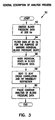
- FIG 3 there is shown an overview of the process 50 of arterial waveform analysis according to one example embodiment of the present invention.
- Figure 3 is representative of the process of arterial waveform analysis and also the underlying computer program which directs the execution of the process, through microprocessor 14, in system 10.
- Process 50 is carried out under program control by microprocessor 14 and/or its computer peripherals.
- the program can be stored in whole or in part in ROM 20 or in storage device 24 or RAM 22.
- the process 50 begins with digitizing an analog blood pressure waveform (52), preferably at 200 Hz, with a 16-bit resolution.
- waveforms are collected for a thirty (30) second duration. This data can be stored in RAM 22 or in storage device 24.
- oscillometric cuff pressure data input at port 31, just preceding the time of waveform acquisition in order to calibrate the waveform in terms of pressure in mm Hg.
- the data is filtered (54), preferably using an eight (8) pole, 25 Hz low pass Butterworth filter with an attenuation of 6.0206 dB at the comer frequency, for the purpose of marking individual beats.
- the initial filtering at 25 Hz provides sufficient smoothing of the blood pressure data to enable consistent marking for the upstroke (A), peak (B), and end diastolic point (D) for each beat. These locations are identified without the use of derivatives of the pressure data.
- the dicrotic notch (C) and the left and right scan points bracketing the notch (L-R), termed the near-notch region (NNR) derivatives of the pressure waveforms are utilized.
- Digital derivatives inherently amplify noise in the data and thus to minimize the noise in the derivatives of the blood pressure waveforms the porteon of the waveform between systole and end diastole for each beat is further filtered using an eight (8) pole, 15 Hz low pass Butterworth filter with an attenuation of 6.0206 dB at the comer frequency.
- the digitized waveform data is converted to pressure in mmHg for analysis using a two point calibration.
- the median systolic and median upstroke values are used together with the systolic and diastolic measurements of blood pressure obtained from the oscillometric cuff pressure measurement unit 35 to calibrate the pressure data.
- the median mean waveform value and the median upstroke waveform value together with the mean pressure and diastolic pressure determined from the oscillometric cuff pressure measurement unit 35 could be utilized to calibrate the data.
- a beat to beat cross correlation is then performed using Pearson's cross-correlation to determine a dominant family of beats, and a heart rate variability restriction is applied (58) in order to select a group of blood pressure beats for further analysis, as described more fully below.
- a heart rate variability restriction is applied (58) in order to select a group of blood pressure beats for further analysis, as described more fully below.
- no less than five (5) and no more than ten (10) beats are selected.
- the exact number selected is not critical.
- the last step in the illustrated process is the analysis of the marked and selected beats (60) to determine the sought after parameters of cardiovascular profile using, for example, the modified Windkessel model.
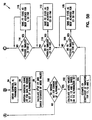
- the process 70 of step 60 begins with a check to determine if a predetermined number of beats has been analyzed successfully (72-74), and, if so, proceeds to calculate the weighted averages of variables (76), the generation of a representative ensemble beat for display (78), and output of the results from the analysis (80).
- the beat length of the ensemble beat is assigned to the median beat length of all of the beats included.
- the ensemble beat is generated by averaging the data values across beats point by point using the upstroke point of each beat as the fiduciary point.
- the reported C 1 and C 2 parameters are taken as the weighted average of measures across at least five (5) and at most ten (10) beats, according to one example embodiment
- the values are weighted by the ratio of the R 2 of the fit to the propagated error variance of fhe fit (model), as described more fully below.
- beat analysis is not complete, the process 70 obtains a beat for analysis (82). If there are no more diastolic data sets for the current beat, and the fit criteria are met for C 1 , C 2 and L (84-86), the running sums for all variables are calculated (88). If the fit criteria are not met, the process returns to step 72.
- Step 90 includes determining the near-notch region to be scanned for a beat and selecting the diastolic portion of a beat to analyze based on the current scan location and end diastolic mark.
- a parameter set is obtained (94).
- a Newton-Raphson curve fit of data is performed to obtain a final set of A i parameters from the empirical starting point (96), and a calculation of R 2 of fit and error estimates of model data is performed (98).
- Curve fitting for a given diastolic data set and model parameters are driven by minimization of the mean square error agreement between the modeled arterial waveform and the actual data.
- the coefficient of determination (R 2 value) is used to determine whether a particular fit meets a goodness of fit standard, taken in this example embodiment as an R 2 greater than or equal to 0.975, as more fully described below.
- step 92 If the fit criteria are not met (100), the process returns to step 92 and a different set of starting empirical A i parameters are obtained and the waveform re-fitted; if the criteria are met, the process proceeds to calculation of model values C 1 , C 2 and L based on the this A i parameter set (102).
- An estimate of the coefficient of variation (CV e propogated error of value unadjusted for SVR or pressure error, divided by the value) is then calculated (104) for C 1 , C 2 and L. If the fit produced the smallest CV e for C 1 (108), it is saved (108), for example in RAM 22 or in the storage device 24. Similar checks and saves are done for C 2 and L(110-116), and the process returns to step 84.
- steps 90-116 are repeated.
- the particular fit (model) on a beat will be accepted to later contribute to the C 1 or C 2 value reported if it produces a minimization of the CV e for that measure as the dicrotic start region is scanned.
- the near notch region is a region of the arterial waveform just surrounding the notch. In the above-noted process, the starting point for the diastolic data set is taken from an initial point in that region, and then moved forward until all sets have been considered.
- each near-notch region identified by the scanning over a range of diastolic starting locations, produces independent values of C 1 , C 2 and L.
- the limits of the scan range or window are taken as the location of the first positive going zero crossing of the second derivative to the subsequent negative going zero crossing of the second derivative, surrounding the notch point.
- a maximum scan window is defined to handle the case where the second zero crossing does not occur, as described more fully below.
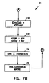
- process 70 applies a set of initial empirical model parameter values and a curve fitting algorithm such as the Newton-Raphson technique to the diastolic portion of the beat to obtain resulting curve fitting parameter values. If these parameter values meet the selection criteria for the regression between the model and data, the values are saved. If not, the next set of empirical model parameters are applied and the process repeated. This process is repeated for each scan location in a given beat so that at the end of beat analysis there is saved the fit state that results in the smallest estimated coefficient of variation, CV e , value for each of C 1 , C 2 and L independently.
- CV e the fit state that results in the smallest estimated coefficient of variation
- beat marking is to demarcate the individual beats contained in a collection of blood pressure waveform data. Marking the beats allows the individual beats to be examined separately and allows operations between beats like averaging all beats together or cross correlating individual beats together. As illustrated in Figure 4, the following locations are marked for each beat: the upstroke point (onset of systole) A, peak systole B, dicrotic notch region C, end diastole D and the marks bracketing the near-notch scan region L-R, as determined as set forth above and in more detail below.
- the upstroke mark (onset of systole) is taken as the prior minimum to the point at which the pressure change between data points five samples apart exceeds 10 mmHg.
- the peak systole mark B is taken as the peak or highest value for the beat.
- the dicrotic notch mark C is determined as outlined below.
- the diastolic mark D for the ith beat is initially taken as the upstroke mark of the ifh+1 beat. Subsequently, the distal portion of the diastolic range is scanned to identify the point at which the decay ceases to be monotonically decreasing by less than about .1%. This point is marked as the end of diastole, or mark D.
- the value .1% is not strictly critical, but is a good estimate of where to spot the end of the monotonic decrease. Other values around .1% are also acceptable to some degree.
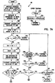
- Process 120 processes beats in steps 122-144.
- the first step (124) for each beat is to apply a low pass filter to the waveform data between the mark of systole and diastole for the current beat Because the derivative process amplifies noise, filtering is used to minimize this undesired effect.
- An eight (8) pole, 15 Hz lowpass Butterworth filter with 6.026db attenuation at the corner frequency is utilized to filter the region where derivatives are applied.
- the first derivative and second derivative of this waveform diastolic data set is calculated (126). The first derivative is used to determine if a notch minimum exists (128).
- notch location 132
- minimum location 134
- second derivateve is utilized to identify the notch location.
- the mid point between the peak of the second derivative and the subsequent minimum in a 20 point window from the peak is taken as the notch location (136).
- the near notch region is identified as in (138 -140) if no minimum existed or as in (142-144) if a minimum was identified. The only difference between the two is the point around which the zero crossings of the second derivatives are identified. In the first case if there is no second derivative zero crossing (140), the first local minimum in a twenty (20) window from the peak of the second derivative is found.
- Step 58 performs a beat to beat cross correlation using Pearson's cross-correlation to determine a dominant family of beats, and a heart rate variability restriction is applied in order to select a group of heart beats for further analysis.
- Beats are accepted that are within ⁇ 5% of the median beat length.
- the group with the greatest cross correlation coefficients with other beats meeting the criteria is taken as the dominant family of beats.
- the heart rate variability restriction limits the number of beats in the dominant family.
- three groupings are made based on the median beat length (MBL) of all the beats.
- Group 1 contains beats of length between 0.85*MBL and 0.95*MBL.
- Group 2 contains beats of length between 0.95*MBL and 1.05*MBL.
- Group 3 contains beats of length between 1.05*MBL and 1.15*MBL.
- the grouping with the most number of beats, most often the middle group, is used for subsequent ensembling and analysis.
- the example process of the invention utilizes a modified Newton-Raphson or equivalent curve fitting technique for determination of the model parameters for the above noted third-order equation.
- the process involves an iterative process to minimize the difference between the actual data and the model.
- the process utilizes at least one and at most five (5) sets of empirical 'A' parameters for each diastolic waveform data set analyzed within a beat. Multiple waveform data sets are generated by the process because a range of starting locations are used that cover the transition from the systolic phase of the pressure wave to the diastolic phase of the pressure wave, as noted above.
- the process (96) utilizes an iterative curve fitting routine in order to minimize the difference between the model and the actual acquired diastolic pressure data.
- the initial empirical 'A' parameters are copied at the beginning of the process, are modified in the curve fitting process, and result in a final set of 'A' parameter vaules.
- D is the difference vector between the actual data and the model fit for a given set of 'A' parameters.
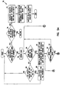
- Process 156 initializes variables, sets up error trapping and sets iErrorCode to efitNotFound.
- Process 158 copies initial 'A' parameter values from the current empirical values.
- Process 160 begins with the generation of the Jacobian matrix and a calculation of the initial mean square error of fit (errx) of the starting curve fit, and this value is then set equal to the current minimum (errmin) (162).
- a check is made to see if the current iteration (iter) is less than the iteration limit (iterlim) (166). If not less, the iteration limit (50) is reached and the process returns (202).
- step 170 iErrorCode is set to eFitFound to indicate that an acceptable fit was found. Errmin is set to errx and minIter is set to iter (172). The current 'A' parameter values are saved (174) and the covariance matrix is saved (176). The process continues at 192.
- step 192 errx is checked to see if it is greater than olden and if yes the rate of error increase is checked (194). If the rate of increase exceeds a desired threshold, the process is taken to be diverging and returns (202), otherwise the process continues with the next iteration (166).
- errx is not greater than olderr, the process proceeds to check if errx is less than a desired error limit (196). If so the process returns (202), otherwise errx is checked to see if it is less than or equal to a desired percentage or ratio of older and thus has met a convergence criteria (200). If the fit is not improving (200), the process returns (202). If the process does not currently meet the convergence criteria the process continues (166). Error trapping is handled by (206). If a numerical error occurs, iErrorCode is set to eFitNotFound (204) and the process returns (202).
- the curve fitting routine receives the data to be fit and an initial set of empirical values for the model parameters.
- the routine modifies the set of parameters by minimizing the mean square error between the actual data and the model fit, and produces an actual mean square error value that results from the fit.
- the objective is to achieve the best estimates for compliance by performing multiple analyses aimed at finding the best set of 'A' parameters to fit the waveform data.
- the goodness of a curve fit is assessed by the coefficient of determination and is calculated as follows: R 2 ⁇ 1- MSE / DiaVar where n initial is taken as the length of diastole from the left most scan point to the end of diastole. n is taken as the length of the current diastolic data set being fit. y is the actual data y is the mean of the data y and is the model fit to the data It is preferred in the example embodiment herein disclosed that criteria for an acceptable curve fit is a coefficient of determination value, R 2 , equal or greater than 0.975.
- the curve fitting is performed by a standard Newton-Raphson routine, which receives the data to be fit, and an initial 'A' parameter set, and returns either a set of final 'A' parameters and their estimated errors, or a return value indicating that a fit could not be found. If a fit is not found, or if the resulting parameters do not meet the standards for an acceptable fit, then the curve fitting is repeated using a different set of initial empirical parameters. It is assumed that the parameter set that failed may have fallen into a chi-squared local minimum, and that by starting the parameter search in a different area of parameter space, a lower minimum will be found that satisfies the curve fitting standards.
- the list of initial emgirical parameters that is used begins with five sets as set forth above that have been found empirically to provide success in almost all cases.
- One embodiment could add additional sets to be utilized to attempt to cover unique regions of parameter space and/or to add some randomly generated sets. If none of these starting sets find an accepted fit meeting all of the criteria, then the curve fitting is said to have failed, and the model cannot be applied to such a set of diastolic data.
- a successful curve fit to a diastolic data set establishes a set of model parameters which determines a C 1 and C 2 value for the beat It has already been described how data set boundaries are determined by waveform marking and how a single curve fit is obtained. Described below is how a subset of diastolic data within the data boundaries is chosen for the curve fitting and how compliance values are subsequently calculated.
- the modified Windkessel is designed to model diastole from beginning to end. Traditionally this means the start of the data set is the dicrotic notch point, and the end of the data set is the upstroke of the next beat Deviation from tradition for the end of the data set is described above. Described below is how selection of the starting point deviates from tradition.
- the impetus for finding anew way of selecting the starting point for curve fitting results from three observations when using the traditional method: first, many arterial waveforms simply lack a dicrotic notch, second, the timing of a notch minimum in the proximal aorta is not necessarily the same as the peripheral arteries, and third, a number of human subjects show excessive variation in repeated compliance measumments.
- any particular point is difficult to justify. If a point is chosen too early, then part of systole is included. If a point is chosen too late, then a crucial part of early diastole may be left out. In persons who show excessive variability on repeated measures, it is often the case that two measurements are very close to one another, while only a third is vastly different. This suggests that a consistent compliance value is being clouded by an occasional outlier.
- the starting point for the diastolic data set is allowed to vary over a range around which a notch would normally appear, termed the "near notch region.”
- a curve fit is performed and a compliance is obtained once for each starting point. By doing this it is found that many starting points produce roughly the same compliance value, while other starting points produce wildly different values. Again, although it seems as though a characteristic compliance value exists, it is difficult a priori to know which starting points will produce the best estimate of that value.
- the example embodiment of the present invention utilizes the theory that all the starting points are producing estimates for the same value, only with different levels of confidence. Every measurement has associated with it a level of confidence. To test the theory, an estimation of the precision for each compliance value is needed.
- the final weighted average is given by: where the summation is taken over all of the analyzed beats; f and final is the final value of the model parameter; r 2 / i is the coefficient of determination from the curve fitting process; each f i is chosen at the near notch range value which resulted in the smallest Var ( f i ); and the hat symbol ( ⁇ ) indicates the value is adjusted appropriately for R (e.g., RC 1 is divided by R).
- the example embodiment of the present invention uses the modified Windkessel model of the vasculature, and produces as output, the values C 1 , C 2 and L, with R being calculated from mean arterial pressure and cardiac output How mean arterial pressure and cardiac output are determined is not essential to the inventions claimed herein and are therefore not discussed further.
- method and apparatus for obtaining these meesurements are described in U.S. '177 and U.S. Patent No. 5,241,965, issued September 7,1993, and entitled “Method and Apparatus for Measuring Cardiac Output," the entire disclosure of which is herein incorporated by reference.
- the Total Vascular Impedance may also be calculated and output as data from device 10 as the impedance function evaluated at the frequency of the measured heart rate w.
- the above description is intended to be illustrative, and not restrictive. Many other embodiments will be apparent to those of skill in the art upon reviewing the above description. The scope of the invention should, therefore, be determined with reference to the appended claims, along with the full scope of equivalents to which such claims are entitled.
- the invention(s) is not limited to application to human patients and subjects, and may also be used for animals. As such, the invention is generally applicable for use on all mammals which exhibit blood pressure waveforms to which the present invention may be applied.
- the invention(s) is not restricted to any particular model of the human vasculature, but has applicability to any model, electrical, fluid, mechanical or otherwise, that involves analysis of the blood pressure waveform.
- both empirically and non-empirically determined starting values for the 'A' parameters can be used in order to find a fit that results in the desired minimization of error(s).
Landscapes
- Health & Medical Sciences (AREA)
- Life Sciences & Earth Sciences (AREA)
- Heart & Thoracic Surgery (AREA)
- General Health & Medical Sciences (AREA)
- Physics & Mathematics (AREA)
- Veterinary Medicine (AREA)
- Public Health (AREA)
- Animal Behavior & Ethology (AREA)
- Engineering & Computer Science (AREA)
- Biomedical Technology (AREA)
- Surgery (AREA)
- Medical Informatics (AREA)
- Molecular Biology (AREA)
- Cardiology (AREA)
- Acoustics & Sound (AREA)
- Pathology (AREA)
- Physiology (AREA)
- Biophysics (AREA)
- Vascular Medicine (AREA)
- Hematology (AREA)
- Measuring Pulse, Heart Rate, Blood Pressure Or Blood Flow (AREA)
- Investigating Or Analysing Biological Materials (AREA)
Claims (23)
- Vorrichtung zum Analysieren einer digitalisierten, arteriellen Blutdruckwellenform, umfassend einen Computer, der programmiert ist, um folgende Schritte auszuführen:a) Identifizieren eines diastolischen Abschnitts der Wellenform;b) Einpassen eines mathematischen Kurvenmodells zu dem diastolischen Abschnitt der Wellenform, um einen ersten Satz von Kurveneinpassungsparametern zu bestimmen;c) Einpassen des mathematischen Modells zu dem diastolischen Abschnitt der Wellenform, um einen zweiten Satz von Kurveneinpassungsparametern zu bestimmen;d) Bestimmen eines ersten Modellparameter von einem elektrischen Analogmodell eines Gefäßsystems für jeden des ersten und zweiten Satzes von Kurveneinpassungsparametern;e) Bestimmen einer Abschätzung des Fehlers, welcher jedem der ersten Modellparametern zugeordnet ist;f) Auswahl desjenigen ersten Modellparameters mit dem Kleinsten ihm zugeordneten Fehler als dem überlegenen ersten Modelparameter.
- Vorrichtung nach Anspruch 1, bei der der Computer weiterhin programmiert ist, um die weiteren Schritte auszuführen:g) Bestimmen eines zweiten Modellparameters eines elektrischen Analogmodells des Gefäßsystems für jeden der ersten und zweiten Sätze von Kurveneinpassungsparametem;h) Bestimmen einer Abschätzung des Fehlers, welcher jedem der zweiten Modellparameter zugeordnet ist;i) Auswahl desjenigen zweiten Modellparameters als überlegen, welcher den kleinsten ihm zugeordneten Fehler aufweist; undj) Mitteilen der ersten und zweiten Modellparameter, welche als überlegen ausgewählt wurden, an einen Benutzer der Vorrichtung, wobei die dem Benutzer berichteten ersten und zweiten Modellparameter nicht notwendigerweise aus dem gleichen Satz von Kurveneinpassungsparametern abgeleitet sind.
- Vorrichtung nach Anspruch 2, worin das elektrische Analogmodell ein elektrisches Analogmodell von zweiter oder höherer Ordnung ist.
- Vorrichtung nach Anspruch 3, worin das elektrische Analogmodell ein modifiziertes Windkesselmodell ist.
- Vorrichtung nach Anspruch 1, bei der der Computer weiterhin programmiert ist, um die weiteren Schritte auszuführen:k) Wechseln des identifizierten diastolischen Abschnitts der Wellenform und wiederholen der Schritte b), c), d) und e).
- Vorrichtung nach Anspruch 5, bei der der Computer weiterhin programmiert ist, um die Schritte auszuführen:I) Bestimmen eines Fehlers, welcher jedem im Schritt e) bestimmten Modellparameter zugeordnet ist, um zu ermitteln, welcher im Schritt e) bestimmte Modellparameter den kleinsten, ihm zugeordneten Fehler aufweist.
- Vorrichtung nach Anspruch 6, bei der weiterhin das elektrische Analogmodell wenigstens zwei ihm zugeordnete Parameter aufweist, von denen jeder verschiedene Aspekte des Gefäßsystems darstellt, und worin der Computer programmiert ist, um die folgenden Schritte auszuführen:m) Für jeden der zwei oder mehr verschiedenen Modellparameter, Identifizieren, welcher der im Schritt g) bestimmten Modellparameter den kleinsten, ihm zugeordneten Fehler aufweist, und Zuweisen des identifizierten Modellparameters zu der verarbeiteten Wellenform, worin ein erster identifizierter Parameter von einem ersten diastolischen Datensatz der diastolischen Wellenform abgeleitet werden kann und ein zweiter identifizierter Parameter von einem anderen diastolischen Datensatz der diastolischen Wellenform abgeleitet werden kann.
- Vorrichtung nach Anspruch 1, in der der Computer weiterhin programmiert ist, um die weiteren Schritte auszuführen:n) Markieren eines Punktes, welcher repräsentativ für den Beginn der Diastole ist; undo) Markieren eines Punktes, welcher repräsentativ für das Ende der Diastole ist, wobei das Ende der Diastole bestimmt wird, indem derjenige Punkt geortet wird, wo die Wellenform aufhört monoton zu fallen.
- Vorrichtung nach Anspruch 8, worin der Punkt, an welcher die Wellenform aufhört, monoton zu fallen bestimmt wird, indem der Punkt gefunden wird, an dem die Wellenform sich weniger als um eine 0,1 Prozentrate verändert.
- Vorrichtung nach Anspruch 1, bei der der Computer weiterhin programmiert ist, um die weiteren Schritte auszuführen:p) Identifizieren einer Region der Wellenform um die dikrotische Kerbe;q) Markieren eines Punktes auf der Wellenform innerhalb der Region als den Beginn der Diastole; undr) Markieren eines Punktes, welcher repräsentativ für das Ende der Diastole ist.
- Vorrichtung nach Anspruch 10, bei der der Computer weiterhin programmiert ist, um die Schritte auszuführen:s) Markieren des Punktes, welcher repräsentativ für das Ende der Diastole ist, basierend darauf, dass der Fall der Wellenform monoton ist.
- Verfahren zur Computeranalyse von digitalisierten Blutdruckwellenformen, verwendend ein elektrisches Analogmodell des Gefäßsystems, umfassend Identifizieren eines überlegenen Modellparameters von mehr als einem Modellparameter, worin jeder Modellparameter zu dem Modell eingepasst wird, worin der überlegende Modellparameter bestimmt wird mit Bezug zu einer Abschätzung des jedem Parameter zugeordneten Fehler.
- Verfahren nach Anspruch 12, weiter beinhaltend die Schritte:a) Identifizieren eines diastolischen Abschnitts der Wellenform;b) Einpassen eines mathematischen Modells einer Kurve zu dem diastolischen Abschnitt der Wellenform, um einen ersten Satz von Kurveneinpassungsparametern zu bestimmen;c) Einpassen des mathematischen Modells zu dem diastolischen Abschnitt der Wellenform, um einen zweiten Satz von Kurveneinpassungsparametern zu bestimmen;d) Bestimmen eines ersten Modellparameters von einem elektrischen Analogmodell eines Gefäßsystems für jeden der ersten und zweiten Sätze der Kurveneinpassungsparameter;e) Bestimmen einer Abschätzung des Fehlers, welcher jedem der ersten Modellparameter zugeordnet ist; undf) Auswahl desjenigen ersten Modellparameters als überlegen, welcher dem kleinsten ihm zugeordneten Fehler aufweist.
- Verfahren nach Anspruch 13, weiter beinhaltend die Schritte:g) Bestimmen eines zweiten Modellparameters eines elektrischen Analogmodells des Gefäßsystems für jeden der ersten und zweiten Sätze der Kurveneinpassungsparameter;h) Bestimmen einer Abschätzung des Fehlers, welcher jedem der zweiten Modellparametern zugeordnet ist;i) Auswählen desjenigen zweiten Modellparameters als überlegen, welcher den kleinsten ihm zugeordneten Fehler aufweist; undj) Berichten an einen Benutzer der Vorrichtung die ersten und zweiten Modellparameter, welche als überlegen ausgewählt wurden, wobei die berichteten ersten und zweiten Modellparameter nicht notwendigerweise von dem gleichen Satz von Kurveneinpassungsparametern abgeleitet werden.
- Verfahren nach Anspruch 14, worin das elektrische Analogmodell ein elektrisches Modell von zweiter oder höherer Ordnung ist.
- Verfahren nach Anspruch 15, worin das elektrische Analogmodell das modifizierte Windkesselmodell ist.
- Verfahren nach Anspruch 13, weiter beinhaltend die Schritte:k) Wechseln des identifizierten diastolischen Abschnitts der Wellenform und wiederholen der Schritte b), c), d) und e).
- Verfahren nach Anspruch 17, weiter beinhaltend die Schritte:l) Bestimmen eines Fehlers, welcher jeden der in Schritt e) bestimmten Modellparameter zugeordnet ist, um zu bestimmen, welcher der in Schritt e) bestimmten Modellparameter den kleinsten, ihm zugeordneten Fehler aufweist.
- Verfahren nach Anspruch 18, bei dem das elektrische Analogmodell weiterhin wenigstens zwei ihm zugeordnete Parameter aufweist, von denen jeder verschiedene Aspekte des Gefäßsystems darstellt, und beinhaltend den zusätzlichen Schritt:m) Für jeden der zwei oder mehr verschiedenen Modellparameter, Identifizieren, welcher der in Schritt g) bestimmten Modellparameter den kleinsten ihm zugeordneten Fehler aufweist und Zuweisen des identifizierten Modellparameters zu der verarbeiteten Wellenform, worin ein erster identifizierter Parameter von einem ersten diastolischen Datensatz der diastolischen Wellenform abgeleitet werden kann und ein zweiter identifizierter Parameter von einem anderen diastolischen Datensatz der diastolischen Wellenform abgeleitet werden kann.
- Verfahren nach Anspruch 13, weiter beinhaltend die Schritte:n) Markieren eines Punktes, welcher repräsentativ für den Beginn der Diastole ist; undo) Markieren eines Punktes, welcher repräsentativ für das Ende der Diastole ist, wobei das Ende der Diastole bestimmt wird, indem ein Punkt geortet wird, wo die Wellenform aufhört, monoton zu fallen.
- Verfahren nach Anspruch 20, beinhaltend den Schritt, den Punkt zu bestimmen, an dem die Wellenform aufhört monoton zu fallen indem der Punkt gefunden wird, an dem die Wellenform sich mit weniger als einer 0,1 %-Rate ändert.
- Verfahren nach Anspruch 21, weiter beinhaltend die Schritte:p) Identifizieren einer Region der Wellenform um dikrotische Kerbe;q) Markieren eines Punktes auf der Wellenform innerhalb dieser Region als den Beginn der Diastole; undr) Markieren eines Punktes, welcher repräsentativ für das Ende der Diastole ist.
- Verfahren nach Anspruch 22, weiter beinhaltend den Schritt:s) Markieren des Punktes, welcher repräsentativ für das Ende der Diastole ist, basierend darauf, dass der Fall der Wellenform monoton ist.
Applications Claiming Priority (5)
| Application Number | Priority Date | Filing Date | Title |
|---|---|---|---|
| US45018 | 1998-03-20 | ||
| US09/045,018 US6159166A (en) | 1998-03-20 | 1998-03-20 | Sensor and method for sensing arterial pulse pressure |
| US09/045,420 US6017313A (en) | 1998-03-20 | 1998-03-20 | Apparatus and method for blood pressure pulse waveform contour analysis |
| US45420 | 1998-03-20 | ||
| PCT/US1999/006057 WO1999048023A1 (en) | 1998-03-20 | 1999-03-19 | Apparatus and method for blood pressure pulse waveform contour analysis |
Publications (2)
| Publication Number | Publication Date |
|---|---|
| EP1062596A1 EP1062596A1 (de) | 2000-12-27 |
| EP1062596B1 true EP1062596B1 (de) | 2003-02-05 |
Family
ID=26722279
Family Applications (2)
| Application Number | Title | Priority Date | Filing Date |
|---|---|---|---|
| EP99912729A Expired - Lifetime EP1062596B1 (de) | 1998-03-20 | 1999-03-19 | Anlage und verfahren zur blutdruck-pulsform-konturanalyse |
| EP99912732A Withdrawn EP1063919A1 (de) | 1998-03-20 | 1999-03-19 | Sensor und verfahren zur messung des arteriellen blutdrucks |
Family Applications After (1)
| Application Number | Title | Priority Date | Filing Date |
|---|---|---|---|
| EP99912732A Withdrawn EP1063919A1 (de) | 1998-03-20 | 1999-03-19 | Sensor und verfahren zur messung des arteriellen blutdrucks |
Country Status (5)
| Country | Link |
|---|---|
| EP (2) | EP1062596B1 (de) |
| AT (1) | ATE232319T1 (de) |
| AU (2) | AU3104399A (de) |
| DE (1) | DE69905240T2 (de) |
| WO (2) | WO1999047044A1 (de) |
Cited By (1)
| Publication number | Priority date | Publication date | Assignee | Title |
|---|---|---|---|---|
| US7803122B2 (en) | 2004-05-17 | 2010-09-28 | Pulsion Medical Systems Ag | Device for determining the transition between systole and diastole |
Families Citing this family (4)
| Publication number | Priority date | Publication date | Assignee | Title |
|---|---|---|---|---|
| SI1481068T1 (sl) | 2002-02-26 | 2011-05-31 | Syngenta Ltd | Postopek za selektivno pripravo moških ali ženskih sterilnih rastlin |
| DE102004024334A1 (de) | 2004-05-17 | 2005-12-22 | Pulsion Medical Systems Ag | Vorrichtung zur Ermittlung eines hämodynamischen Parameters |
| DE102007001921B3 (de) | 2007-01-12 | 2008-08-28 | Enverdis Gmbh | Medizinischer Schallsensor sowie Diagnoseverfahren zur Diagnose von Herz- und/ oder Lungenerkrankungen |
| WO2011051819A1 (en) | 2009-10-29 | 2011-05-05 | Cnsystems Medizintechnik Ag | Digital control method for measuring blood pressure |
Family Cites Families (14)
| Publication number | Priority date | Publication date | Assignee | Title |
|---|---|---|---|---|
| US45018A (en) | 1864-11-15 | Improved device for operating center-boards | ||
| US45449A (en) | 1864-12-13 | William oallooit | ||
| US4409983A (en) * | 1981-08-20 | 1983-10-18 | Albert David E | Pulse measuring device |
| CH665112A5 (fr) * | 1985-10-11 | 1988-04-29 | Eric Furugard | Stethoscope acoustique et a filtre electrique. |
| US4989611A (en) * | 1988-08-19 | 1991-02-05 | Seismed Instruments, Inc. | Cardiac compression wave measuring system and method |
| CH681671A5 (de) * | 1990-03-12 | 1993-04-30 | Edwin Bollier | |
| US5241966A (en) | 1990-10-23 | 1993-09-07 | Hypertension Diagnostics, Inc. | Method and apparatus for measuring cardiac output |
| AU9119991A (en) * | 1990-11-27 | 1992-06-25 | Harry Herbert Peel Iii | Vital life sign detector |
| US5211177A (en) | 1990-12-28 | 1993-05-18 | Regents Of The University Of Minnesota | Vascular impedance measurement instrument |
| US5365937A (en) * | 1992-09-09 | 1994-11-22 | Mcg International, Inc. | Disposable sensing device with contaneous conformance |
| US5704362A (en) * | 1993-08-13 | 1998-01-06 | Johnson & Johnson Medical, Inc. | Method for oscillometric blood pressure determination employing curve fitting |
| WO1995006525A1 (en) * | 1993-08-30 | 1995-03-09 | Medacoustics, Inc. | Disposable acoustic pad sensors |
| US5535753A (en) * | 1994-10-04 | 1996-07-16 | Rutgers University | Apparatus and methods for the noninvasive measurement of cardiovascular system parameters |
| US5577508A (en) * | 1995-01-13 | 1996-11-26 | Johnson & Johnson Medical, Inc. | Determination of oscillometric blood pressure by linear approximation |
-
1999
- 1999-03-19 AT AT99912729T patent/ATE232319T1/de not_active IP Right Cessation
- 1999-03-19 DE DE69905240T patent/DE69905240T2/de not_active Expired - Fee Related
- 1999-03-19 AU AU31043/99A patent/AU3104399A/en not_active Abandoned
- 1999-03-19 WO PCT/US1999/006060 patent/WO1999047044A1/en not_active Ceased
- 1999-03-19 EP EP99912729A patent/EP1062596B1/de not_active Expired - Lifetime
- 1999-03-19 EP EP99912732A patent/EP1063919A1/de not_active Withdrawn
- 1999-03-19 AU AU31040/99A patent/AU3104099A/en not_active Abandoned
- 1999-03-19 WO PCT/US1999/006057 patent/WO1999048023A1/en not_active Ceased
Cited By (1)
| Publication number | Priority date | Publication date | Assignee | Title |
|---|---|---|---|---|
| US7803122B2 (en) | 2004-05-17 | 2010-09-28 | Pulsion Medical Systems Ag | Device for determining the transition between systole and diastole |
Also Published As
| Publication number | Publication date |
|---|---|
| EP1062596A1 (de) | 2000-12-27 |
| ATE232319T1 (de) | 2003-02-15 |
| EP1063919A1 (de) | 2001-01-03 |
| DE69905240T2 (de) | 2003-11-20 |
| WO1999048023A1 (en) | 1999-09-23 |
| HK1033377A1 (en) | 2001-08-24 |
| AU3104099A (en) | 1999-10-11 |
| WO1999047044A1 (en) | 1999-09-23 |
| DE69905240D1 (de) | 2003-03-13 |
| AU3104399A (en) | 1999-10-11 |
Similar Documents
| Publication | Publication Date | Title |
|---|---|---|
| US6017313A (en) | Apparatus and method for blood pressure pulse waveform contour analysis | |
| US5211177A (en) | Vascular impedance measurement instrument | |
| Millasseau et al. | Determination of age-related increases in large artery stiffness by digital pulse contour analysis | |
| JP3710823B2 (ja) | 心拍出量の測定のための改良された方法及び装置 | |
| CA2186686C (en) | Method and device for determining brachial arterial pressure wave on the basis of noninvasively measured finger blood pressure wave | |
| US20130102909A1 (en) | Method and apparatus for determining a central aortic pressure waveform | |
| JP2005087753A (ja) | 心拍開始点検出器 | |
| CN115251866A (zh) | 一种采用毫米波雷达的连续血压检测方法、检测系统及可穿戴装置 | |
| CN111248881B (zh) | 一种对血压进行预测的方法和装置 | |
| US20110270059A1 (en) | Signal processing for pulse oximetry | |
| GB2552455A (en) | Blood monitoring | |
| EP1062596B1 (de) | Anlage und verfahren zur blutdruck-pulsform-konturanalyse | |
| KR20120021098A (ko) | 맥파의 주파수 영역 분석을 이용한 혈관노화 평가방법 | |
| EP0957756B1 (de) | Nicht-invasive bestimmung der form von strömungsgeschwindigkeitssignalen in der aorta | |
| JP2016067490A (ja) | 末梢血管抵抗推定方法 | |
| HK1033377B (en) | Apparatus and method for blood pressure pulse waveform contour analysis | |
| Poliński et al. | Pulse transit time-fiducial points accuracy determination as examined by means of synthetic signals | |
| AU4932396A (en) | Non-invasive determination of aortic flow velocity waveforms | |
| HK1014351B (en) | Vascular impedance measurement instrument | |
| Voss et al. | Characterization of patients with dilated cardiomyopathy by finger arterial blood pressure waveform analysis |
Legal Events
| Date | Code | Title | Description |
|---|---|---|---|
| PUAI | Public reference made under article 153(3) epc to a published international application that has entered the european phase |
Free format text: ORIGINAL CODE: 0009012 |
|
| 17P | Request for examination filed |
Effective date: 20001020 |
|
| AK | Designated contracting states |
Kind code of ref document: A1 Designated state(s): AT BE CH CY DE DK ES FI FR GB GR IE IT LI LU MC NL PT SE |
|
| GRAH | Despatch of communication of intention to grant a patent |
Free format text: ORIGINAL CODE: EPIDOS IGRA |
|
| GRAH | Despatch of communication of intention to grant a patent |
Free format text: ORIGINAL CODE: EPIDOS IGRA |
|
| GRAA | (expected) grant |
Free format text: ORIGINAL CODE: 0009210 |
|
| AK | Designated contracting states |
Designated state(s): AT BE CH CY DE DK ES FI FR GB GR IE IT LI LU MC NL PT SE |
|
| PG25 | Lapsed in a contracting state [announced via postgrant information from national office to epo] |
Ref country code: NL Free format text: LAPSE BECAUSE OF FAILURE TO SUBMIT A TRANSLATION OF THE DESCRIPTION OR TO PAY THE FEE WITHIN THE PRESCRIBED TIME-LIMIT Effective date: 20030205 Ref country code: LI Free format text: LAPSE BECAUSE OF FAILURE TO SUBMIT A TRANSLATION OF THE DESCRIPTION OR TO PAY THE FEE WITHIN THE PRESCRIBED TIME-LIMIT Effective date: 20030205 Ref country code: IT Free format text: LAPSE BECAUSE OF FAILURE TO SUBMIT A TRANSLATION OF THE DESCRIPTION OR TO PAY THE FEE WITHIN THE PRESCRIBED TIME-LIMIT;WARNING: LAPSES OF ITALIAN PATENTS WITH EFFECTIVE DATE BEFORE 2007 MAY HAVE OCCURRED AT ANY TIME BEFORE 2007. THE CORRECT EFFECTIVE DATE MAY BE DIFFERENT FROM THE ONE RECORDED. Effective date: 20030205 Ref country code: GR Free format text: LAPSE BECAUSE OF FAILURE TO SUBMIT A TRANSLATION OF THE DESCRIPTION OR TO PAY THE FEE WITHIN THE PRESCRIBED TIME-LIMIT Effective date: 20030205 Ref country code: FI Free format text: LAPSE BECAUSE OF FAILURE TO SUBMIT A TRANSLATION OF THE DESCRIPTION OR TO PAY THE FEE WITHIN THE PRESCRIBED TIME-LIMIT Effective date: 20030205 Ref country code: CH Free format text: LAPSE BECAUSE OF FAILURE TO SUBMIT A TRANSLATION OF THE DESCRIPTION OR TO PAY THE FEE WITHIN THE PRESCRIBED TIME-LIMIT Effective date: 20030205 Ref country code: BE Free format text: LAPSE BECAUSE OF FAILURE TO SUBMIT A TRANSLATION OF THE DESCRIPTION OR TO PAY THE FEE WITHIN THE PRESCRIBED TIME-LIMIT Effective date: 20030205 Ref country code: AT Free format text: LAPSE BECAUSE OF FAILURE TO SUBMIT A TRANSLATION OF THE DESCRIPTION OR TO PAY THE FEE WITHIN THE PRESCRIBED TIME-LIMIT Effective date: 20030205 |
|
| REG | Reference to a national code |
Ref country code: GB Ref legal event code: FG4D |
|
| REG | Reference to a national code |
Ref country code: CH Ref legal event code: EP |
|
| REG | Reference to a national code |
Ref country code: IE Ref legal event code: FG4D |
|
| REF | Corresponds to: |
Ref document number: 69905240 Country of ref document: DE Date of ref document: 20030313 Kind code of ref document: P |
|
| PG25 | Lapsed in a contracting state [announced via postgrant information from national office to epo] |
Ref country code: LU Free format text: LAPSE BECAUSE OF NON-PAYMENT OF DUE FEES Effective date: 20030319 Ref country code: IE Free format text: LAPSE BECAUSE OF NON-PAYMENT OF DUE FEES Effective date: 20030319 Ref country code: CY Free format text: LAPSE BECAUSE OF FAILURE TO SUBMIT A TRANSLATION OF THE DESCRIPTION OR TO PAY THE FEE WITHIN THE PRESCRIBED TIME-LIMIT Effective date: 20030319 |
|
| PG25 | Lapsed in a contracting state [announced via postgrant information from national office to epo] |
Ref country code: MC Free format text: LAPSE BECAUSE OF NON-PAYMENT OF DUE FEES Effective date: 20030331 |
|
| PG25 | Lapsed in a contracting state [announced via postgrant information from national office to epo] |
Ref country code: SE Free format text: LAPSE BECAUSE OF FAILURE TO SUBMIT A TRANSLATION OF THE DESCRIPTION OR TO PAY THE FEE WITHIN THE PRESCRIBED TIME-LIMIT Effective date: 20030505 Ref country code: PT Free format text: LAPSE BECAUSE OF FAILURE TO SUBMIT A TRANSLATION OF THE DESCRIPTION OR TO PAY THE FEE WITHIN THE PRESCRIBED TIME-LIMIT Effective date: 20030505 Ref country code: DK Free format text: LAPSE BECAUSE OF FAILURE TO SUBMIT A TRANSLATION OF THE DESCRIPTION OR TO PAY THE FEE WITHIN THE PRESCRIBED TIME-LIMIT Effective date: 20030505 |
|
| NLV1 | Nl: lapsed or annulled due to failure to fulfill the requirements of art. 29p and 29m of the patents act | ||
| REG | Reference to a national code |
Ref country code: CH Ref legal event code: PL |
|
| ET | Fr: translation filed | ||
| PG25 | Lapsed in a contracting state [announced via postgrant information from national office to epo] |
Ref country code: ES Free format text: LAPSE BECAUSE OF FAILURE TO SUBMIT A TRANSLATION OF THE DESCRIPTION OR TO PAY THE FEE WITHIN THE PRESCRIBED TIME-LIMIT Effective date: 20030828 |
|
| PLBE | No opposition filed within time limit |
Free format text: ORIGINAL CODE: 0009261 |
|
| STAA | Information on the status of an ep patent application or granted ep patent |
Free format text: STATUS: NO OPPOSITION FILED WITHIN TIME LIMIT |
|
| REG | Reference to a national code |
Ref country code: IE Ref legal event code: MM4A |
|
| 26N | No opposition filed |
Effective date: 20031106 |
|
| PGFP | Annual fee paid to national office [announced via postgrant information from national office to epo] |
Ref country code: GB Payment date: 20050330 Year of fee payment: 7 |
|
| PGFP | Annual fee paid to national office [announced via postgrant information from national office to epo] |
Ref country code: FR Payment date: 20050331 Year of fee payment: 7 |
|
| PGFP | Annual fee paid to national office [announced via postgrant information from national office to epo] |
Ref country code: DE Payment date: 20050406 Year of fee payment: 7 |
|
| PG25 | Lapsed in a contracting state [announced via postgrant information from national office to epo] |
Ref country code: GB Free format text: LAPSE BECAUSE OF NON-PAYMENT OF DUE FEES Effective date: 20060319 |
|
| PG25 | Lapsed in a contracting state [announced via postgrant information from national office to epo] |
Ref country code: DE Free format text: LAPSE BECAUSE OF NON-PAYMENT OF DUE FEES Effective date: 20061003 |
|
| GBPC | Gb: european patent ceased through non-payment of renewal fee |
Effective date: 20060319 |
|
| REG | Reference to a national code |
Ref country code: FR Ref legal event code: ST Effective date: 20061130 |
|
| PG25 | Lapsed in a contracting state [announced via postgrant information from national office to epo] |
Ref country code: FR Free format text: LAPSE BECAUSE OF NON-PAYMENT OF DUE FEES Effective date: 20060331 |