EP1062741B1 - Systeme d'affectation des capacites utilisant des elements de reseau semi-autonomes pour mettre en oeuvre et controler un horaire d'emission - Google Patents
Systeme d'affectation des capacites utilisant des elements de reseau semi-autonomes pour mettre en oeuvre et controler un horaire d'emission Download PDFInfo
- Publication number
- EP1062741B1 EP1062741B1 EP99905453A EP99905453A EP1062741B1 EP 1062741 B1 EP1062741 B1 EP 1062741B1 EP 99905453 A EP99905453 A EP 99905453A EP 99905453 A EP99905453 A EP 99905453A EP 1062741 B1 EP1062741 B1 EP 1062741B1
- Authority
- EP
- European Patent Office
- Prior art keywords
- network
- transmission plan
- transmission
- implementation
- management component
- Prior art date
- Legal status (The legal status is an assumption and is not a legal conclusion. Google has not performed a legal analysis and makes no representation as to the accuracy of the status listed.)
- Expired - Lifetime
Links
- 230000005540 biological transmission Effects 0.000 title claims abstract description 250
- 230000006854 communication Effects 0.000 claims abstract description 79
- 238000004891 communication Methods 0.000 claims abstract description 77
- 238000000034 method Methods 0.000 claims description 60
- 230000008859 change Effects 0.000 claims description 14
- 238000013507 mapping Methods 0.000 claims description 8
- 238000012544 monitoring process Methods 0.000 claims description 6
- 238000012423 maintenance Methods 0.000 claims description 3
- 238000011156 evaluation Methods 0.000 claims description 2
- 238000007726 management method Methods 0.000 description 109
- 238000012550 audit Methods 0.000 description 34
- 230000008569 process Effects 0.000 description 31
- 230000004044 response Effects 0.000 description 30
- 230000001343 mnemonic effect Effects 0.000 description 11
- 238000013480 data collection Methods 0.000 description 9
- 239000000969 carrier Substances 0.000 description 6
- 229910052741 iridium Inorganic materials 0.000 description 5
- GKOZUEZYRPOHIO-UHFFFAOYSA-N iridium atom Chemical compound [Ir] GKOZUEZYRPOHIO-UHFFFAOYSA-N 0.000 description 5
- 230000001360 synchronised effect Effects 0.000 description 5
- 230000006870 function Effects 0.000 description 4
- 238000013468 resource allocation Methods 0.000 description 4
- 230000000694 effects Effects 0.000 description 3
- 230000007246 mechanism Effects 0.000 description 3
- 238000012986 modification Methods 0.000 description 3
- 230000004048 modification Effects 0.000 description 3
- 238000012545 processing Methods 0.000 description 3
- 230000011664 signaling Effects 0.000 description 3
- 230000000644 propagated effect Effects 0.000 description 2
- 238000001228 spectrum Methods 0.000 description 2
- 238000012546 transfer Methods 0.000 description 2
- 238000012384 transportation and delivery Methods 0.000 description 2
- 238000010200 validation analysis Methods 0.000 description 2
- 230000003190 augmentative effect Effects 0.000 description 1
- 230000000295 complement effect Effects 0.000 description 1
- 238000012790 confirmation Methods 0.000 description 1
- 238000013500 data storage Methods 0.000 description 1
- 238000010586 diagram Methods 0.000 description 1
- 230000003203 everyday effect Effects 0.000 description 1
- 230000007774 longterm Effects 0.000 description 1
- 238000010295 mobile communication Methods 0.000 description 1
- 238000011084 recovery Methods 0.000 description 1
- 230000008672 reprogramming Effects 0.000 description 1
- 238000007619 statistical method Methods 0.000 description 1
- 238000013519 translation Methods 0.000 description 1
- 230000000007 visual effect Effects 0.000 description 1
Images


Classifications
-
- H—ELECTRICITY
- H04—ELECTRIC COMMUNICATION TECHNIQUE
- H04W—WIRELESS COMMUNICATION NETWORKS
- H04W16/00—Network planning, e.g. coverage or traffic planning tools; Network deployment, e.g. resource partitioning or cells structures
- H04W16/18—Network planning tools
-
- H—ELECTRICITY
- H04—ELECTRIC COMMUNICATION TECHNIQUE
- H04L—TRANSMISSION OF DIGITAL INFORMATION, e.g. TELEGRAPHIC COMMUNICATION
- H04L41/00—Arrangements for maintenance, administration or management of data switching networks, e.g. of packet switching networks
- H04L41/08—Configuration management of networks or network elements
- H04L41/0896—Bandwidth or capacity management, i.e. automatically increasing or decreasing capacities
-
- H—ELECTRICITY
- H04—ELECTRIC COMMUNICATION TECHNIQUE
- H04L—TRANSMISSION OF DIGITAL INFORMATION, e.g. TELEGRAPHIC COMMUNICATION
- H04L41/00—Arrangements for maintenance, administration or management of data switching networks, e.g. of packet switching networks
- H04L41/22—Arrangements for maintenance, administration or management of data switching networks, e.g. of packet switching networks comprising specially adapted graphical user interfaces [GUI]
-
- H—ELECTRICITY
- H04—ELECTRIC COMMUNICATION TECHNIQUE
- H04L—TRANSMISSION OF DIGITAL INFORMATION, e.g. TELEGRAPHIC COMMUNICATION
- H04L41/00—Arrangements for maintenance, administration or management of data switching networks, e.g. of packet switching networks
- H04L41/14—Network analysis or design
- H04L41/142—Network analysis or design using statistical or mathematical methods
-
- H—ELECTRICITY
- H04—ELECTRIC COMMUNICATION TECHNIQUE
- H04L—TRANSMISSION OF DIGITAL INFORMATION, e.g. TELEGRAPHIC COMMUNICATION
- H04L43/00—Arrangements for monitoring or testing data switching networks
- H04L43/08—Monitoring or testing based on specific metrics, e.g. QoS, energy consumption or environmental parameters
- H04L43/0876—Network utilisation, e.g. volume of load or congestion level
- H04L43/0894—Packet rate
Definitions
- This invention relates to communication methods and apparatus for providing network management, bandwidth and path control in a heterogeneous network that may be composed of multiple vendor equipment and transmission paths. More specifically, the communication system concerns semi-autonomous implementation components within a management hierarchy to globally manage multiple vendor elements while satisfying local network demands.
- Telecommunications services have, for many years, attempted to optimize or minimize bandwidth usage between network elements. Since the modem communications era, brought about by the theories of Shannon, telecommunications engineers have been keenly aware of the need to provide optimal, or at least good solutions, to bandwidth allocation problems in point-to-point and point-to-multipoint networks.
- time division multiple access provides a means for multiple stations to access time slots on satellite carriers and thereby "share” bandwidth resources.
- CDMA Code Division Multiple Access
- CDMA provides a means to use code division modulation techniques (time and frequency modulation) for multiple point access to a predetermined range of bandwidth and thereby "share” bandwidth space.
- frequency division multi-access provides a means to divide up and share a finite bandwidth resource.
- Canadian patent application CA-A-2216672 discloses a mobile satellite system including a network engineering/systems engineering (NE/SE) system.
- the NE/SE performs the process of producing frequency plans for the satellite system.
- the NE/SE instructs a Network Operations Centre (NOC) to implement required configuration changes.
- NOC Network Operations Centre
- a system for controlling a network of communication devices (44, 46, 48, 50, 51, 56, 57, 58), each device communicating in the network according to a transmission plan specified by a management component (MC) of the system, the system comprising: a management component that controls the transmission plan for all communications devices in the network; and one or more implementation components (IC) that control one or more communication devices in the network according to instructions from the management component each implementation component comprising: receiving means for receiving at least one transmission plan from the management component; and output means for outputting a command to a communication device controlled by the implementation component to implement said transmission plan instead of the transmission plan currently being utilized by that communication device, said system being characterised in that: said transmission plan contains a scheduled implementation time for modifying the transmission plan for one or more devices in the network; each implementation component further comprises a decoding means for decoding said scheduled implementation time for said transmission plan from the transmission plan received by the receiving means; and said implementation component implements said transmission plan at the specified implementation time.
- MC management component
- IC implementation components
- a method for controlling a network of communication devices each device communicating in the network according to a transmission plan specified by a management component of the system, the method comprising the steps of: receiving at least one transmission plan from the management component that is determined based on performance evaluation of an existing transmission plan; and outputting a command to a communication device controlled by an implementation component to implement said transmission plan instead of the transmission plan currently being utilized by that communication device, characterised in that: said method further comprises decoding a scheduled implementation time for said transmission plan from the received transmission plan the scheduled implementation time being for modifying the transmission plan for one or more devices in the network; and implementing the transmission plan at the implementation time specified.
- the methods and apparatus disclosed herein may assign and re-assign available transmission resources in point-to-point, multipoint and broadcast wireless networks. This may be accomplished on the basis of information capacity and connectivity requirements between transmitters and receivers of communications links at the time of assignment or re-assignment.
- the system may also provide a network administrator with novel tools and automated methods to define and implement network transmission plans and to modify allocation decisions as traffic requirements change.
- the system may provide the tools to efficiently allocate transmission resources. These tools help implement the communications links that form wireless networks. An optimum resource or a "good fit" allocation is achieved when network users have just enough information transmission capacity to perform their tasks. One way to accomplish optimal or good transmission resource allocations in a wireless network is to analyze network users' usage patterns and allocate capacity according to a time-varying schedule.
- a management component can determine a transmission plan schedule that efficiently allocates the satellite bandwidth available to the network based on historical usage patterns.
- the management component may automatically schedule and implement a transmission plan.
- the management component may update or modify the scheduled transmission plans to satisfy the new requirements.
- the system may automate implementation of transmission plans by reprogramming the system when predetermined parameters are reached.
- the management component may determine a transmission plan from a historical analysis of bandwidth requirements between stations. This transmission plan may be automatically deployed to the network. The management component can then monitor and analyze network allocation demands to determine a new transmission plan. The new transmission plan can then be automatically deployed in the network when predetermined parameters are reached, such as, average change in bandwidth, e.g. , bandwidth in use/bandwidth in the transmission plan, exceeds a predetermined amount or if a predetermined amount of time has transpired.
- the transmission plans may be propagated as generic network commands and translated into corresponding equipment parameters and associated control commands as required for reconfiguring network equipment elements.
- the system may generate and distribute equipment configurations to network elements to reprogram for synchronized execution at predetermined times.
- the system further controls and schedules bandwidth between network elements to consider other network factors such as economic constraints.
- each communications carrier should have just enough bandwidth and power necessary to meet the needs of its corresponding users.
- optimum resource allocation is the primary goal, sub-optimum allocation may be tolerated when economic constraints may limit transmission resources to finite amounts.
- a dynamic bandwidth requirement at a network station may require an increase in bandwidth allocation from the station, such as when the queuing depth reaches a predetermined amount at the station switch.
- the station may have additional capacity available on an available communication link, however, the incremental capacity of the link may far exceed the bandwidth required to reduce the depth of the communication queue.
- the financial cost of the incremental capacity may exceed the cost of waiting for network usage to decrease to reduce the depth of the queue.
- the system in this case, would allow the network to back up and flow control the user data before the system would allocate additional capacity.
- the system provides methods to use finite transmission resources by enabling power and bandwidth to be re-allocated as needed to meet changing communications requirements in satellite networks.
- the capabilities of the system are applicable to all wireless networks that can be modeled as a collection of transmitters, transmission resources, and receivers.
- the system provides a means to manage heterogeneous or multiple vendor network equipment over heterogeneous or multiple vendor transmission resources with multiple transmission paths.
- One such path may be via programmable C-, Ku-, or Ka- band satellite networks.
- Other paths may be via discrete carriers available on a preprogrammed networks such as the Inmarsat, Globalstar or Iridium satellite systems.
- Yet other paths may be via third party medium or broadband networks such as the envisioned Teledesic satellite network.
- Yet another path may be over a programmable or managed network such as the Intelsat global satellite system.
- the system provides a means to define and manage capacity between network elements where the network may be a combination of a discrete bandwidth allocation network managed by an external system, a semi-programmable medium or broadband network wherein a varying amount of bandwidth may be allocated from an externally managed resource and a fully-programmable network where the resource is managed by a network management component.
- the management system provides a nearly transparent means by which an operator, user or network element may place demands on the network and the management system may satisfy those demands based on a least cost algorithm, quality of service parameters and pre-defined or time-varying transmission plans.
- the management system described may configure the transmission elements (transmitters and receivers) in a wireless network to implement a specified allocation of transmission resources according to varying, scheduled or ad-hoc capacity requirements.
- the system maintains a schedule of transmission plan implementations and may automatically perform each implementation at a scheduled time.
- the semi-autonomous network management system essentially consists of two semi-autonomous components.
- the first component is the Implementation Component (IC) which executes at a site containing network transmission elements and the second is a Management Component (MC) which executes at a network management site.
- IC Implementation Component
- MC Management Component
- These components may be connected via a user datagram Internet protocol messaging format.
- the IC may be a stand-alone application program that controls one or more network elements.
- a network element may be the station or communication equipment physically controlled by an IC. Thus, it is usually the case that the network element is a stationary or mobile communications node at a single physical location.
- the IC may, however, remotely control a network element.
- the IC application may execute in a dedicated processing environment such as a PC executing UNIX or other suitable operating system such as Windows or DOS.
- the IC may also execute on an integrated or embedded processor such as a PC on a card environment with an application specific or real time operating system executing thereon.
- the IC is semi-autonomous, e.g. , it can translate allocation commands from a management component into executable commands for its associated network elements without having direct, full-time contact with the network management component.
- the IC may store pre-programmed parameters, transmission plans, or collection commands for automatic execution.
- the IC may map a network programming language command set or generic allocation command to a vendor specific command sequence.
- the IC may contact the management component to receive permission to access network bandwidth, to report the unavailability of network elements, or to request different allocation parameters if or when local demands exceed the IC's preprogrammed allocations.
- the IC may provide independent control over network elements while maintaining or executing a management plan.
- transmission schedules may be loaded in advance of the implementation of the scheduled transmission plans. Then, at a predetermined time, the network can switch over to the new transmission plan to implement the optimal, or at least good solution, before more complicated dynamic bandwidth allocation algorithms would need to be employed.
- the system may also perform network usage analysis.
- Automated network usage analysis may require that the management component have access to traffic data collected for the network.
- the data may be collected automatically or manually by the management component or the implementation component may interact with the elements in the network to collect the usage data.
- the management component may use statistical methods to analyze the gathered network usage data to suggest or implement optimize transmission plans for efficient use of the available resources according to a schedule.
- bandwidth may be scheduled in accordance with a historical analysis of demands on the network. For example, it may be determined that Monday morning traffic is mostly outbound (i.e. , from a central earth station to a mobile station). On Fridays, however, most of the traffic is in the opposite direction (i.e. , from mobile stations back to the central earth station). In this instance, an assymetric channel may be opened for Monday traffic to provide higher outbound data and a slower speed return path. Then the opposite allocation may be established for Friday's traffic (e.g. , a high speed channel from a mobile station to the central station and a low speed acknowledgment channel from the central station back to the mobile station). This may provide an optimal, or at least a cost-effective solution for the capacity requirements at a particular time.
- the system may allocate capacity based on class of service parameters available, for example, through an Asynchronous Transfer Mode ("ATM") type packet format.
- ATM Asynchronous Transfer Mode
- a class of service may identify data packets with low priority for a particular application. In such a case, an expensive satellite carrier may not be necessary and a lower-cost transmission resource may be put online by the network to pass the required data packets.
- the present network can mix class of service bandwidth allocation methods with least cost routing decisions based on predetermined parameters programmed in the IC.
- the semi-autonomous nature of the network management components may use a datagram protocol for interprocess communication. More specifically, the network components may communicate through the use of the User Datagram Protocol ("UDP") over an internet protocol (“IP"). Communication between the management component and the IC may use a polled or interrupt methodology.
- UDP User Datagram Protocol
- IP internet protocol
- the management component contacts each of the ICs to pass UDP/IP messages or to receive Transmission Control Protocol/Internet Protocol ("TCP/IP") information from the particular IC.
- TCP/IP Transmission Control Protocol/Internet Protocol
- the IC may attempt to communicate with the management component.
- the interrupt mode may be used to reestablish contact with the MC if the IC loses synchronization with the network or to pass alarm or other local conditions happening at the IC that may not be detected by the management component.
- the IC may have a preassigned back-up channel or predetermined bandwidth allocation to communicate with the management component.
- the management component may be programmed to look for alarm conditions or communication attempts from the ICs when predetermined parameter thresholds are reached.
- the signaling control mechanize operates to ensure that each of the ICs receives the appropriate message(s) and that the transmission plan may be implemented according to the predetermined schedule.
- the signaling control mechanism between management component and implementation components may communicate by exchanging the following UDP/IP messages.
- a transmission control order specifies new transmission parameters for a transmitter or receiver.
- the TCO specifies the implementation time.
- the implementation time is the time at which elements should begin using the transmission parameters specified in the order.
- TCOs are generated by the system to implement a new transmission plan.
- the system sends TCOs to the ICs of transmitters and receivers that must change parameters to implement the new transmission plan.
- TCOs may be stored on a hard drive or other non-volatile storage so that they are preserved through IC restarts and at IC power failures.
- an IC may be down or may not be able to communicate with the managed equipment at the execution time of a TCO.
- the IC may implement the current transmission plan or may implement a default state when the IC reestablishes communication with the managed equipment.
- the IC may send an acknowledgment of a TCO when a TCO is received from the system. If any of the requested parameter changes cannot be implemented because the managed equipment or the configuration files do not support it, the IC notifies the management component of this in the acknowledgment.
- the IC may also check that the parameter values are valid for the managed network equipment. Parameter ranges are specified in the Equipment Controller configuration files in the IC, discussed further below.
- a confirmation message may not be necessary for reporting the successful implementation of a transmission control order. Because the majority of satellite networks implement single links to each remote site, if an IC is not able to implement a TCO, the IP connection to the system may be lost. The system management component may detect the problem from the lack of audit responses. If the system does not receive an audit response from an IC, the system may update the site status and alerts the management component alarm.
- An abort order may instruct the IC to cancel any pending TCO for the specified transmitter or receiver.
- the system may send abort orders when a pending implementation is canceled by the Administrator.
- the IC may send an acknowledgment when it receives an abort order.
- the IC may send an acknowledgment when it receives a TCO or abort order from the management component.
- An audit request may be periodically sent to an IC by the management component.
- the management component may send an audit request to check the status of a transmitter or receiver.
- One audit request may be sent for each transmitter and receiver being managed by an IC.
- An audit response may be sent by an IC when an audit request is received from the management component.
- the audit response may contain the current parameter values for the transmitter or receiver specified in the audit request.
- An audit response may be similar in structure to a TCO. It may include the hardware identification for a transmitter or receiver and a list of model parameters and their current values as reported by the physical hardware.
- the receive frequency model parameter may be a special case: the frequency reported by the demodulator may not match the commanded receive frequency. Sources of frequency error throughout a wireless carrier transmission process may result in an offset between the expected and actual receive frequencies. Many demodulators are designed to accommodate this frequency offset by searching for the transmitted carrier in a neighborhood around the commanded receive frequency. However, the system may also account for this receive frequency offset when determining whether the physical hardware is using the same parameters as in the most recently implemented TCO.
- the management component may periodically request the current parameters from all transmitters and receivers.
- This network auditing function may perform the following functions:
- the management component may notify a Bandwidth Administrator.
- the management component operator interface may use an audible as well as visual alert to improve the chance that a Bandwidth Administrator will notice the difference and act to resolve it.
- Fig. 21 shows equipment controller IC (150).
- IC (150) may have a configuration database (152) which stores a configuration mapping for end-user receiver and transmitter equipment which is interfaced by, for example, serial devices (164, 166, 172, 174) and parallel devices (188, 190).
- the receiver/transmitter equipment may be from multiple vendors and thus the configuration database (152) maps commands from the management component (156) to a particular device.
- This feature of the IC may allow the use of a generic network control language in commands sent to IC (150) (discussed further below).
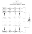
- the system is designed to manage all transmission equipment, regardless of manufacturer. To achieve this, the management component deals with model satellite transmitters and receivers as illustrated in Figure 6.
- the transmitter and receiver models have the parameters necessary to implement a wireless link. Only parameters that relate to the establishment of a wireless link need be included in the transmitter and receiver models.
- the management component may not require information about the physical equipment elements used to implement the communications links in the managed network. Therefore, the MC need not map the model parameters directly to commands for the physical hardware of the transmitters and receivers at a site.
- the IC may have information about the physical hardware at its site and may map the model parameters to the appropriate commands and responses.
- the IC may read information about the physical hardware from the configuration files. These files may specify the information required by the IC to monitor and control the managed equipment at a site.
- the IC configuration files may contain the information necessary to convert parameter changes for the model transmitters and receivers into commands to the physical hardware.
- the system is composed of two software components, the Management Component (“MC”) and the Implementation Component (“IC”) that work together to monitor and control the transmission elements in a wireless network.
- MC Management Component
- IC Implementation Component
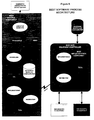
- the MC includes an operator interface for configuring, monitoring, and controlling the capacity allocation activity in a wireless network. It may be a Win32 application that runs on a Windows NT workstation which may be located at a network operations center (NOC). Configuration, monitoring, and control of the capacity allocation may be accomplished with the management component.
- the MC communicates with the other software component, the IC using the Internet Protocol (IP) family of network protocols as illustrated in Figures 4 and 5.
- IP Internet Protocol
- the IC is the application that may communicate with the physical hardware elements implementing the communications links in a wireless network.
- the IC may be a Win32 application that runs on a computer located at each site in the network.
- the IC may read a set of configuration files that describe the network equipment to be monitored and controlled. These configuration files may be text files and may be created and modified with a text editor program. In general, the configuration files are re-usable, that is the same configuration file may be used at multiple sites if the same network equipment is used at both sites.
- Figure 5 is a representation of the connectivity between the management component and the IC in a wireless network.
- the IP connections may be implemented on the satellite network, through the Internet, or through a private network.
- a second physical communication path between the MC and the ICs may be used to establish IP communications.
- ICs do not communicate with other ICs; however, communication links may be established between components to further communication with the MC.
- the management system is designed around several elements. These are the
- a transmitter is an equipment element that modulates an information signal so that it may access a wireless media.
- a receiver is an equipment element that demodulates a signal received from a wireless media to recover the information from the broadcast signal.
- a transmission element may be a transmitter or receiver in the network configuration.
- transmitters and receivers may be different and perform different functions, the management component may perform some operations in which transmitters and receivers are both treated the same way. For example, the MC may audit the status of all transmitters and receivers in the network. The management component may not distinguish between transmitters and receivers when performing this auditing operation.
- a wireless link may be created when an information signal is modulated by a transmitter and then demodulated by one or more receivers.
- a wireless communication network is a collection of communications links that enable information transfer among the sites in the network. Each link requires some of the transmission resources available to the wireless network. The allocation of the available transmission resources among the transmitters in a network is a transmission plan. These transmission plans may define the information capacity and connectivity requirements between the transmitters and receivers in the network.
- Transmitters Only transmitters may need to be specified in a transmission plan. Transmitters generate the signals that use transmission resources. The number of receivers demodulating a wireless signal does not affect the amount of transmission resources (bandwidth and power) used to implement the link.
- Implementation may be the process of configuring the transmitters and receivers in a wireless network to allocate the transmission resources as specified in a transmission plan.
- the management component may implement a transmission plan by sending orders to the ICs controlling the transmitters in the transmission plan and the receivers listening to those transmitters. These orders specify the transmission parameters for the transmitters and receivers and when they should be implemented.
- the IC send the equipment-specific commands that implement the transmission parameters at the specified time.
- the implementation schedule may be a list of all transmission plan implementations that may automatically be executed in the future.
- the schedule may be maintained by the MC application.
- An operator may add implementations to the schedule, remove implementations from the schedule, and move existing implementations to different times.
- An execution time consists of a transmission plan and the time at which the transmission will be implemented. The time may be a recurring time, for example 1200 UTC every day or 0600 UTC every Monday.
- the implementation schedule may be built from execution times.
- the information architecture of the system applies primarily to the structure of the database maintained by the Management Component and may define the structure of the messages exchanged between the management component and ICs.
- the information maintained by the management component may be stored in a relational database.
- the management component may require information about the wireless networks that it manages.
- a network may be viewed as being composed of sites, transmitters, and receivers. Information about these objects, e . g ., sites, transmitters and receivers, and the relationships among them may constitute a network configuration.
- a network may be a collection of sites that are linked by transmission resources. The following information may be specified for each network managed by the system:
- a site may be the physical location of an antenna in a wireless network.
- a site may have at least one transmitter or receiver. The system may require that the following information be provided for each site:
- the system may track the status of the transmitters in a wireless network. Possible status values for the tracked components may be:
- a receiver may comprise the equipment necessary to receive a carrier transmitted over a wireless resource and recover the digital data stream.
- the following information may be specified for each receiver:
- the system may maintain the following information for each receiver:
- a pool may be a collection of transmission resources available for use by the managed networks. Each transmission resource is a portion of transmission capacity (power and bandwidth). The following information may be required for each pool:
- the system may maintain the following information about each pool:
- a transmission resource may be a portion of transmission capacity (power and bandwidth).
- the system may require the following information about each transmission resource:
- the system may maintain the following information about each transmission resource:
- a transmission plan is an allocation of transmission resources to one or more carriers in a wireless network.
- the system specifies the following information about a transmission plan:
- the system may maintain the following information about a transmission plan:
- the system may manage sites with multiple transmitters and receivers. Therefore the system maintains a naming scheme for identifying a specific transmitter or receiver at a site.
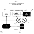
- Figure 9 may represents the flow of hardware identification information from the IC configuration files to the management component.
- the identification information may originate in the configuration files generated for a site in a network.
- the configuration files for a site may be read by the IC.
- FIG. 9 shows the information flow in the system.
- Each transmitter and receiver at a site may be designated by an equipment class.
- Each member of a class is assigned an instance number. Together, the equipment class and instance identify a unique transmitter or receiver at a site.
- a Bandwidth Administrator (902) may supply the hardware identification when configuring the transmitters and receivers of a site for bandwidth management.
- the flow of information shown in figure 9 simplifies network configuration maintenance and reduces the risk of problems due to inconsistent configuration information in the network.
- the circles with a slash (914, 916) illustrate that neither the Bandwidth Administrator (902) nor the management component (906) require access to the configuration files (910).
- the system software components may exchange information by sending and receiving messages using network or external connections.
- the management process may communicate with all of the IC processes. Each IC communicates only with the management component.
- the User Datagram Protocol (UDP) of the Internet Protocol (IP) suite may be used to transport the inter-process messages.
- the system may use the combination of IP address and UDP port to identify the ICs in the network. Site identification information may not be required in the message if the IP address and port are already available in the IP and UDP headers.
- the management and ICs may communicate using several types of messages. Although each type of message contains different information and fulfills a different purpose, the message types share some common characteristics as shown in Figure 15.
- Header fields may be present in system messages (1528). Typically, the order and format of the header fields are the same, regardless of message type.
- the format of a header field is simple: a string terminated by an ASCII linefeed (LF) character (1504, 1508 and 1510).
- the string can contain any printable ASCII character except LF.
- the management and ICs may communicate using the following message types:
- the mnemonic in parentheses after each message type is the identifier used in the first field (1502) of a system message (1526).
- the next field in a system message is a sequence number (1506).
- the management component maintains a sequence number for each piece of managed equipment (e.g. receiver or transmitter) in a network.
- the IC may use the sequence number from a request message in the response message.
- Sequence numbers may be used to match responses (ACK or ARSP) with requests (TCO, ABRT, or AREQ).
- ACK or ARSP requests
- TCO requests
- ABRT requests
- AREQ requests
- Figure 18 illustrates a transmission plan for allocating transmission media resources among transmitters in a network.
- a transmission media can be divided up into discrete segments (10).
- a network management plan can view discrete segments (10) of bandwidth as discrete transmission media sources (12).
- a transmission plan (16) may be used to map a network transmitter (18) through a link (14) to a predefined transmission media resource (12).
- transmission network transmitter (20) in particular transmitter (18) may be mapped through transmission plan (16) to two discrete segments (10) through link (14).
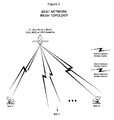
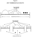
- the network media resource may be a star topology as shown in Fig. 1 or a mesh topology as shown in Fig. 2.
- Network transmission media resources may also be on separate networks.
- a first network transmission rsource may be capacity from the INMARSAT satellite network or through private networks on a C, KU, KA or L-Band.
- the network transmission resources may be further augmented by low earth orbiting satellites, medium earth orbiting satellites or geosynchronous satellites.
- Low earth orbiting satellites may be represented by the Iridium system employed by Iridium, Inc.
- Geosynchronous satellites may also provide additional transmission resources as represented by the Inmarsat or Intelsat satellite services.
- the management component or the ICs do not need to be in direct control of the bandwidth allocation to utilize transmission media sources.
- bandwidth allocation on the Iridium satellite system may operated independently of the management component and the ICs.
- the bandwidth allocation methodologies of, for example, the Iridium network may be employed to treat the resultant communication path as a transmission media resource under control of the management component.
- multiple carriers from a third-party system may be allocated in discrete predefined units, such as discrete segments (10), shown in Fig. 18, for utilization by the present invention as a media resource.
- Fig. 19 is a graphical depiction of network elements, ICs, a management component and a transmission plan.
- a central controller of the present invention may be represented by Management Component ("MC") (30).
- MC (30) is in communication with a plurality of ICs ("ICs") (32, 34, 38, 40) through links (31).
- ICs ICs
- Each IC may represent a particular site that is under network management control by the MC.
- Each IC may have network equipment (42) under its control.
- IC (40) has transmitter (44) under its control and BIC (38) has receivers (46, 48, 50, 51) and transmitters (56, 57) under its control.
- IC (36) has receiver (54) and transmitter (52) under its control.
- the present invention implements a transmission plan (43) through a mapping of network equipment (42) to transmission media resources (46).
- transmitter (44) has been allocated transmission media resource (45) for reception by receiver (48) as indicated through up link and down link mappings in transmission plan (43).
- This may represent a combined transmission media resource whose overall capacity is the entire discrete amount allocated at transmission media resource (45).
- a dynamic bandwidth requirement for a connection at a predefined class of service may be split into two discrete carriers.
- the discrete carriers may be represented by the two discrete media resources allocated at transmission media resource (45) to provide an overall throughput necessary to accommodate the predetermined capacity to support the class of service.
- the excess capacity may be used to provide the time recovered to reassemble the packets at receiver (48).
- This methodology is useful in the instance where, for example, a class of service from a particular end-user exceeds the network capacity to satisfy the demand on a single channel or contiguous media resource.
- the class of service requires a connection that exceeds the bit rate capacity of the modulator at a particular transmitter, but two modulators would supply ample bandwidth for the class of service.
- the IC or the management component could divide a packet data stream from the end-user device onto the two different modulators.
- multiple transmission media resources may be allocated to satisfy the overall class of service demand.
- a further representative example of a transmission plan employed herein is a broadcast from IC (38) through transmitter (56) which has been allocated transmission media resource (57).
- Transmission media resource (57) may be used for reception by both IC (34) and receiver (58) and IC (32) and receiver (60).
- This is an example of a point to multi-point broadcast.
- the point is represented by uplink transmitter (56) and the multi-points are represented by receivers (58) and (60).
- One representative application of such a plan is, for example, a broadcast message from transmitter (56) to two simultaneous sites represented by ICs (32) and (34).
- a transmission plan employed herein is transmitter (57), under control of IC (38), having an allocation of transmission media resource (61) for reception by receiver (54).
- IC (36) has transmitter (52) and transmission media resource (53) allocated for reception by receiver (50) at IC (38).
- This transmission plan may represent an asymmetric transmission, i . e ., the outbound channel from IC (38), represented at transmitter (57), has more media resources allocated which may indicate a higher bandwidth or higher data rate for reception by IC (36) through receiver (54) than the outbound channel from IC (36) through transmitter (52) through transmission media resource (53) for reception by receiver (50) to IC (38).
- Other representative permutations of the transmission plans employed herein are shown in Fig. 19 through the mapping transmission plan (43).
- Fig. 20 demonstrates the timing of how a representative transmission plan may be implemented by the management component.
- the transmission plan implementation begins with management component (100) having a predetermined command (102) to send to the network at a predetermined command time (110).
- Command(s) (102) is sent to IC (104) that must change transmission resource allocation at the implementation time.
- This command is stored in IC (104) and the time to implement the command is decoded by IC (104).
- IC (104) then sends a command acknowledgment (118) back to a management component (100).
- command (102) is loaded and awaits deployment at MC (100) at the predetermined command time (110).
- Command (102) is resent (122) if acknowledgment of receipt of command (118) is not received before a predetermined time.
- MC (100) may have a list of every IC (104) in the network that must change. This list may include the TCP/IP address for each IC (104) so MC (110) may send a UDP/IP message with a command (102) encoded therein.
- An acknowledgment deadline (134) is included that may be seconds before the implementation time for the new transmission plan. The acknowledgment deadline (134) may be the last time at which MC (106) can abort an implementation if each IC (104) does not acknowledge the commands.
- IC (104) may use a coordinated implementation to assure that no IC (104) is stranded when the transmission plan is implemented.
- MC (106) sends an abort message (126) to IC (108) that were sent command (102).
- IC (108) may send an abort acknowledgment (128).
- Abort command (126) is resent at step (130) if it is not acknowledged.
- the implementation time (136) defines a time at which the transmission plan is executed by IC (104). It is understood that at that point, all necessary ICs (104) have acknowledged command (118) and are counting down in a synchronized fashion to the predetermined implementation time (136).
- the command acknowledged may include an indication of the time at which an IC (104) received command (102) to verify that the implementation time (136) is synchronized among each IC (104).
- the ICs (104) implement the command(s) received from MC (100) at implementation time (136).
- a new transmission plan may be implemented by the network.
- the communication path between MC (30) and ICs (32, 34, 36, 38, 40) is independent of the transmission media resources.
- a transmission path (31) is generally over a TCP/IP network (e.g., the Internet), as widely known in use today.
- guard or maintenance channel which may be a point-to-multi-point transmission scheme from MC (30) to and from ICs (32, 34, 36, 38, 40) wherein an IC co-located with MC (30) assures that a network connection is present between ICs (32, 34, 36, 38, 40) and a MC allocated transmitter, such as transmitter (44).
- each IC (32, 34, 36, 38, 40) ready to implement the new transmission plan may have a receiver dedicated to monitor transmitter (44) to receive abort command (126) if each IC (32, 34, 36, 38, 40) does not acknowledge. This assures a fail safe or guard channel back-up plan to abort implementation of a new transmission plan if one or more IC (32, 34, 36, 38, 40) loses communication with the management component.
- Commands may enter the IC (150) from a plurality of sources, one of which may be directly from the MC.
- Node (158) may be a UNIX daemon or a Windows NTTM service which monitors a TCP/IP address.
- commands from MC (156) may enter IC (150) through a port (204).
- network commands may be mapped at step (158) in conjunction with configuration database information to output specific commands (178) to the network equipment. These commands may be put into a command queues (168, 180, 184) which is then directed through a scheduler process 162, 170 and 186.
- scheduled command implementation processes (162, 170, 186) may output commands to the appropriate receiver, transmitter or network device through a serial port (164, 166, 172, 174) or a parallel port (188, 190).
- Command queues (168, 180, 184) may be a polled or interrupt driven queue. That is, the schedule command implementation process (164) may periodically poll queues (168, 180, 184) to determine whether a command is present, and if so, pass the command on to the appropriate network device interfaced (e.g., serial device driver (164, 166)) or the command key may be a period.
- the command queue may alternatively be interrupt driven. That is, when a command enters queue (168, 180, 184), for example, command queue (168) may send an interrupt to the command implementation process for the command implementation process to service the command and then pass it to the appropriate network device at the appropriate serial port. It is understood that this process may be used for implementation processes (170, 186) as well.
- Command implementation processes (168, 170, 186) may be synchronized to network time (202) to execute commands at the appropriate time. That is, implementation of transmission plans may be synchronized with network time (202) to assure that all network devices reconfigure themselves simultaneously or near simultaneously.
- Implementation processes (168, 170, 186) may also have data from configuration database (152) to configure implementation process (168, 170, 186) for the particular end-user network device. This provides flexibility in implementation process (168, 170, 186). That is, the implementation may be written as a modular software program which may be modified by configuration database data (160) as implementation process (168, 170, 186) executes. Further to this concept is that MC (156) may address configuration database (152) via link (204) to change configuration database (152) to redefine the end-user equipment.
- IC (150) may communicate through module (158) via link (182) to send acknowledgments (200) back to the MC (156).
- Command acknowledgments (118) shown in Fig. 20 and order acknowledgements may also be used.
- Figs. 21-28 illustrate a step that may be used to confirm receipt of commands or to confirm receipt of an abort command.
- a TCP/IP address is provided for the IC in command (204) and then, within the UDP command, is a sub-address that may be decoded at (158) addressed to a particular end-user device.
- Fig. 22 shows a graphical block diagram of an audit control process by which data may be collected from network equipment.
- Implementation component (150) may have a configuration database (152) which controls the configurations of the IC in relation to the end-user network equipment.
- An audit request (252) may be received from the MC via port (254).
- Port (254) may be a user data packet via a TCP/IP network to a particular predetermined address at (256).
- an auto request command may be decoded to map an equipment name to hardware identification from those stored in configuration database (152).
- the process at (256) may also be used to map equipment attributes to data controls (290). These parameters may be passed to the reformat command process at (280) which is used to provide a formatted audit response (282) to the MC.
- the MC may establish an asynchronous data collection process (262, 264, 266) for the network equipment at a respective data port (268, 270, 272, 274, 276, 278) for the network equipment.
- Asynchronous data collection process (262, 264, 266) may be interrupt or poll driven.
- the end-user device may send out an unsolicited command via the respective device (e.g., device 268), to asynchronous data collection process (262, 264, 266).
- the interrupt then invokes the program to service the data condition (or possibly an alarm) from the network equipment.
- Asynchronous data collection process (262, 264, 266) then moves the data to the data control store block (258) where the alarm or data condition may be stored in the IC.
- the data control store block (258) may be a hard drive or other long term storage means available at the BIC.
- the data control store is a non-volatile data storage media and the asynchronous data collection process is a modular program because it is modified from data from configuration database (260) for the particular network device.
- This provides a flexible programming methodology for the asynchronous data collection process employed in the present invention.
- asynchronous data collection process (262) may periodically pole the end-user network device attached to, for example, port (268), to receive data or alarm conditions from the end-user device.
- the polling rate may be a parameter from the configuration database received via link (260).
- an audit request may be received via port (254) and decoded at (256) to output data from the data control store program (292).
- Data output from the data control store may be formatted at (280) from parameters past (290) from the audit request. This can provide an auto response (294) back to the BMC (282) in the appropriate and predetermined format.
- Fig. 23 shows a logic flow representation of a network audit from a MC (302).
- the MC (302) may establish an auto time for a network element, a transmitter or receiver (300). At the appropriate time, MC (302) may send out an audit request (306). It is understood that audit request (306) is directed to the network element and the particular IC controlling that element (308). The IC may then query the network element and send an audit reply (312) to the MC (310). Audit reply (312) is shown in time synchronization (316) after audit request (306).
- Initialization or configuration files may be used to implement the invention.
- a "command.ini” file may be used to provide user interface command definitions for all network management system equipment supported.
- the "command.ini” file specifies the menus associated with each control used on a user display.
- a “monitor.ini” file may be used to specify automatic monitoring functions performed by an implementation component.
- the “monitor.ini” file may act as the network management system data connection interface definition file.
- the "equipct1.ini” file may be used as the network management system controller initialization file. That is, the "equipct1.ini” file specifies some global parameters for the implementation component application. It may also specify the location of other configuration files if such files are not stored in a default or pre-determined location.
- the "event.ini” file may provide descriptions of network management system events.
- the "event.ini” file may specify textual responses (to user commands) displayed on a user interface and the asynchronous messages sent to either an event logger or other device.
- a "port.ini” file may be used as the network management system external connection definition file.
- the "port.ini” file may specify particular serial and parallel ports used by the implementation component.
- the "serial.ini" file may be used as the network management system serial command description file. This file may specify the command and response strings used to communicate with the manage equipment over a serial interface.
- the "panel.ini” file may be an the overall specification for the display controller presentation. This file ties together the display controls with specific input/output ports and describes the total graphic user interface for an equipment controller site.
- the "template.ini” file may be used as the network management system display template description file. This file specifies the graphic qualities of the controls used in the display controller presentation. Graphic qualities may include the position of the graphic control on a display, the type of display object, the name of any required bitmap graphic file, and a reference to any menu associated with the control
- the hardware identification field may contain information that identifies a specific transmitter or receiver at a site.
- the type of hardware may be one of the following classes:
- the ⁇ Class> portion of the hardware identification field may be one of the mnemonics shown in parentheses.
- Information fields (1524) and header fields (1528) may share some similarities. Each type of field is terminated with an ASCII linefeed (LF) character (1512, 1522).
- LF linefeed
- the primary difference between header fields (1528) and information fields (1524) is that the same header fields are found in all system messages while different messages can have different information fields.
- ⁇ mnemonic> is a mnemonic representing the field type
- ⁇ value> is a string representation of the field value.
- Both the mnemonic and the value of an information field may consist of printable ASCII characters.
- a transmission control order is sent from management component to an IC to request parameter changes for a transmitter or receiver controlled by the IC.
- a TCO has the following information fields:
- the execution time field specifies the time at which the TCO must be implemented.
- the TCO for each side of a communication link may have the same execution time to minimize the time the carrier is down during the change. Execution times may be given in UTC.
- Model parameters are specified as a parameter/value pair.
- An abort order may be sent to an IC to cancel any pending TCO for the specified hardware.
- An ABRT does not require any information fields.
- An acknowledgment informs the management component that the IC received the TCO or ABRT.
- An ACK is the response message for a TCO or ABRT.
- An IC receives a TCO or ABRT, it must send an acknowledgment to the management component. If the IC detects any problems with the TCO (configured hardware does not support a model parameter, hardware ID invalid, etc.) then the ACK will describe the problems.
- An ACK for an ABRT does not require this problem description.
- An ACK may have the following information fields:
- An ACK may have the same information fields as the TCO that is being acknowledged. However, model parameter fields are only present if the IC cannot fulfill that model parameter. For example, if the TCO contained an invalid receiver bit rate but a valid receiver frequency then the ACK would include an information field for the RXR model parameter but not for the RXF model parameter.
- An audit request is sent periodically by the MC for each transmitter and receiver in a satellite network. Each AREQ is sent to the BMF IC responsible for managing the specified transmitter or receiver. An AREQ does not require any information fields.
- An audit response is sent by an IC in response to an AREQ from the MC.
- An ARSP is the response message for an AREQ.
- An ARSP has the following information fields:
- the format of an ARSP may be almost identical to the format of a TCO: the message contains an information field for all of the model parameters pertaining to the specified piece of hardware. However, the values of the model parameters may be the actual settings of the hardware, not the desired settings.
- One purpose of the ARSP is to determine the state of the hardware in the network.
- a secondary purpose is to check for manually instituted changes to the configuration of the network hardware. For example, an operator at a remote site might manually change the receiver frequency using the front panel of the equipment.
- the management component periodically requests the current state of all managed equipment to check for parameter modifications not initiated by the management.
- the execution time for an audit response is the time at which the ARSP is generated.
- An ARSP may contain the model parameters for the type of equipment specified by the hardware identification.
- the value portion of the field may be "UNKNOWN".
- the IC may read its configuration files at startup and construct memory resident database tables and data 'objects' to facilitate rapid access to the configuration information stored in those files.
- the data read from the configuration files are the records that describe the equipment that the Management Console (MC) application will attempt to control by its commands to the Equipment Controller.
- the values of 'Attribute' and 'Value' are also represented as character strings and hence the entire dialog between the MC and IC is through text based messages.
- the IC configuration files identify one or more pieces of modeled equipment and a set of attributes that the modeled equipment can support. For example, the following section of an 'equipctl.ini' file describes an equipment element known as 'TRANSMITTER:Outbound'.
- the modeled attributes are identified by the 'EquipModemAttrs' entry and list the values TXF TXR MODT MODR ENCT ENCR DENC SCR PWR CXR as the legitimate attributes of the unit known as 'TRANSMITTER:Outbound'.
- This configuration entry may also associate other configuration entries with the equipment attributes that permit the equipment controller to set (modify) and get (recover) the attribute values from an actual piece of serially attached equipment.
- the entries in the list of 'EquipAttrSetCmds' refer to entries in the 'serial.ini' file that describe the actual command to be sent.
- the entries in the 'EquipAttrSetCmdPorts' and 'EquipAttrSetCmdAddrs' describe which serial port the attached equipment is connected to and the address of the attached equipment (in the case that multiple pieces of equipment are attached via the same serial port).
- the 'EquipAttrMonConns' entry refer to configuration entries in the 'monitor.ini' file that describe the mechanism by which the attribute is recovered from the attached equipment and the 'EquipAttrMonConnPorts' and 'EquipAttrMonConnAddrs' describe the serial ports and addresses used for data recovery.
- the IC is in not actually aware of the semantics of the data values it is 'setting' or 'getting' and the mapping between the equipment and equipment attributes that the MC believes it is controlling is completely defined by the equipment controller configuration files and not equipment controller software.
- the MC and IC communicate via the text format generally described above. All communication is initiated by the MC.
- Three request packets are currently defined: 1) a request to modify the attributes of a particular piece of equipment at a particular time in the future, 2) a request to cancel the request to modify the attributes of a particular piece of equipment, and 3) a request to return the current values of the attributes of a particular piece of equipment.
- Each request is normally responded to with a complementary message. In some cases, however, no response message purposely generated in order to communicate a negative response.
- TCO Transmission Change Order
- a response may be returned to the MC identifying the offending request data. For example, if a request contained an equipment identification that did not exactly match an entry in the 'equipctl.ini' file or if an attribute name did not exactly match one of the legitimate attributes named in the 'equipctl.ini' file, a response would be sent indicating why the TCO was invalid and implicitly indicating that the request would not be implemented. Further, if a legitimate attribute is named, but the equipment controller finds that either no serial command is referenced or that the referenced serial command is not configured, the IC may also send a similar response indicating why the request cannot be implemented. Validation of the parameter values may also be accomplished in a similar technique.
- ABRT Abort Message
- the IC may remove the outstanding command set to be issued to the specified equipment if any command is queued and may send an acknowledgment to the MC indicating it has done so. If, at the time of receipt, no command is outstanding, the IC may respond with a message indicating that no command was found.
- An Audit Message (AUDIT). The format of an AUDIT is as follows:
- the MC may request the current values of the equipment attributes by sending an AUDIT message to the IC.
- the message may contain specific attribute names or, in the absence of any attribute names, all attributes associated with the equipment are returned. Should the equipment or attributes identified not be defined in the IC configuration, the IC will send a message similar to the negative acknowledgment to a TCO indicating what particular field of the request message was found in error. If the AUDIT request message is found to be supported by the current IC configuration, the IC may will use the configuration entries identified by the 'equipctl.ini' file to recover the current values and will form a response message similar to the TCO message and send it to the MC.
- the response message format is as follows:
- Figure 13 depicts a flow chart of a transmission plan execution.
- the system may have an unscheduled transmission (1302).
- the transmission plan may be assigned an execution time (1304).
- the transmission plan may be propagated to the network to place the plan onto a pending status (1306).
- the transmission plan is ready for execution (1308).
- the plan began the start sequence.
- the MC confirms that all TCO's have been confirmed, e . g ., so that the MC does not issue an abort command, the transmission plan goes active (1312).
- the system then begins normal operation on the new transmission plan and the system begins collecting data again on link usage (1316).
- Special transmission plans e.g., transmission plans that are not recurring, are not re-scheduled (1318).
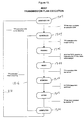
- FIG 14 depicts a bandwidth allocation request.
- This control loop may execute at the MC.
- the system may receive a request for bandwidth 1402 from the Bandwidth administrator or an IC.
- the request may be an unscheduled network event 1404.
- the request for bandwidth is decoded and scheduled for execution 1406.
- the execution schedule may be for immediate execution or for a scheduled deployment.
- the appropriate TCO may be sent from the MC to the appropriate IC to propagate the transmission plan and to put the plan into the ready state 1408.
- the transmission plan then waits for its execution time. When the transmission plan execution time arrives (1410) the MC confirms that the TCO's were confirmed by the ICs. If the TCO's were confirmed, the plan goes active (1412) at the predetermined time. the system has thereby fulfilled (1414) the bandwidth request.
- the IC may implement a control loop similar to that shown and described above.
- the IC may confirm that a channel is available within the present transmission plan 1406 and immediately execute the new transmission pan 1408, 1410 and 1412.
- the IC may then notify the MC 1402 of the unscheduled 1404 transmission plan.
- the MC may then proceed as described above to propagate and deploy the new plan.
- Figure 5 depicts the inter-process communication between the MC 502 and ICs (506) and 542.
- MC commands are sent via the UDP/IP link 504 from the control component 503 to the equipment control component 514.
- the equipment controller 514 then maps the generic network commands from the MC to specific commands (discussed above) for output (512) to the managed equipment (510).
- the equipment controller (514) may lose the command event (524).
- the IC may also denote the command event on the local display 530.
- the system may receive alarm and other network messages that may effect the network management display 518 via the TCP/IP connection 516.
- Equipment controller 514 may connect to the display controller 518 when the equipment controller 514 receives an alarm condition from the network equipment (510,520) via command links (512, 522).
- the event logger (534) may receive network audits and network events from the IC 506 equipment controller (514) via UDP/IP link 532. As provided above, each of the communication processes on Figure 5 may be interpret or poll driven.
- the IC may also denote the command event on the local display 530.
- the system may receive alarm and other network messages that may effect the network management display 518 via the TCP/IP connection (516).
- Equipment controller (514) may connect to the display controller (518) when the equipment controller 514 receives an alarm condition from the network equipment (510,520) via command links (512, 522).
- the event logger (534) may receive network audits and network events from the IC 506 equipment controller (514) via UDP/IP link (532). As provided above, each of the communication processes on Figure 5 may be interrupt or poll driven.
Landscapes
- Engineering & Computer Science (AREA)
- Computer Networks & Wireless Communication (AREA)
- Signal Processing (AREA)
- Human Computer Interaction (AREA)
- Mobile Radio Communication Systems (AREA)
- Communication Control (AREA)
- Management, Administration, Business Operations System, And Electronic Commerce (AREA)
- Data Exchanges In Wide-Area Networks (AREA)
Claims (19)
- Système pour commander un réseau de dispositifs de communication (44, 46, 48, 50, 51, 56, 57, 58), chaque dispositif communiquant dans le réseau en accord avec un plan de transmission définissant l'allocation de ressources de transmission entre lesdits dispositifs, spécifié par un composant de gestion (MC) du système, le système comprenant ;
un composant de gestion qui contrôle le plan de transmission pour tous les dispositifs de communication dans le réseau ; et
un ou plusieurs composants de mise en oeuvre (IC) qui commande(nt) un ou plusieurs dispositifs de communication dans le réseau en accord avec des instructions provenant du composant de gestion, chaque composant de mise en oeuvre comprenant :des moyens de réception pour recevoir au moins un plan de transmission provenant du composant de gestion ; ainsi quedes moyens de sortie pour produire en sortie un ordre vers un dispositif de communication commandé par le composant de mise en oeuvre pour mettre en oeuvre ledit plan de transmission à la place du plan de transmission actuellement en cours d'utilisation par ce dispositif de communication, ledit système étant caractérisé en ce que :ledit plan de transmission contient un horaire planifié de mise en oeuvre pour modifier le plan de transmission pour un ou plusieurs dispositifs dans le réseau ;chaque composant de mise en oeuvre comprend en outre un moyen de décodage pour décoder ledit horaire planifié de mise en oeuvre pour ledit plan de transmission à partir du plan de transmission reçu par les moyens de réception ; etledit composant de mise en oeuvre met en oeuvre ledit plan de transmission à l'horaire de mise en oeuvre spécifié - Système selon la revendication 1, dans lequel les dispositifs de communication comprennent des émetteurs et dans lequel le composant de gestion fait une correspondance entre des ressources de supports de transmission prédéterminées et des émetteurs.
- Système selon la revendication 2, dans lequel le plan de transmission modifie au moins une correspondance de ressource de supports de transmission prédéterminée spécifique et dans lequel les moyens de sortie du composant de mise en oeuvre transmettent l'ordre pour mettre en oeuvre le plan de transmission à au moins un émetteur et au moins un récepteur concernés par le changement dans la correspondance d'au moins ladite ressource de supports de transmission prédéterminée spécifique.
- Système selon l'une quelconque des revendications précédentes comprenant en outre un canal de maintenance qui permet des communications entre le composant de gestion et le ou les composants de mise en oeuvre pour la communication du plan de transmission entre le composant de gestion et les composants de mise en oeuvre.
- Système selon l'une quelconque des revendications précédentes dans lequel le réseau de dispositifs de communication comprend un réseau de communications par satellite et dans lequel les dispositifs de communication comprennent un équipement de réseau pour transmettre et recevoir des communications par satellites.
- Système selon l'une quelconque des revendications précédentes dans lequel le composant de gestion comprend :des moyens de détermination pour déterminer les dispositifs de communication dans le réseau concernés par un plan de transmission à mettre en oeuvre ; ainsi quedes moyens de création de message de plan de transmission pour créer un message contenant un plan de transmission à envoyer au composant de mise en oeuvre commandant les dispositifs de communication concernés par le plan de transmission.
- Système selon la revendication 6 dans lequel le composant de gestion comprend en outre :des moyens de transmission de plan pour transmettre le plan de transmission à tous les composants de mise en oeuvre commandant les dispositifs de communication concernés par le plan de transmission.
- Système selon la revendication 6 ou 7 dans lequel le composant de gestion comprend en outre des moyens de surveillance d'échéance d'accusé de réception pour l'établissement d'une échéance d'accusé de réception à la date de laquelle tous les composants de mise en oeuvre commandant les dispositifs de communication concernés par le plan de transmission doivent avoir envoyé un accusé de réception et pour la surveillance des accusés de réception en retour de l'ensemble de ces composants de mise en oeuvre.
- Système selon la revendication 8 dans lequel le composant de gestion comprend en outre des moyens de message d'arrêt pour envoyer un message d'arrêt à tous les composants de mise en oeuvre commandant les dispositifs de communication concernés par un plan de transmission si un accusé de réception n'est pas reçu de tous les composants de mise en oeuvre commandant les dispositifs de communication concernés par un plan de transmission avant l'échéance d'accusé de réception.
- Système selon la revendication 8 ou 9 dans lequel le message de plan de transmission comprend un numéro de séquence pour un dispositif de communication spécifique et dans lequel le numéro de séquence est utilisé pour déterminer si un accusé de réception est reçu de tous les composants de mise en oeuvre auxquels le plan de transmission a été envoyé.
- Système selon l'une quelconque des revendications précédentes dans lequel le réseau comprend une combinaison d'un ou plusieurs éléments parmi : un réseau d'attribution de largeur de bande discrète géré par un système externe, un réseau de support semi-programmable dans lequel une quantité variable de largeur de bande peut être allouée à partir d'une ressource gérée de façon externe et, un réseau entièrement programmable dans lequel les ressources sont gérées par un composant de gestion de réseau.
- Système selon l'une quelconque des revendications précédentes dans lequel le réseau de dispositifs de communication comprend un réseau TCP/IP et dans lequel les dispositifs de réseau de communication comprennent un équipement de réseau agencé pour transmettre et recevoir des communications en utilisant le protocole TCP/IP.
- Procédé pour contrôler un réseau de dispositifs de communication, chaque dispositif communiquant dans le réseau en accord avec un plan de transmission définissant l'allocation de ressources de transmission entre lesdits dispositifs, spécifié par un composant de gestion du système, le procédé comprenant les étapes consistant à :recevoir au moins un plan de transmission du composant de gestion qui est déterminé sur la base d'une évaluation de performance d'un plan de transmission existant ; etproduire en sortie un ordre vers un dispositif de communication commandé par un composant de mise en oeuvre pour mettre en oeuvre ledit plan de transmission à la place du plan de transmission actuellement en cours d'utilisation par ce dispositif de communication, caractérisé en ce que :ledit procédé comprend en outre le décodage d'un horaire de mise en oeuvre planifié pour ledit plan de transmission à partir du plan de transmission reçu, la mise en oeuvre planifiée étant l'horaire pour modifier le plan de transmission pour un ou plusieurs dispositifs dans le réseau ; etmettre en oeuvre le plan de transmission à l'horaire de mise en oeuvre spécifié.
- Procédé selon la revendication 13 dans lequel le plan de transmission modifie au moins une correspondance de ressource de supports de transmission prédéterminée spécifique et dans lequel un moyen de sortie du composant de mise en oeuvre transmet l'ordre pour mettre en oeuvre le plan de transmission à au moins un émetteur et à au moins un récepteur correspondant à ladite au moins ressource de supports de transmission prédéterminée spécifique, modifiée par le plan de transmission.
- Procédé selon la revendication 13 ou 14 comprenant en outre les étapes consistant à :déterminer les dispositifs de communication dans le réseau concernés par un plan de transmission à mettre en oeuvre ;créer un message contenant un plan de transmission à envoyer au composant de mise en oeuvre commandant les dispositifs de communication concernés par le plan de transmission, ettransmettre le plan de transmission aux composants de mise en oeuvre commandant les dispositifs de communication concernés par le plan de transmission.
- Procédé selon la revendication 15 comprenant en outre les étapes consistant à :établir une échéance d'accusé de réception à la date à laquelle tous les composants de mise en oeuvre commandant les dispositifs de communication concernés par le plan de transmission doivent avoir envoyé un accusé de réception ; et surveiller des accusés de réception en retour de tous ces composants de mise en oeuvre.
- Procédé selon la revendication 16 comprenant en outre l'étape consistant à envoyer un message d'arrêt à tous les composants de mise en oeuvre commandant les dispositifs de communication concernés par un plan de transmission si un accusé de réception n'est pas reçu en retour de tous les composants de mise en oeuvre commandant les dispositifs de communication concernés par un plan de transmission avant l'échéance d'accusé de réception.
- Procédé selon la revendication 16 ou 17 dans lequel le message de plan de transmission comprend un numéro de séquence pour un dispositif de communication spécifique et dans lequel le numéro de séquence est utilisé pour déterminer si un accusé de réception est reçu de tous les composants de mise en oeuvre commandant les dispositifs de communication auxquels le plan de transmission a été envoyé.
- Procédé selon l'une quelconque des revendications 13 à 18, comprenant en outre ; l'exécution d'une analyse historique de l'utilisation de réseau pour le réseau pendant une période de temps prédéterminée ;
la détermination d'une demande en réseau future probable à partir de l'analyse historique ; et
la génération d'un plan de transmission de manière à satisfaire sensiblement la demande en réseau future probable.
Applications Claiming Priority (3)
| Application Number | Priority Date | Filing Date | Title |
|---|---|---|---|
| US7233998P | 1998-01-23 | 1998-01-23 | |
| US72339P | 1998-01-23 | ||
| PCT/US1999/001317 WO1999038274A1 (fr) | 1998-01-23 | 1999-01-22 | Systeme d'affectation des capacites utilisant des elements de reseau semi-autonomes pour mettre en oeuvre et controler un horaire d'emission |
Publications (3)
| Publication Number | Publication Date |
|---|---|
| EP1062741A1 EP1062741A1 (fr) | 2000-12-27 |
| EP1062741A4 EP1062741A4 (fr) | 2001-10-04 |
| EP1062741B1 true EP1062741B1 (fr) | 2004-10-06 |
Family
ID=22106972
Family Applications (1)
| Application Number | Title | Priority Date | Filing Date |
|---|---|---|---|
| EP99905453A Expired - Lifetime EP1062741B1 (fr) | 1998-01-23 | 1999-01-22 | Systeme d'affectation des capacites utilisant des elements de reseau semi-autonomes pour mettre en oeuvre et controler un horaire d'emission |
Country Status (6)
| Country | Link |
|---|---|
| EP (1) | EP1062741B1 (fr) |
| AT (1) | ATE279048T1 (fr) |
| AU (1) | AU2560799A (fr) |
| CA (1) | CA2319345C (fr) |
| DE (1) | DE69920886T2 (fr) |
| WO (1) | WO1999038274A1 (fr) |
Families Citing this family (4)
| Publication number | Priority date | Publication date | Assignee | Title |
|---|---|---|---|---|
| WO2001043349A2 (fr) * | 1999-12-09 | 2001-06-14 | Siemens Aktiengesellschaft | Selection dynamique d'un procede d'acces a un moyen de transmission dans des reseaux de communication |
| US7379469B2 (en) | 2001-01-12 | 2008-05-27 | Broadcom Corporation | System and method for scheduling burst profile changes based on minislot count |
| WO2003019964A1 (fr) * | 2001-08-22 | 2003-03-06 | Nokia Corporation | Procede et appareil d'aide a la decision concernant l'ajout d'un noeud dans un reseau sans fil |
| US9166886B1 (en) | 2013-06-19 | 2015-10-20 | Google Inc. | Systems and methods for determining physical network topology |
Citations (3)
| Publication number | Priority date | Publication date | Assignee | Title |
|---|---|---|---|---|
| EP0791881A1 (fr) * | 1996-02-20 | 1997-08-27 | Compaq Computer Corporation | Gérant de configuration pour dispositifs de réseau et méthode associée pour fournir des informations de configuration |
| WO1997040449A1 (fr) * | 1996-04-22 | 1997-10-30 | Motorola Inc. | Procede et appareil de synchronisation de la mise en oeuvre d'informations de configuration dans un systeme de telecommunications |
| CA2216672A1 (fr) * | 1995-11-30 | 1997-12-25 | Amsc Subsidiary Corporation | Ingenerie de reseau/systeme d'ingenerie pour un systeme de communication satellite mobile |
Family Cites Families (5)
| Publication number | Priority date | Publication date | Assignee | Title |
|---|---|---|---|---|
| DE69130587T2 (de) * | 1990-05-10 | 1999-05-06 | Hewlett-Packard Co., Palo Alto, Calif. | System zum Integrieren von Anwenderprogrammen in eine heterogene Netzwerkumgebung |
| US5533023A (en) * | 1994-12-16 | 1996-07-02 | Stanford Telecommunications, Inc. | Practical means for dynamic allocation of individual demodulators to a multiplicity of received RF signals |
| US5592470A (en) * | 1994-12-21 | 1997-01-07 | At&T | Broadband wireless system and network architecture providing broadband/narrowband service with optimal static and dynamic bandwidth/channel allocation |
| US5689568A (en) * | 1995-06-29 | 1997-11-18 | Hughes Electronics | Medium access control for a mobile satellite system |
| SE508573C2 (sv) * | 1995-12-08 | 1998-10-19 | Ericsson Telefon Ab L M | Generisk informationsmodell för konfigurering, styrning och hantering av hjälpresurser i ett telekommunikationsnät |
-
1999
- 1999-01-22 AT AT99905453T patent/ATE279048T1/de not_active IP Right Cessation
- 1999-01-22 DE DE69920886T patent/DE69920886T2/de not_active Expired - Lifetime
- 1999-01-22 CA CA002319345A patent/CA2319345C/fr not_active Expired - Lifetime
- 1999-01-22 AU AU25607/99A patent/AU2560799A/en not_active Abandoned
- 1999-01-22 EP EP99905453A patent/EP1062741B1/fr not_active Expired - Lifetime
- 1999-01-22 WO PCT/US1999/001317 patent/WO1999038274A1/fr not_active Ceased
Patent Citations (3)
| Publication number | Priority date | Publication date | Assignee | Title |
|---|---|---|---|---|
| CA2216672A1 (fr) * | 1995-11-30 | 1997-12-25 | Amsc Subsidiary Corporation | Ingenerie de reseau/systeme d'ingenerie pour un systeme de communication satellite mobile |
| EP0791881A1 (fr) * | 1996-02-20 | 1997-08-27 | Compaq Computer Corporation | Gérant de configuration pour dispositifs de réseau et méthode associée pour fournir des informations de configuration |
| WO1997040449A1 (fr) * | 1996-04-22 | 1997-10-30 | Motorola Inc. | Procede et appareil de synchronisation de la mise en oeuvre d'informations de configuration dans un systeme de telecommunications |
Also Published As
| Publication number | Publication date |
|---|---|
| WO1999038274A9 (fr) | 1999-10-14 |
| CA2319345A1 (fr) | 1999-07-29 |
| EP1062741A1 (fr) | 2000-12-27 |
| DE69920886D1 (de) | 2004-11-11 |
| CA2319345C (fr) | 2009-09-08 |
| AU2560799A (en) | 1999-08-09 |
| ATE279048T1 (de) | 2004-10-15 |
| DE69920886T2 (de) | 2006-03-02 |
| EP1062741A4 (fr) | 2001-10-04 |
| WO1999038274A1 (fr) | 1999-07-29 |
Similar Documents
| Publication | Publication Date | Title |
|---|---|---|
| US6381250B1 (en) | Capacity allocation system using semi-autonomous network elements to implement and control a transmission schedule | |
| US6426959B1 (en) | System and method for facilitating component management in a multiple vendor satellite communications network | |
| US6255943B1 (en) | Method and apparatus for distributed object filtering | |
| US5713075A (en) | Network engineering/systems engineering system for mobile satellite communication system | |
| CN114598376B (zh) | 一种用于卫星网络管理和卫星测控的融合系统、其应用方法、及其部属方法 | |
| US20260100914A1 (en) | System and method for interference mitigation and congestion control through cross layer cognitive communications and intelligent routing | |
| US20060026301A1 (en) | SNMP proxy agent | |
| EP1976185B1 (fr) | Fonctionnement d'entités de réseau dans un système de communication comportant un réseau de gestion avec des niveaux d'agent et de gestion | |
| US12199738B2 (en) | Dynamic management of software-defined service chains for satellite communications | |
| US7325036B2 (en) | System and method for command transmission utilizing an email return path | |
| CN101507152A (zh) | 无线通信网络中可扩展元件管理系统 | |
| CN119172815B (zh) | 一种卫星网络确定性组网编排方法及系统 | |
| US6931441B1 (en) | Method and apparatus for managing a network using link state information | |
| EP1062741B1 (fr) | Systeme d'affectation des capacites utilisant des elements de reseau semi-autonomes pour mettre en oeuvre et controler un horaire d'emission | |
| WO2008090110A1 (fr) | Entités de réseau fonctionnelles dans un système de communications | |
| FR2752353A1 (fr) | Procede de connexion entre dispositifs de gestion de stations de base et centre de gestion de reseau | |
| Chitre et al. | VSAT networks: architectures, protocols, and management | |
| JP4673532B2 (ja) | マルチマネージャ環境における包括アライメントプロセス | |
| JP7724966B2 (ja) | 衛星通信のソフトウェア定義サービスチェーンの動的管理 | |
| US6097929A (en) | Method and system for monitoring and controlling a single channel per carrier satellite link between two remote earth stations | |
| Oliveira et al. | Distributed management based on mobile agents | |
| CN114584634A (zh) | 一种应用于运营管理的多层架构 | |
| Guillemin et al. | Reference architecture for slicing in LoRAWAN networks | |
| KATAOKA | Design of the Autonomous Satellite Link Operation Environment on the Internet | |
| WO1997036255A1 (fr) | Systeme et procede d'integration de donnees de planification et d'operations |
Legal Events
| Date | Code | Title | Description |
|---|---|---|---|
| PUAI | Public reference made under article 153(3) epc to a published international application that has entered the european phase |
Free format text: ORIGINAL CODE: 0009012 |
|
| 17P | Request for examination filed |
Effective date: 20000822 |
|
| AK | Designated contracting states |
Kind code of ref document: A1 Designated state(s): AT BE CH CY DE DK ES FI FR GB GR IE IT LI LU MC NL PT SE |
|
| A4 | Supplementary search report drawn up and despatched |
Effective date: 20010817 |
|
| AK | Designated contracting states |
Kind code of ref document: A4 Designated state(s): AT BE CH CY DE DK ES FI FR GB GR IE IT LI LU MC NL PT SE |
|
| 17Q | First examination report despatched |
Effective date: 20020429 |
|
| GRAP | Despatch of communication of intention to grant a patent |
Free format text: ORIGINAL CODE: EPIDOSNIGR1 |
|
| GRAS | Grant fee paid |
Free format text: ORIGINAL CODE: EPIDOSNIGR3 |
|
| GRAA | (expected) grant |
Free format text: ORIGINAL CODE: 0009210 |
|
| AK | Designated contracting states |
Kind code of ref document: B1 Designated state(s): AT BE CH CY DE DK ES FI FR GB GR IE IT LI LU MC NL PT SE |
|
| PG25 | Lapsed in a contracting state [announced via postgrant information from national office to epo] |
Ref country code: NL Free format text: LAPSE BECAUSE OF FAILURE TO SUBMIT A TRANSLATION OF THE DESCRIPTION OR TO PAY THE FEE WITHIN THE PRESCRIBED TIME-LIMIT Effective date: 20041006 Ref country code: LI Free format text: LAPSE BECAUSE OF FAILURE TO SUBMIT A TRANSLATION OF THE DESCRIPTION OR TO PAY THE FEE WITHIN THE PRESCRIBED TIME-LIMIT Effective date: 20041006 Ref country code: IT Free format text: LAPSE BECAUSE OF FAILURE TO SUBMIT A TRANSLATION OF THE DESCRIPTION OR TO PAY THE FEE WITHIN THE PRESCRIBED TIME-LIMIT;WARNING: LAPSES OF ITALIAN PATENTS WITH EFFECTIVE DATE BEFORE 2007 MAY HAVE OCCURRED AT ANY TIME BEFORE 2007. THE CORRECT EFFECTIVE DATE MAY BE DIFFERENT FROM THE ONE RECORDED. Effective date: 20041006 Ref country code: FI Free format text: LAPSE BECAUSE OF FAILURE TO SUBMIT A TRANSLATION OF THE DESCRIPTION OR TO PAY THE FEE WITHIN THE PRESCRIBED TIME-LIMIT Effective date: 20041006 Ref country code: CH Free format text: LAPSE BECAUSE OF FAILURE TO SUBMIT A TRANSLATION OF THE DESCRIPTION OR TO PAY THE FEE WITHIN THE PRESCRIBED TIME-LIMIT Effective date: 20041006 Ref country code: BE Free format text: LAPSE BECAUSE OF FAILURE TO SUBMIT A TRANSLATION OF THE DESCRIPTION OR TO PAY THE FEE WITHIN THE PRESCRIBED TIME-LIMIT Effective date: 20041006 Ref country code: AT Free format text: LAPSE BECAUSE OF FAILURE TO SUBMIT A TRANSLATION OF THE DESCRIPTION OR TO PAY THE FEE WITHIN THE PRESCRIBED TIME-LIMIT Effective date: 20041006 |
|
| REG | Reference to a national code |
Ref country code: GB Ref legal event code: FG4D |
|
| REG | Reference to a national code |
Ref country code: CH Ref legal event code: EP |
|
| REG | Reference to a national code |
Ref country code: IE Ref legal event code: FG4D |
|
| REF | Corresponds to: |
Ref document number: 69920886 Country of ref document: DE Date of ref document: 20041111 Kind code of ref document: P |
|
| PG25 | Lapsed in a contracting state [announced via postgrant information from national office to epo] |
Ref country code: SE Free format text: LAPSE BECAUSE OF FAILURE TO SUBMIT A TRANSLATION OF THE DESCRIPTION OR TO PAY THE FEE WITHIN THE PRESCRIBED TIME-LIMIT Effective date: 20050106 Ref country code: GR Free format text: LAPSE BECAUSE OF FAILURE TO SUBMIT A TRANSLATION OF THE DESCRIPTION OR TO PAY THE FEE WITHIN THE PRESCRIBED TIME-LIMIT Effective date: 20050106 Ref country code: DK Free format text: LAPSE BECAUSE OF FAILURE TO SUBMIT A TRANSLATION OF THE DESCRIPTION OR TO PAY THE FEE WITHIN THE PRESCRIBED TIME-LIMIT Effective date: 20050106 |
|
| PG25 | Lapsed in a contracting state [announced via postgrant information from national office to epo] |
Ref country code: ES Free format text: LAPSE BECAUSE OF FAILURE TO SUBMIT A TRANSLATION OF THE DESCRIPTION OR TO PAY THE FEE WITHIN THE PRESCRIBED TIME-LIMIT Effective date: 20050117 |
|
| PG25 | Lapsed in a contracting state [announced via postgrant information from national office to epo] |
Ref country code: LU Free format text: LAPSE BECAUSE OF NON-PAYMENT OF DUE FEES Effective date: 20050122 Ref country code: CY Free format text: LAPSE BECAUSE OF FAILURE TO SUBMIT A TRANSLATION OF THE DESCRIPTION OR TO PAY THE FEE WITHIN THE PRESCRIBED TIME-LIMIT Effective date: 20050122 |
|
| PG25 | Lapsed in a contracting state [announced via postgrant information from national office to epo] |
Ref country code: IE Free format text: LAPSE BECAUSE OF NON-PAYMENT OF DUE FEES Effective date: 20050124 |
|
| PG25 | Lapsed in a contracting state [announced via postgrant information from national office to epo] |
Ref country code: MC Free format text: LAPSE BECAUSE OF NON-PAYMENT OF DUE FEES Effective date: 20050131 |
|
| NLV1 | Nl: lapsed or annulled due to failure to fulfill the requirements of art. 29p and 29m of the patents act | ||
| REG | Reference to a national code |
Ref country code: CH Ref legal event code: PL |
|
| PLBE | No opposition filed within time limit |
Free format text: ORIGINAL CODE: 0009261 |
|
| STAA | Information on the status of an ep patent application or granted ep patent |
Free format text: STATUS: NO OPPOSITION FILED WITHIN TIME LIMIT |
|
| ET | Fr: translation filed | ||
| 26N | No opposition filed |
Effective date: 20050707 |
|
| REG | Reference to a national code |
Ref country code: IE Ref legal event code: MM4A |
|
| PG25 | Lapsed in a contracting state [announced via postgrant information from national office to epo] |
Ref country code: PT Free format text: LAPSE BECAUSE OF NON-PAYMENT OF DUE FEES Effective date: 20050306 |
|
| REG | Reference to a national code |
Ref country code: FR Ref legal event code: PLFP Year of fee payment: 17 |
|
| REG | Reference to a national code |
Ref country code: FR Ref legal event code: PLFP Year of fee payment: 18 |
|
| REG | Reference to a national code |
Ref country code: FR Ref legal event code: PLFP Year of fee payment: 19 |
|
| REG | Reference to a national code |
Ref country code: FR Ref legal event code: PLFP Year of fee payment: 20 |
|
| PGFP | Annual fee paid to national office [announced via postgrant information from national office to epo] |
Ref country code: GB Payment date: 20180129 Year of fee payment: 20 Ref country code: DE Payment date: 20180129 Year of fee payment: 20 |
|
| PGFP | Annual fee paid to national office [announced via postgrant information from national office to epo] |
Ref country code: FR Payment date: 20180125 Year of fee payment: 20 |
|
| REG | Reference to a national code |
Ref country code: DE Ref legal event code: R071 Ref document number: 69920886 Country of ref document: DE |
|
| REG | Reference to a national code |
Ref country code: GB Ref legal event code: PE20 Expiry date: 20190121 |
|
| PG25 | Lapsed in a contracting state [announced via postgrant information from national office to epo] |
Ref country code: GB Free format text: LAPSE BECAUSE OF EXPIRATION OF PROTECTION Effective date: 20190121 |