EP1062779B1 - Verfahren zur Absicherung von Datenvermittlungsnetzwerken - Google Patents
Verfahren zur Absicherung von Datenvermittlungsnetzwerken Download PDFInfo
- Publication number
- EP1062779B1 EP1062779B1 EP99906381A EP99906381A EP1062779B1 EP 1062779 B1 EP1062779 B1 EP 1062779B1 EP 99906381 A EP99906381 A EP 99906381A EP 99906381 A EP99906381 A EP 99906381A EP 1062779 B1 EP1062779 B1 EP 1062779B1
- Authority
- EP
- European Patent Office
- Prior art keywords
- network
- end node
- data
- net2
- net1
- Prior art date
- Legal status (The legal status is an assumption and is not a legal conclusion. Google has not performed a legal analysis and makes no representation as to the accuracy of the status listed.)
- Expired - Lifetime
Links
Images








Classifications
-
- H—ELECTRICITY
- H04—ELECTRIC COMMUNICATION TECHNIQUE
- H04L—TRANSMISSION OF DIGITAL INFORMATION, e.g. TELEGRAPHIC COMMUNICATION
- H04L63/00—Network architectures or network communication protocols for network security
- H04L63/14—Network architectures or network communication protocols for network security for detecting or protecting against malicious traffic
Definitions
- the present invention relates to techniques for providing security in data-communication networks. More specifically, this invention is directed to techniques that provide protected connectivity between different networks to prevent an intruder from exploiting weakness in network protocol(s).
- US Patent Number 5,021,949 relates to to a data communication system to link end hosts, supporting the SNA protocol stack, by means of a packet switched network, e.g., based on the IP protocol stack.
- US Patent Number 5,706,286 relates to to the interworking of different signalling protocols used by different telecommunication service providers, with particular reference to a SS7 gateway.
- International Patent Application Number WO 97/24842 relates to a method and system for providing a resilient interconnection between two frame relay networks and/or two end networks, suitable to provide end-to-end resiliency when the end-to-end interconnection is supported by different networks, i.e., to ensure end-to-end resiliency between frame relay networks interconnected by a self-healing network.
- FIG. 1 illustrates an example of a firewall (FW) used to connect an internal network NET2 with an external network NET1.
- external network NET1 is a WAN (Wide Area Network) such as the Internet
- NET2 is a LAN (Local Area Network), although the principles of the invention apply to networks generally.
- firewall FW A significant purpose of firewall FW is to block communications from NET1, which are suspected to be hostile. However, this is a patch to the problem and not a real solution, for the following reasons:
- the invention disclosed in the present application is a method for transmitting data in accordance with claim 1. It is also an object of the present invention a computer network in accordance with claim 43 and a machine readable medium in accordance with claim 71.
- network is used in the present invention to be a group of nodes (e.g., computers, storage devices, printers, etc.) connected together using physical and electronic interconnections such that each node is connected to at least one other node either directly or through intermediate links and/or devices, with all nodes complying with certain pre-agreed upon rules generally known as "protocols".
- a participant node in the network can transfer information to other nodes in the network by complying with network protocols.
- the connection between source and target generally passes though other participant nodes in the network which route the information to its destination.
- One aspect of the present invention involves isolating an internal network from an external network.
- the two networks should be disconnected.
- this transport should be as “dumb” and simple or “primitive” as possible. Consequently, the present invention introduces the concept of a "primitive network” which is a “barrier" between the internal network and the external network.
- a "primitive network” should be understood to mean a network consisting of front-end nodes and optionally, intermediate nodes.
- the front-end nodes can comprise one or more computers or dedicated hardware.
- the primitive network (along with its associated protocols, and physical and electronic connections) provide the mechanism for one front-end node to transfer information to any other front-end node (hereinafter, front end or FE).
- the optional intermediate nodes may be used to assist in the security or flow of information from one front end to another front end.
- the primitive network follows the rule that there is no electrical connection between the inside of a protected network and the outside at any given time, i.e. the inside and outside are electrically isolated from one another.
- the primitive network barrier is "breaking" all layers of the protocols on both sides (i.e., the internal and external networks) while allowing selective data carried by those protocols to pass.
- the primitive network does not support the full protocol stack used in the internal and eternal networks, but may support an entirely different protocol.
- FIG. 2 illustrates an internal network NET2 (e.g., a LAN) connected to an external network NET1 (e.g., the Internet) using the primitive network PN of the present invention.
- NET1 and NET2 may support various known and/or standardized communications protocols, an example of which is the TCP/IP family of protocols.
- TCP/IP Transmission Control Protocol
- NET1 and NET1 can operate with other types of protocols and that the protocols with which NET1 operates need not be the same as the protocols with which NET2 operates.
- NET1 is the Internet and NET2 is a LAN although it should be understood that other types of network configurations are common and expected.
- a third network a protective network, PN, in accordance with the invention is provided which has a front end FE1 connected to NET1 and another front end FE2 connected to NET2.
- the protective network PN typically employs a different communication protocol than that of either NET1 or NET2.
- the protocol used in PN can vary. For example, SCSI (Small Computer Systems Interface), SCSI-2, SCSI-3, parallel data port, serial data port USB, RS-232, ethernet (IEEE802.3), token ring (IEEE802.5), FDDI, ATM, fiber channels, etc., or proprietary protocols can be used. While it is preferable that protocol used in the PN should be as simple and "primitive" (uncomplicated) as possible, it is not necessary. For example, it is possible for the PN to use an SNA (System Network Architecture) protocol, which is a complex protocol.
- SNA System Network Architecture
- PN uses the SCSI protocol.
- FE1 and FE2 each comprise nodes on the primitive network as well as nodes on one or more adjacent networks; i.e., each is a gateway, sitting on 2 networks, and each can include commonly available computers or dedicated machines or hardware.
- a driver provides operative access to the primitive network. When communications are flowing from FE1 to FE2, one function of the driver in primitive network. When communications are flowing from FE1 to FE2, one function of the driver in the computer at FE1 is to strip the TCP/IP protocols from the data to be transmitted to NET2 and provide that data to the PN for transmission using protocol of the PN (e.g. the SCSI protocol).
- protocol of the PN e.g. the SCSI protocol
- One function of the driver in FE2 is to strip the SCSI protocol and provide the data for encapsulation using the (exemplary) TCP/IP protocol for transmission over NET2 to the destination. Since communication between NET1 and NET2 in FIG. 2 is intended to be bi-directional, the computer at FE2 also strips the TCP/IP protocols from the data to be transmitted to NET1 and insert the data into the envelopes of the SCSI protocol, and the computer at FE1 also uses its driver to strip the SCSI protocol and format the data into the TCP/IP protocol for transmission over NET1 to the destination.
- FIG. 3 illustrates a client-server application connection using the embodiment in FIG. 2
- FIG. 4 is an example of the communication flow for the client-server connection of FIG. 3
- OSI Open Systems Interconnection
- the WEB server WS while geographically residing at the merchant's offices, is actually connected to the Internet (NET1) (possibly through a firewall - not shown in the figure), and is accessible to the entire Internet population via the HTTP (Hyper Text Transfer Protocol) protocol over TCP/IP (the Internet backbone protocol).
- the merchant's catalog is stored on the WEB server, so the client can browse through the catalog and make his selection using the regular WEB based technologies: the client is shown several high level topics, and chooses one.
- the client's selection is encoded to an HTTP request by the browser (application level), and is transformed to TCP packet(s) using the TCP/IP stack at the client's computer.
- the packet moves its way down the protocol stack to the physical layer, and from there to some adjacent computer (possibly the client's Internet Service Provider (ISP)).
- ISP Internet Service Provider
- the packet goes up only to the routing layer (network layer) which brings it back down to the physical layer, only this time out through another interface to some other adjacent node.
- the packet continue to advance this way until reaching the WEB server node where the routing layer detects the packet has reached its destination and passes the packet to higher levels.
- the WEB server application receives the user's selection (at the application layer).
- the WEB server then fetches the appropriate catalog page, and builds an HTTP response containing the formatted item. It then sends the response to the client in the same manner described above, over the same TCP/IP link generated by the client's request.
- the client's browser strips the HTTP envelope (application layer) and displays the information on the client's screen.
- the above mechanism continues back and forth, until the client has made his decision to purchase a specific item.
- the decision about purchasing the specific item is transferred to the server in an HTTP request formatted as always, along with the client's identification details.
- the database containing the client accounts resides in the company's internal network (NET2) and is not accessible to the outside network via any of the TCP/IP based protocols, not even to the WEB server. This is done to protect this important database, and other internal resources, from being abused by a hacker hacking into the internal network by exploiting a weakness in one of the allowed protocols.
- the WEB server itself must be able to participate in TCP/IP sessions with unknown clients on the Internet. This is what makes the WEB server node a probable target for take-over attempts by hackers. Hence, even the WEB server should not be trusted in the internal network, and should not have inbound TCP/IP capabilities.
- the WEB server activates some application specific code that passes the data from the purchase order (at the application layer) to the front end's (FE1) driver.
- the front-end driver passes this information over the primitive network using the protocol(s) of the primitive network, if any.
- This data is picked up by the front end (FE2) of the internal network (first by its physical layer) and eventually passed via the driver to a specific application which verifies the data corresponds to a valid client and item information.
- the specific application contacts the internal database to charge the client's account, using standard protocols (e.g. SQLnet over TCP/IP). Packets flow in the internal network in the same manner described from the client to the WEB server.
- the specific application returns an acknowledgment that flows in the opposite direction all the way until received and displayed by the client's browser.
- a WEB server is placed in the internal network.
- the HTTP request information is passed through the primitive network, to a dedicated application that verifies its validity. Only specific requests from a predefined list are approved for internal processing. After a successful validation, the request information is passed to the internal WEB server which process the request as it normally does (and calls user written code that access the database if necessary).
- the output of the internal WEB server is then passed to the internal network front end and from there it is carried to the external network front end via the primitive network.
- the external WEB server returns the output to the client's browser, which was unaware of the entire process.
- the current invention involves limiting the risks taken when connecting the internal network outside to an external network, to specific, well-known application level risks.
- the primitive network or the internal network FE
- the primitive network can encrypt all inbound communications so that only authorized internal servers that posses the appropriate corresponding decryption key may use the incoming data.
- the primitive network or the internal FE
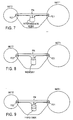
- FIG. 5 shows network NET1 connected to network NET2 over a primitive network.
- the primitive network shown in FIG. 5 is essentially a generic representation of several types of primitive networks which might be utilized to connect the two networks to provide security isolation as desired in accordance with the invention.
- the primitive network PN between NET1 and NET2 can be a simple wire connection over which the data flows once it has been removed from the TCP/IP envelopes which encapsulated it during its traversal of NET1 or NET2. Weaknesses in the TCP/IP protocol code that might ordinarily be exploitable by a hacker are not available once data (removed from its encapsulation) reaches the primitive network.
- FIG. 6 illustrates another example of a primitive network connecting NET1 and NET2.
- the primitive network is comprised of an RS232 link between the front ends of NET1 and NET2.
- the RS232 link has the ability, like a direct connection, to pass data that has been extracted from the TCP/IP encapsulation.
- the simplicity of the RS232 specification does not permit weaknesses in the TCP/IP protocol in NET1 that might be exploited by a hacker to propagate across the RS232 link into NET2.
- FIG. 7 is an exemplary embodiment in which the primitive network includes an intermediate node.
- This intermediate node can take several forms.
- the intermediate node is a memory medium.
- data coming from NET1 is written to the memory medium and then subsequently read by the front end connected to NET2.
- This approach permits not only the isolation provided by the primitive network PN, but isolation in time as well.
- the memory medium at the intermediate node of the primitive network takes the form of a magnetic storage medium, such as a hard drive
- the performance of the disk can be improved if writing to and reading from the disk occurs to/from a single sector.
- the latency associated with seeking a track and moving a read or write head over the track to which the data has been written is obviated. Rather, the read/write head(s) remains in one position and the reading and writing operations occur to a single track or sector consecutively.
- the read/write blocks can be adjusted to correspond to cache size so no reading and writing to the magnetic media need occur. This will increase the lifetime of the storage device, since it will decrease the movements of parts in the device.
- an electronic memory storage device can be used with no moving parts.
- the intermediate node of a primitive network can be a computer itself.
- the front end of NET1 loads the information from the front end into the intermediate node computer where it may be stored until it is sent to the front end of NET2 or retrieved by the front end of NET2 upon request.
- the intermediate node on the primitive network is shown generically as a switchable device which can be connected selectively to the front end of NET1 and to the front end of NET2. This keeps the two networks electronically disconnected at all times and ensures that the internal network FE is communicating with a trusted destination (the intermediate node) at all times without the interference of the external FE, an untrusted node.
- FIG. 11A illustrates a plurality of networks (NETA, NETB, NETC, NETD, NETE) connected using a primitive network PN which has a switchable intermediate node (e.g., a storage device).
- a switchable intermediate node e.g., a storage device.
- front end FEE of NETE is connected to the switchable intermediate node while being disconnected from all the remaining front ends (FEA, FEB, FEC, FED). Subsequently, the front end FEE of the NETE will disconnect from the switchable intermediate node and another of the front ends will connect to the switchable intermediate node while being disconnected from the other front ends.
- a single front end (of network NETA, NETB, NETC, NETD, NETE) at a time is connected to the switchable intermediate node.
- the switchable device is a disk drive.
- information can be transferred from the front end to the disk and from the disk to the front end.
- information stored on the disk can be read by the front end of NET2 and information from NET2 can be written to the disk. All transfers to and from disks can be done, preferably, using direct memory access (DMA).
- DMA direct memory access
- FIG. 12A shows the switchable device as two-switched storage devices.
- FE1 reads and writes information to storage device 1 while FE2 reads and writes information to storage device 2. Then the connection is toggled so that FE1 is connected to storage device 2 and FE2 is connected to storage device 1 so that each can read the other's (written) data and then write new data.
- FIG. 13 shows an extension of the concept shown in FIG. 12 with additional security features.
- the storage device shown in FIG. 13 operates under control of a controller; e.g., a hard disk with a hard disk controller.
- the hard disk controller has the ability to be selectively reset. When the disk controller is reset, it resets to a default state that has been predetermined either by the controller manufacturer or by an original equipment manufacturer (OEM) that incorporates the disk into the system.
- the reset position shown in FIG. 13 symbolically represents the fact that between the two states utilized to connect the disk to the front end of NET1 and to the front end of NET2, respectively, there is a resetting of the hard disk controller. This resetting does not affect any of the information stored in memory.
- the hard disk When the front end of NET1 writes information to the hard disk and receives information from the hard disk, the hard disk is connected to the front end of NET1 and disconnected from the front end of NET2. The hard disk connection is then switched to the front end of NET2 so the information can be transferred between the front end of NET2 and the hard disk.
- the controller is reset with each change of state of the switch. In this way, even if a hacker should achieve control of the controller of the hard drive, any settings that were deliberately corrupted by the hacker would be erased when the controller was reset.
- FIGS. 11-13 there is no instant of time during which there is a physical or electronic connection between NET1 and NET2.
- One way of demonstrating how this is accomplished is discussed hereinafter. However, it can be accomplished simply by ensuring that the connection to one side of the switch is broken before the connection to next side of the switch is made.
- the line illustrates a connection to a dual storage device (e.g., a hard disk) from both front ends
- the signal path between the front end of NET1 and the front end of NET2 is such that the signal path is never electrically continuous between the front end of NET1 and the front end of NET2.
- the data from the signal path from the front end of NET1 is written onto the hard disk of the primitive network and then, at a point displaced in time, read from the magnetic medium by the front end of network NET2. This displacement in time and the physical separation of the read/write heads from the magnetic medium (of the hard disk) ensures that no electrical connection is achieved, in the signal path between the front end of NET1 and the front end of NET2.
- the internal front end can inspect the information passed to it and decide whether to pass the information, as it is, modify it, or block it completely. If no clear decision can be made automatically, the information can be routed to a security officer console for a manual decision.
- Some of the checks that can be made at the internal front-end machine (or on other delegate nodes) include virus detection & digital signature authentication (both on inbound communications), and key word search (on outbound communications). Examples of modifications that can occur to data include the following: encryption and digital signing of outgoing transmissions, decryption of incoming transmissions, application level processing and format conversion.
- an important advantage of the described invention in one embodiment is the fact that all filtering is performed in the internal (secured) front end, and hence, cannot be overridden, even if the external front end is taken over by a hacker.
- all cryptographic keys are safely stored on the inside (secured) network and are not exposed to the outside. These keys cannot be retrieved even if a hacker took control over the external front end.
- FIG. 15 illustrates the concept that data filtering and modification can occur at both front ends FE1 and FE2.
- the incoming data can be tested for viruses and/or can be decrypted at FE2.
- data to be transferred outbound may be filtered or modified at the internal FE; e.g., encryption, key word detection, etc.
- both FE1 and FE2 may filter and modify the communication.
- Delegate nodes on behalf of the FE nodes may carry out the filtering (and modification) process.
- the delegate nodes reside on the same network as the FE (i.e., NET1 for FE1 and NET2 for FE2).
- FIG. 16 shows a network architecture in which two primitive networks (PN1, PN2) are utilized to achieve additional security between NET1 and NET2.
- PN1, PN2 primitive networks
- NET2 is assumed to be secure whereas NET1, typically the Internet, is definitely not secure.
- NET2 can be unsecure as well.
- One way of doing that is shown in the architecture of FIG. 16 .
- the front end of NET1 connects to an intermediate node over PN 1.
- the intermediate node then can perform all security processing on the information flows, including inspection and modifications.
- the information flow from the intermediate node can then pass to NET2 over PN2.
- the intermediate node that filters the data is protected from both networks and not even a hacker residing in the internal network (NET2) can override the security filtering performed on that node.
- FIG. 17 shows one way of achieving this.
- the RS232 link is partitioned so that data flows only in one direction. Specifically, the link in the opposite direction is disabled either by not equipping the RS232 connector with wiring or by throwing a switch.
- FIG. 18 A different implementation is shown in FIG. 18 with the storage device being, for example, a hard disk.
- the storage device being, for example, a hard disk.
- FIG. 18 one directional flow of information is achieved by imposing a write protect mode on the hard disk when the switch changes from connecting from one front end to connecting to the other front end.
- a write protect line is activated so that the information from the front end of NET2 cannot be written to the hard disk.
- Information can only be written to the hard disk from the front end of NET1 and thus information can flow only in the direction from NET1 to NET2 (in the example where NET2 is the internal network this configuration assures no leakage of information whatsoever from the (highly confidential) internal network).
- the default mode of the storage device is the read only mode and changes to a read/write mode only in response to a control signal.
- FIG. 19 illustrates the concept of assuring that no electrical connection (electrical isolation) is achieved in the signal path between the front end of NET1 and the front end of NET2 by checking for continuity (i.e. a short circuit) across the input and output of the switched device.
- FIG. 20 illustrates a sample implementation of checking for continuity across the switched path.
- a periodic wave e.g. a sine wave
- the other side of the bus connection determines whether or not the injected periodic wave is present on any of its signal wires. Presence of the wave indicates continuity across the switched path.
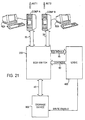
- FIG. 21 is a block diagram illustrating an implementation of the present invention, and includes two computers (COMP A and COMP B) acting as front ends for two networks, and a switchable storage device.
- Computer A is connected to a SCSI switch 200 via SCSI bus 20 and computer B is connected to switch 200 via SCSI bus 30.
- the bus signals from both SCSI buses 20 and 30 are provided as bus signals 50 to logic 400, which provides controls 60 to switch 200.
- Switch 200 is connected also to storage device 300 which can be, for example, a magnetic disk or an electronic memory device, via another SCSI bus 40.
- switch 200 is implemented as an analog switching device (described later) connecting storage device 300 to either SCSI bus 30 or SCSI bus 20.
- other implementations of switch 200 are possible.
- Signals to control the toggling of switch 200 originate in the driver that resides in the computer which is currently connected to the storage device 300 and can be in one preferred embodiment, an indication by each computer that it is finished accessing the disk. This indication is provided to logic 400 which issues controls 60 directing the switch 200 to toggle connection to the storage device from one SCSI bus to the other SCSI bus.
- the signal sent by a front end can be, in another embodiment, a command to write to a non-existent device.
- Logic 400 provides also a write enable signal to storage device 300 enabling the option of placing storage device 300 in either read/write mode or read-only mode.
- a user of the invention can select these modes.
- the mode of storage device 300 can be selected to be the read-only mode when connected to Computer A and to be the read/write mode whenever switch 200 connects Computer B thereto. Consequently, no data can flow from the network represented by Computer A to the network represented by Computer B through the primitive network.
- the default mode of storage device 300 is the read-only mode. This ensures the logic 400 has indeed allowed for the relevant FE to pass data.
- storage device 300 is, for example, set to read-only mode (unidirectional mode) when connected to computer A, no acknowledgement can be written to the storage device indicating that data has been successfully read and processed.
- FIGS. 22A and 22B are flow diagrams illustrating operation of a receiver driver and a sender driver in the read-only mode (unidirectional mode) for addressing this problem.
- a receiver (of the data) first determines whether the storage device 300 is attached and if not, waits until it is. When the storage device 300 is attached, the contents of the storage device are read and verified. Next, the content is processed (possibly by forwarding it to its ultimate destination for processing). If processing is successfully finished, a "toggle" signal is sent indicating that switch 200 should change connection.
- a delay of ⁇ seconds or fractions of a second is initiated (the storage device is held in one position), the internal context is reset and then the "toggle" signal is sent (after the delay). The delay is interpreted as a negative acknowledgement by the sender.
- a sender prepares a small chunk of information to be sent to the storage device and then queries whether or not the storage device 300 is attached. When the answer is NO, preparation of information continues until the storage device 300 is attached. When the storage device is attached (YES) a query is made as to whether time from a timer is ⁇ ⁇ (the delay in FIG. 22A ) and not the first time (the timer has been activated). If the response is NO, a block of preprocessed information is written to the storage device, the timer is started and the "toggle" signal is issued.
- the internal context is reset (meaning the next block that will be sent will represent the beginning of the transmission)
- a block of data is written to the storage device, the timer is restarted and the "toggle" signal initiated.
- the sender will determine that the timer time is greater that ⁇ which indicates that the information should be resent.
- Delay ⁇ should be chosen such to be much longer than a normal cycle time to avoid needless resets.
- FIG. 21A shows a variation of FIG. 21 where a signal to release the storage device 300 is sent by special command from FE1 and FE2 to the storage device 300 via the switch connections of switch 200 and SCSI bus 40.
- the storage device 300 then issues a control signal to logic 400 which issues controls 60 directing the switch 200 to toggle connection from one SCSI bus to the other SCSI bus.
- FIG. 21B shows still another variation of FIG. 21 where a signal to release the storage device 300 is sent from the front end directly to logic 400.
- Logic 400 then issues controls 60 directing the switch 200 to toggle connection from one SCSI bus to the other SCSI bus.
- FIG. 23 is a block diagram illustrating storage device 300 of FIG. 21 .
- Data is received from SCSI bus 40 by controller 310.
- a SCSI terminator 350 ensures proper termination of the SCSI bus.
- Controller 310 is also connected to microprocessor 320, which provides control, address and data signals to the controller 310.
- An auxiliary bus connects the microprocessor to CPLD 330 (Complex Programmable Logic Device) which provides control signals and DMA (Direct Memory Access) addresses to memory 340.
- CPLD 330 Computer Programmable Logic Device
- DMA Direct Memory Access
- the write enable signal from logic 400 which is used to place the memory 340 into the read/write mode or read-only mode, is provided to CPLD 330 and forms part of the control signals to memory 340.
- the default mode of memory 340 is the read-only mode.
- FIG. 24 is a block diagram illustrating logic 400 of FIG. 21 .
- CPLD Complex Programmable Logic Device
- CPLD Complex Programmable Logic Device
- FIG. 24 is a block diagram illustrating logic 400 of FIG. 21 .
- CPLD Complex Programmable Logic Device
- CPLD is used to drive components on a front panel (not shown); e.g. LEDs, as well as to provide control signals 60 and the write enable signal.
- CPLD is used also to detect the attempted connection to the non-existence device mentioned earlier.
- an analog preprocessing circuit 450 to provide the necessary digital signals from the raw bus signals received on the bus 50, continuity check circuit 410, injector generator 430 and clock 420 to synchronize continuity check circuit 410 and injector generator 430.
- a signal from injector generator 430 is provided with control signals 60.
- Continuity check circuit 410 and injector generator 430 (described in more detail later) are used to check for continuity of the connection as mentioned earlier.
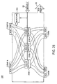
- FIG. 25 is an illustration of switch 200 of FIG. 21 .
- the switch 200 has two SCSI ports on one side (one labeled COMP A and the other labeled COMP B) and two SCSI ports on the other side (one labeled TERM and the other labeled DISK).
- the switch 200 can connect either COMP A to DISK and COMP B to TERM, or connect COMP A to TERM and COMP B to DISK. In either case, this is transparent to both SCSI buses.
- DISK is connected to a terminated SCSI storage device
- TERM is connected to a SCSI terminator.
- TERM can be connected to a second terminated SCSI storage device.
- each FE has a storage device attached to itself at all time, while still disconnecting the front ends.
- the signal provided from injector generator 430 is input to injectors 220, discussed more hereinafter, for injecting a signal to the lines from computer B.
- injectors 220 discussed more hereinafter, for injecting a signal to the lines from computer B.
- detectors shown in FIG. 26 and 27
- FIG. 25 shows injecting signals on the lines from computer B, this could be reversed and a signal could be injected to the lines from computer A with the detectors connected to the lines from computer B.
- FIG. 26 is a diagram showing an exemplary connection of the generator 430, clock 420, and injectors 220 and continuity check circuit 410, which are used in the continuity checking.
- the CLK signal from clock 420 is provided to both the injector generator circuit 430 and to the continuity check circuit 410.
- the CLK signal is input to jitter circuit 291 which keeps the injection generator synchronized and the output of jitter circuit 291 is provided to the base of NPN transistor 292 through a voltage divider since the based is connected to a node between serially connected resistors 293 and 295. This, in conjunction with the injectors, compensate for behavior changes of the transistors when the temperature varies.
- VCC is provided to another end of resistor 295 as well as to the collector of transistor 292.
- Each injector SCSI bus A is formed of a transistor 296 (for example, 296A to 296N) connected to VCC through a resistor 294 (for example, 294A to 294N). As connected, each of the injectors is a current source so that the signal at the base of each transistor 296 determines the amount of current that will be injected to a specific wire (of the bus).
- continuity check circuit 410 having a detector 298 for each signal wire of the bus (for example, 298A to 298N).
- FIG. 27 is a circuit diagram of an exemplary detector 298.
- Each detector receives the reference signal CLK and the detector IN signal from the bus line and looks for a frequency on the IN signal that is the same as that of the reference CLK.
- the reference CLK is provided to a frequency detector (or a Tone Detector, or a Phase Lock Loop (PLL)) which in one embodiment is an LM567 manufactured by National Semiconductor, which receives also the IN signal.
- the capacitors and resistors shown in FIG. 27 are those used in a typical configuration of the LM567.
- the OUT signal goes low; otherwise the OUT signal is high. Therefore, if there is a short circuit (circuit continuity across the switch), the output of the detector is low and when there is no short circuit (no circuit continuity) the output of the detector is floating (open collector).
- the SCSI bus Since the SCSI bus operates at a higher frequency than the frequency used for the continuity detection, it may contain also the detection frequency. Hence, there is a need to prevent false alarms.
- One way of doing so is cheeking for the injected signals only when the bus wire is an idle. In SCSI, this means the voltage is high (logical FALSE).
- Transistor 610, resistors 612 and 614, and capacitor 618 are provided to disable detection whenever the IN signal is at the logical true (0V) level and shortly thereafter.
- the IN signal is provided to the base of PNP transistor 610 through resistor 612.
- the collector of transistor is 610 is connected to node 620 which is connected also to the detector OUT, to resistor 614 (connected to the output of the LM56) and to one end of capacitor 618.
- the other end of capacitor 618 is connected to ground.
- transistor 610 When the IN signal is high, transistor 610 is OFF, and if the LM567 finds that the IN frequency matches the reference CLK frequency, the OUTPUT signal will be low. Consequently, capacitor 618 will discharge and the OUT signal of the detector will go low, indicating a short circuit (circuit continuity).
- FIG. 28 is a circuit diagram of another exemplary connection of the connection illustrated in FIG. 26 with generator 430', injector 220' and continuity check circuit 410' used in continuity checking.
- Each injector 296' is similar to the injector 296 shown in FIG. 26 , but has a constant voltage applied to the based of the PNP transistor 710 provided by constant voltage generator 430' instead of the generator 430. Therefore, a constant current is applied to each wire of the bus.
- Each detector is a voltage compactor 712 (712A to 712N), and if there is circuit continuity, the input to the compurgator 712 will be more than Vref and the output will be "1" indicating that there is a short circuit. Vref is selected so that under a normal SCSI bus, the output of the comparator will be "0" indicating no short circuit. As shown in FIG. 28 , the output of the detectors 712A to 712N are input to a NOT gate 760.
Landscapes
- Engineering & Computer Science (AREA)
- Computer Security & Cryptography (AREA)
- Computer Hardware Design (AREA)
- Computing Systems (AREA)
- General Engineering & Computer Science (AREA)
- Computer Networks & Wireless Communication (AREA)
- Signal Processing (AREA)
- Data Exchanges In Wide-Area Networks (AREA)
- Emergency Protection Circuit Devices (AREA)
- Communication Control (AREA)
- Small-Scale Networks (AREA)
Claims (71)
- Verfahren zum Übermitteln von Daten und Gewährleisten von Sicherheitsisolation zwischen einem externen Netzwerk (NET1), worin Daten einen eine erste Mehrzahl von Ebenen aufweisenden ersten Telekommunikationsprotokollstapel befolgen, und einem internen Netzwerk (NET2), worin Daten einen eine dritte Mehrzahl von Ebenen aufweisenden dritten Telekommunikationsprotokollstapel befolgen, wobei das Verfahren umfasst:- Bereitstellen eines ersten (FE1) und eines zweiten (FE2), jeweils dem externen Netzwerk (NET1) und dem internen Netzwerk (NET2) zugeordneten, Frontend-Knotens zwischen dem externen Netzwerk (NET1) und dem internen Netzwerk (NET2),- Bereitstellen eines primitiven Netzwerks (PN) zwischen dem ersten (FE1) und dem zweiten (FE2) Frontend-Knoten, das allein dazu bestimmt ist, das interne Netzwerk (NET2) mit dem externen Netzwerk (NET1) zu verbinden, worin:das primitive Netzwerk (PN) den Mechanismus zur Datenübertragung zwischen dem ersten (FE1) und dem zweiten (FE2) Frontend-Knoten bereitstellt, so dass die gesamte Datenkommunikation zwischen dem externen Netzwerk (NET1) und dem internen Netzwerk (NET2) durch das primitive Netzwerk hindurchgeht;wobei das primitive Netzwerk einen zweiten Telekommunikationsprotokollstapel unterstützt, der sich von den ersten und dritten Protokollstapeln unterscheidet;- Empfangen, an dem ersten Frontend-Knoten (FE1), von Daten von dem externen Netzwerk (NET1), die für das interne Netzwerk (NET2) bestimmt sind, wobei die Daten den ersten Telekommunikationsprotokollstapel befolgen;- wobei an dem ersten Frontend-Knoten (FE1) alle Ebenen des ersten Telekommunikationsprotokollstapels durchgebrochen werden, um auf die Information in den Ebenen zuzugreifen;- Inspizieren der zugegriffenen Information zur Datenfilterung und Entscheidung, welche Daten zum internen Netzwerk (NET2) weitergeleitet werden sollen;- Verkapseln der gefilterten Daten gemäß dem zweiten Telekommunikationsprotokollstapel;- Senden der verkapselten Daten von dem ersten Frontend-Knoten (FE1) zu dem zweiten Frontend-Knoten (FE2) über das primitive Netzwerk (PN);- Empfangen der verkapselten Daten an dem zweiten FrontendKnoten (FE2);- wenn ein letztendliches Ziel der gesendeten Daten nicht der zweite Frontend-Knoten (FE2) ist, an dem zweiten Frontend-Knoten (FE2) alle Ebenen des zweiten Telekommunikationsprotokollstapels durchbrochen werden, um auf die Information in den Ebenen zuzugreifen;- weiteres Inspizieren der zugegriffenen Information zur weiteren Filterung der empfangenen Daten zur Entscheidung, welche Daten zum internen Netzwerk (NET2) weitergeleitet werden sollen;- Verkapseln der weitergefilterten Daten gemäß dem dritten Telekommunikationsprotokollstapel;- Senden der weitergefilterten Daten von dem zweiten Frontend-Knoten (FE2) zu dem Ziel über das interne Netzwerk (NET2).
- Das Verfahren von Anspruch 1, worin der erste Telekommunikationsprotokollstapel und der dritte Telekommunikationsprotokollstapel der gleiche Telekommunikationsprotokollstapel sind.
- Das Verfahren von Anspruch 2, worin der erste Telekommunikationsprotokollstapel und der dritte Telekommunikationsprotokollstapel Protokolle aufweisen, die aus der Gruppe gewählt sind, die aus TCP/IP, DECnet, Novell und SNA besteht.
- Das Verfahren von Anspruch 1, worin der Telekommunikationsprotokollstapel des primitiven Netzwerks Protokolle aufweist, die aus der Gruppe ausgewählt sind, die aus SCSI, SCSI-2, SCSI-3, SPI, Fast-20, Fast-40, LVD, paralleler Datenport, serieller Datenport, USB, RS-232, Ethernet, token ring, FDDI und ATM besteht.
- Das Verfahren von Anspruch 1, worin das Senden der Daten von dem ersten Frontend-Knoten (FE1) des externen Netzwerks (NET1) zu dem zweiten Frontend-Knoten (FE2) des internen Netzwerks (NET2) umfasst:Übertragen von Daten von dem ersten Frontend-Knoten (FE1) des externen Netzwerks (NET1) zu zumindest einem Zwischenknoten; undÜbertragen der Daten von dem zumindest einem Zwischenknoten zu dem zweiten Frontend-Knoten (FE2) des internen Netzwerks (NET2).
- Das Verfahren von Anspruch 5, ferner umfassend:Inspizieren der von zumindest einem Frontend-Knoten (FE1, FE2) empfangenen Daten und Entscheiden, ob die Übertragung der empfangenen Daten blockiert werden soll.
- Das Verfahren von Anspruch 5, worin, nach dem Datenempfang und vor dem Senden der ausgewählten Daten über das interne Netzwerk (NET2) zu dem Ziel, der jeweilige zweite Frontend-Knoten (FE2) die Daten modifizieren kann.
- Das Verfahren von Anspruch 5, worin, vor dem Übertragen der Daten von dem ersten Frontend-Knoten (FE1) des externen Netzwerks (NET1) zu zumindest einem Zwischenknoten, der zumindest eine Zwischenknoten von dem zweiten Frontend-Knoten (FE2) des internen Netzwerks (NET2) elektrisch isoliert wird, und das Übertragen der Daten von dem zumindest einem Zwischenknoten zu dem zweiten Front-end-Knoten (FE2) des internen Netzwerks (NET2) ferner umfasst:elektronisches Isolieren des zumindest einen Zwischenknotens von dem ersten Frontend-Knoten (FE1) des externen Netzwerks (NET1), elektronisches Verbinden des zumindest einen Zwischenknotens mit dem zweiten Frontend-Knoten (FE2) des internen Netzwerks (NET2), undÜbertragen der Daten von dem zumindest einen Zwischenknoten zu dem zweiten Frontend-Knoten (FE2) des internen Netzwerks (NET2).
- Das Verfahren von Anspruch 8, worin der zumindest eine Zwischenknoten eine Speichervorrichtung ist.
- Das Verfahren von Anspruch 9, worin nach der elektronischen Isolierung des zumindest einen Zwischenknotens von dem ersten Frontend-Knoten (FE1) des externen Netzwerks (NET1) die Speichervorrichtung, außer sein Speicherelement, zurückgesetzt wird.
- Das Verfahren von Anspruch 9, worin
die Speichervorrichtung einen Lese/Schreibmodus und einen Nur-Lesemodus hat, und
die Speichervorrichtung normalerweise im Nur-Lesemodus ist und nur in Antwort auf ein Steuersignal in dem Lese/Schreibmodus versetzt wird. - Das Verfahren von Anspruch 8, worin, vor dem Übertragen der Daten von dem zumindest einen Zwischenknoten zu dem zweiten FrontendKnoten (FE2) des internen Netzwerks (NET2), der zumindest eine Zwischenknoten in einen Nur-Lesemodus versetzt wird.
- Das Verfahren von Anspruch 8, das ferner den Schritt umfasst:Inspizieren der von zumindest einem Frontend-Knoten (FE1, FE2) empfangenen Daten und Entscheiden, ob die Übertragung der empfangenen Daten blockiert werden soll.
- Das Verfahren von Anspruch 8, worin, nach dem Empfang von Daten vor dem Senden der ausgewählten Daten über das interne Netzwerk (NET2) zu dem Ziel, der jeweilige zweite Frontend-Knoten (FE2) die Daten modifizieren kann.
- Das Verfahren von Anspruch 5, worin der erste Frontend-Knoten (FE1) des externen Netzwerks (NET1) von dem zweiten Frontend-Knoten (FE2) des internen Netzwerks (NET2) immer elektrisch isoliert ist.
- Das Verfahren von Anspruch 15, das ferner umfasst:Konstantes Verifizieren mit einer Steuereinheit, dass der erste Front-end-Knoten (FE1) des externen Netzwerks (NET1) von dem zweiten Frontend-Knoten (FE2) des internen Netzwerks (NET2) immer elektrisch isoliert ist.
- Das Verfahren von Anspruch 16, worin das Verifizieren, dass der erste Frontend-Knoten (FE1) des externen Netzwerks (NET1) von dem zweiten Frontend-Knoten (FE2) des internen Netzwerks (NET2) immer elektrisch isoliert ist, enthält, auf von einem Frontend-Knoten (FE1, FE2) kommende Signalleitungen eine periodische Welle aufzulagern und zu detektieren, ob die Welle auf Signalleitungen vorhanden ist, die von dem anderen Frontend-Knoten (FE1, FE2) kommen.
- Das Verfahren von Anspruch 16, worin das Verifizieren, dass der erste Frontend-Knoten (FE1) des externen Netzwerks (NET1) von dem zweiten Frontend-Knoten (FE2) des internen Netzwerks (NET2) immer elektrisch isoliert ist, enthält, auf von einem Frontend-Knoten (FE1, FE2) kommenden Signalleitungen eine DC-Signalverschiebung zu erzeugen und zu detektieren, ob es eine Verschiebung des DC-Signals auf Signalleitungen eines anderen Frontend-Knotens (FE1, FE2) gibt.
- Das Verfahren von Anspruch 5, worin eine Mehrzahl von internen Netzwerken (NETA, NETB, NETC, NETD, NETE) vorhanden sind, wobei jedes Netzwerk einen Netzwerk-Frontendknoten (FEA, FEB, FEC, FED, FEE) aufweist, wobei vor dem Übertragen der Daten von dem Front-end-Knoten des externen Netzwerks (NETA, NETB, NETC, NETD, NETE) zu zumindest einem Zwischenknoten, die Frontend-Knoten (FEA, FEB, FEC, FED, FEE) der Mehrzahl von internen Netzwerken (NETA, NETB, NETC, NETD, NETE) von dem zumindest einen Zwischenknoten elektrisch isoliert werden, und die Übertragung der Daten von dem zumindest einem Zwischenknoten zu dem Frontend-Knoten (FEA, FEB, FEC, FED, FEE) des zumindest einen internen Netzwerks ferner die Schritte umfasst:elektronisches Isolieren des zumindest einen Zwischenknotens von dem Frontend-Knoten (FEA, FEB, FEC, FED, FEE) des externen Netzwerks (NETA, NETB, NETC, NETD, NETE),a) elektronisches Isolieren des zumindest einen Zwischenknotens von den Frontend-Knoten (FEA, FEB, FEC, FED, FEE) von allen bis auf eines der Mehrzahl von internen Netzwerken (NETA, NETB, NETC, NETD, NETE),b) Senden der Daten von dem zumindest einem Zwischenknoten zu dem Frontend-Knoten (FEA, FEB, FEC, FED, FEE) eines angeschlossenen internen Netzwerks (NETA, NETB, NETC, NETD, NETE), undWiederholen von a) und b) für jedes der Mehrzahl von internen Netzwerken (NETA, NETB, NETC, NETD, NETE).
- Das Verfahren von Anspruch 5, worin der zumindest eine Zwischenknoten eine magnetische Speichervorrichtung aufweist.
- Das Verfahren von Anspruch 20, worin die Daten immer in die gleiche Position der magnetischen Speichervorrichtung geschrieben und davon gelesen werden.
- Das Verfahren von Anspruch 5, worin der erste Frontend-Knoten (FE1) des externen Netzwerks (NET1) von den Frontenden aller Netzwerke immer physikalisch getrennt ist.
- Das Verfahren von Anspruch 5, worin der zumindest eine Zwischenknoten eine Speichervorrichtung aufweist.
- Das Verfahren von Anspruch 5, worin der zumindest eine Zwischenknoten ein Element mit der Gruppe aufweist, die aus einem Computer, einem Server, einer Arbeitsstation, einem Personal Computer oder einer gesonderten Hardware besteht.
- Das Verfahren von Anspruch 1, das ferner umfasst, zu bestimmen, ob die Daten erfolgreich zu dem Ziel des internen Netzwerks (NET2) übertragen worden sind.
- Das Verfahren von Anspruch 25, worin
das Bestimmen, ob die Daten erfolgreich zu dem Ziel des internen Netzwerks (NET2) übertragen worden sind, die Bestimmung enthält, ob die Daten zu dem Ziel innerhalb einer vorbestimmten Zeitperiode übertragen worden sind. - Das Verfahren von Anspruch 1, worin das primitive Netzwerk (PN) nicht in der Lage ist, Daten von dem zweiten Frontend-Knoten (FE2) des internen Netzwerks (NET2) zu dem ersten Frontend-Knoten (FE1) des externen Netzwerks (NET1) zu senden.
- Das Verfahren von Anspruch 1, das ferner den Schritt umfasst:Inspizieren der von zumindest einem Frontend-Knoten (FE2) empfangenen Daten und Entscheiden, ob die Übertragung der empfangenen Daten blockiert werden soll.
- Das Verfahren von Anspruch 1, worin, nach dem Datenempfang und vor dem Senden der selektierten ausgewählten Daten nur das interne Netzwerk (NET2) zu dem Ziel, der jeweilige zweite Frontend-Knoten (FE2) die Daten modifizieren kann.
- Das Verfahren von Anspruch 1, worin das Senden der gefilterten Daten von dem ersten Frontend-Knoten (FE1) des externen Netzwerks (NET1) zu dem zweiten Frontend-Knoten (FE2) des internen Netzwerks (NET2) über zumindest ein primitives Netzwerk (PN) umfasst:Senden der gefilterten Daten von dem ersten Frontend-Knoten (FE1) des externen Netzwerks (NET1) zu einem Zwischenknoten über ein erstes primitives Netzwerk (PN1) unter Verwendung eines zweiten Telekommunikationsprotokollstapels, der sich von dem ersten Telekommunikationsprotokollstapel unterscheidet;Senden der gefilterten Daten von dem Zwischenknoten zu dem zweiten Frontend-Knoten (FE2) des internen Netzwerks (NET2) über ein zweites primitives Netzwerk (PN2).
- Das Verfahren von Anspruch 30, das ferner den Schritt umfasst:Inspizieren der von dem Zwischenknoten empfangenen Daten und Entscheiden, ob die Übertragung der empfangenen Daten blockiert werden soll.
- Das Verfahren von Anspruch 30, worin nach der Übertragung der gefilterten Daten von dem ersten Frontend-Knoten (FE1) des externen Netzwerks (NET1) zu einem Zwischenknoten über ein erstes primitives Netzwerk (PN1) der Zwischenknoten die Daten modifizieren kann.
- Das Verfahren von Anspruch 5, worin:der Zwischenknoten zumindest eine erste und eine zweite Speichervorrichtung aufweist, und das Übertragen der Daten von dem ersten Frontend-Knoten (FE1) des externen Netzwerks (NET1) zu zumindest einem Zwischenknoten umfasst: Verbinden von einer der ersten und zweiten Speichervorrichtungen mit dem ersten Frontend-Knoten (FE1) des externen Netzwerks (NET1), während die eine der ersten und zweiten Speichervorrichtungen von den zweiten Frontend-Knoten (FE2) des internen Netzwerks (NET2) elektrisch isoliert wird, und Verbinden der anderen der ersten und zweiten Speichervorrichtungen mit dem zweiten Frontend-Knoten (FE2) des internen Netzwerks (NET2), während die andere der ersten und zweiten Speichervorrichtungen von dem ersten Frontend-Knoten (FE1) des externen Netzwerks (NET1) elektrisch isoliert wird,Übertragen der Daten von dem ersten Frontend-Knoten (FE1) des externen Netzwerks (NET1) zu der einen der ersten und zweiten Speichervorrichtungen, während Daten von dem zweiten Frontend-Knoten (FE2) des internen Netzwerks (NET2) zu der anderen der ersten und zweiten Speichervorrichtungen übertragen werden,Verbinden der einen der ersten und zweiten Speichervorrichtungen mit dem zweiten Frontend-Knoten (FE2) des internen Netzwerks (NET2), während die eine der ersten und zweiten Speichervorrichtungen von dem ersten Frontend-Knoten (FE1) des externen Netzwerks (NET1) elektrisch isoliert wird, und Verbinden der anderen der ersten und zweiten Speichervorrichtungen mit dem ersten Frontend-Knoten (FE1) des externen Netzwerks (NET1), während die andere der ersten und zweiten Speichervorrichtungen von dem zweiten Frontend-Knoten (FE2) des internen Netzwerks (NET2) elektrisch isoliert wird, und Übertragen von Daten von der einen der ersten und zweiten Speichervorrichtungen zu dem zweiten Frontend-Knoten (FE2) des internen Netzwerks (NET2), während Daten von der anderen der ersten und zweiten Speichervorrichtungen zu dem ersten Frontend-Knoten (FE1) des externen Netzwerks (NET1) übertragen werden.
- Das Verfahren von Anspruch 1, worin der zweite Frontend-Knoten (FE2) des internen Netzwerks (NET2), zusammen mit dem Telekommunikationsprotokollstapel des zumindest einen primitiven Netzwerks (PN), Sendungen einschränken kann, die von dem zumindest einen primitiven Netzwerk kommen und zu einem bestimmten Ziel in dem internen Netzwerk und/oder einer spezifischen Quelle in dem externen Netzwerk geleitet werden.
- Das Verfahren von Anspruch 1, das ferner umfasst: Implementieren des ersten Frontend-Knotens (FE1) des externen Netzwerks (NET1), des zweiten Frontend-Knotens (FE2) des internen Netzwerks (NET2) und des zumindest einen primitiven Netzwerks (PN) durch die gleiche Organisationsentität, so dass die Organisationsentität den Betrieb des ersten Frontend-Knotens (FE1) des externen Netzwerks (NET1), des zweiten Frontend-Knotens (FE2) des internen Netzwerks (NET2) und des zumindest einen primitiven Netzwerks (PN) steuert.
- Das Verfahren von Anspruch 35, worin das Implementieren umfasst:Implementieren des ersten Frontend-Knotens (FE1) des externen Netzwerks (NET1), des zweiten Frontend-Knotens (FE2) des internen Netzwerks (NET2) und des zumindest einem primitiven Netzwerks (PN) im gleichen Büro der Organisationsentität.
- Das Verfahren von Anspruch 30, das ferner umfasst: Implementieren des ersten Frontend-Knotens (FE1) des externen Netzwerks (NET1), des zweiten Frontend-Knotens (FE2) des internen Netzwerks (NET2), des ersten primitiven Netzwerks (PN1), des Zwischenknotens und des zweiten primitiven Netzwerks (PN2) durch die gleiche Organisationsentität, so dass die Organisationsentität den Betrieb des ersten Frontend-Knotens (FE1) des externen Netzwerks (NET1), des zweiten Frontend-Knotens (FE2) des internen Netzwerks (NET2), des ersten primitiven Netzwerks (PN1), des Zwischenknotens und des zweiten primitiven Netzwerks (PN2) steuert.
- Das Verfahren von Anspruch 37, worin das Implementieren umfasst:Implementieren des ersten Frontend-Knotens (FE1) des externen Netzwerks (NET1), des zweiten Frontend-Knotens (FE2) des internen Netzwerks (NET2), des ersten primitiven Netzwerks (PN1), des Zwischen- knotens und des zweiten primitiven Netzwerks (NET2) im gleichen Büro der Organisationsentität.
- Das Verfahren von Anspruch 1, das ferner umfasst, durch den zweiten Frontend-Knoten (FE2) des internen Netzwerks (NET2) Daten zum Verkapseln der gefilterten Daten in den dritten Telekommunikationsprotokollstapel zu liefern.
- Das Verfahren von Anspruch 30, das ferner umfasst, durch den zweiten Frontend-Knoten (FE2) des internen Netzwerks (NET2) Daten zum Verkapseln der gefilterten Daten in den dritten Telekommunikationsprotokollstapel zu liefern.
- Das Verfahren von Anspruch 1, worin das Inspizieren verhindert, dass Steuerdaten zu den über das externe Netzwerk (NET1) empfangenen Daten zu dem internen Netzwerk (NET2) geleitet werden.
- Das Verfahren von Anspruch 30, worin das Inspizieren verhindert, dass Steuerdaten in den über das ursprüngliche Netzwerk (NET1) empfangenen Daten durch das interne Netzwerk (NET2) geleitet werden.
- Computernetzwerk, umfassend:ein externes Netzwerk (NET1) mit einem ersten Frontend-Knoten (FE1), der zum Empfang von Daten konfiguriert ist, die einen eine erste Mehrzahl von Ebenen aufweisenden ersten Telekommunikationsprotokollstapel befolgen,ein internes Netzwerk (NET2) mit einem zweiten Frontend-Knoten (FE2), worin das interne Netzwerk (NET2) unter Verwendung von Daten kommuniziert, die einen eine dritte Mehrzahl von Ebenen aufweisenden dritten Telekommunikationsprotokollstapel befolgen; undein primitives Netzwerk (PN) zum Übermitteln von Daten und Gewährleisten von Sicherheitsisolation zwischen dem externen Netzwerk (NET1) und dem internen Netzwerk (NET2), wobei das primitive Netzwerk (PN) mit dem ersten Frontend-Knoten (FE1) und mit dem zweiten Frontend-Knoten (FE2) verbunden ist und allein dazu bestimmt ist, das interne Netzwerk (NET2) mit dem externen Netzwerk (NET1) zu verbinden, wobei das primitive Netzwerk (PN) einen zweiten Telekommunikationsprotokollstapel unterstützt, der sich von den ersten und dritten Telekommunikationsprotokollstapeln unterscheidet;wobei das primitive Netzwerk (PN) den Mechanismus zur Datenübertragung zwischen dem ersten (FE1) und dem zweiten (FE2) Frontend-Knoten bereitstellt, so dass die gesamte Datenkommunikation zwischen dem externen Netzwerk (NET1) und dem internen Netzwerk (NET2) durch das primitive Netzwerk hindurchgeht;worin:- der erste Frontend-Knoten (FE1) konfiguriert ist:zum Durchbrechen aller Ebenen des ersten Telekommunikationsprotokollstapels, um auf Information in den Ebenen zuzugreifen;zum Inspizieren der zugegriffenen Information zur Datenfilterung und Entscheiden, welche Daten zu dem internen Netzwerk (NET2) weitergeleitet werden sollen;zum Verkapseln der gefilterten Daten gemäß dem zweiten Telekommunikationsprotokollstapel;- worin das primitive Netzwerk konfiguriert ist, um die verkapselten Daten von dem ersten Frontend-Knoten (FE1) zu dem zweiten FrontendKnoten (FE2) zu senden;- wobei der zweite Frontend-Knoten (FE1) konfiguriert ist:zum Empfangen der verkapselten Daten, und wenn ein letztendliches Ziel der gesendeten Daten nicht der zweite Frontend-Knoten (FE2) ist,zum Durchbrechen aller Ebenen des zweiten Telekommunikationsprotokollstapels, um auf die Information in den Ebenen zuzugreifen;zum weiteren Inspizieren der zugegriffenen Information zur weiteren Filterung der empfangenen Daten zur Entscheidung, welche Daten zu dem internen Netzwerk (NET2) weitergeleitet werden sollen;zum Verkapseln der weitergefilterten Daten gemäß dem dritten Telekommunikationsprotokollstapel;zum Senden der weitergefilterten Daten von dem zweiten FrontendKnoten (FE2) zu dem Ziel über das interne Netzwerk (NET2).
- Das Computernetzwerk gemäß Anspruch 43, worin der erste Telekommunikationsprotokollstapel und der dritte Telekommunikationsprotokollstapel der gleiche Telekommunikationsprotokollstapel sind.
- Das Computernetzwerk gemäß Anspruch 44, worin die ersten und dritten Telekommunikationsprotokollstapel Protokolle aufweisen, die aus der Gruppe ausgewählt sind, die aus TCP/IP, DECnet und SNA besteht.
- Das Computernetzwerk gemäß Anspruch 43, worin der Telekommunikationsprotokollstapel des primitiven Netzwerks (PN) Protokolle aufweist, die aus der Liste ausgewählt sind, die aus SCSI, SCSI-2, SCSI-3, SPI, Fast-20, Fast-40, LVD, paralleler Datenport, serieller Datenport, USB, RS-232, Ethernet, token ring, FDDI und ATM besteht.
- Das Computernetzwerk gemäß Anspruch 43, worin das primitive Netzwerk (PN) weiter konfiguriert ist zum Übertragen der Daten von dem ersten Frontend-Knoten (FE1) des externen Netzwerks (NET1) zu zumindest einem Zwischenknoten und dann Übertragen der Daten von dem zumindest einem Zwischenknoten zu dem zweiten Frontend-Knoten (FE2) des internen Netzwerks (NET2).
- Das Computernetzwerk gemäß Anspruch 47, worin das primitive Netzwerk (PN) eine Mehrzahl von Zwischenknoten aufweist und ferner konfiguriert ist zum Übertragen der Information zwischen der Mehrzahl von Zwischenknoten vor der Übertragung zu dem zweiten Frontend-Knoten (FE2) des internen Netzwerks (NET2).
- Das Computernetzwerk gemäß Anspruch 47, worin der zumindest eine Zwischenknoten eine magnetische Speichervorrichtung aufweist.
- Das Computernetzwerk gemäß Anspruch 49, worin
die magnetische Speichervorrichtung einen Lese/Schreibmodus und einen Nur-Lesemodus hat, und
die magnetische Speichervorrichtung normalerweise im Nur-Lesemodus ist und nur in Antwort auf ein Steuersignal in den Lese/Schreibmodus versetzt wird. - Das Computernetzwerk gemäß Anspruch 49, worin die Daten immer auf die gleiche Position der magnetischen Speichervorrichtung geschrieben werden.
- Das Computernetzwerk gemäß Anspruch 47, worin der erste Frontend-Knoten (FE1) des externen Netzwerks (NET1) von dem zweiten Front-end-Knoten (FE2) des internen Netzwerks (NET2) immer physikalisch getrennt ist.
- Das Computernetzwerk gemäß Anspruch 47, worin der zumindest eine Zwischenknoten eine Speichervorrichtung aufweist.
- Das Computernetzwerk gemäß Anspruch 53, worin der elektronische Speicher enthält:ein Speicherelement,einen Schaltkreis, der die Verbindung mit dem Speicherelement zwischen dem ersten Frontend-Knoten (FE1) des externen Netzwerks (NET1) und dem zweiten Frontend-Knoten (FE2) des internen Netzwerks (NET2) ändert, undeine Mehrzahl von anderen Schaltungen, undaußer das Speicherelement, der elektronische Speicher konfiguriert ist, während jedes Änderungszustands des Schaltkreises rückgesetzt zu werden.
- Das Computernetzwerk gemäß Anspruch 53, worin
die Speichervorrichtung einen Lese/Schreibmodus und einen Nur-Lesemodus hat, und
die Speichervorrichtung normalerweise im Nur-Lesemodus ist und nur in Antwort auf ein Steuersignal in dem Lese/Schreibmodus versetzt wird. - Das Computernetzwerk gemäß Anspruch 47, worin der zumindest eine Zwischenknoten einen Computer aufweist.
- Das Computernetzwerk gemäß Anspruch 47, worin der erste Frontend-Knoten (FE1) des externen Netzwerks (NET1) von dem zweiten Front-end-Knoten (FE2) des internen Netzwerks (NET2) immer elektrisch isoliert ist.
- Das Computernetzwerk gemäß Anspruch 57, ferner umfassend:ein Mittel zum konstanten Verifizieren, dass der erste Frontend-Knoten (FE1) des externen Netzwerks (NET1) von dem zweiten Frontend-Knoten (FE2) des internen Netzwerks (NET2) immer elektrisch isoliert ist.
- Das Computernetzwerk gemäß Anspruch 58, worin das Mittel zum konstanten Verifizieren, dass der erste Frontend-Knoten (FE1) des externen Netzwerks (NET1) von dem zweiten Frontend-Knoten (FE2) des internen Netzwerks (NET2) immer elektrisch isoliert ist, enthält:einen periodischen Wellengenerator, der eine periodische Welle auf Leitungen erzeugt, die mit dem Frontend-Knoten (FE1, FE2) von einem des internen Netzwerks (NET2) und des externen Netzwerks (NET1) verbunden ist, undeinen Detektor zum Detektieren des Vorhandenseins der periodischen Welle auf Leitungen, die mit dem Frontend-Knoten (FE1, FE2) von einem des externen Netzwerks (NET1) und des internen Netzwerks (NET2) verbunden ist.
- Das Computernetzwerk gemäß Anspruch 47, worin der zumindest eine Zwischenknoten eine Schaltung enthält, um zu verhindern, dass der zweite Frontend-Knoten (FE2) des internen Netzwerks (NET2) irgendwelche Daten zu dem zumindest einem Zwischenknoten überträgt.
- Das Computernetzwerk von Anspruch 47, das ferner umfasst: Mittel zum Bestimmen, ob die Daten von dem ursprünglichen Netzwerk (NET1) über den zumindest einen Zwischenknoten zu dem zweiten Frontend-Knoten (FE2) des internen Netzwerks (NET2) erfolgreich übertragen worden sind, durch Bestimmung, ob die Daten zu dem zweiten Frontend-Knoten (FE2) des internen Netzwerks (NET2) innerhalb einer vorbestimmten Zeitperiode übertragen worden sind.
- Das Computernetzwerk gemäß Anspruch 43, worin das primitive Netzwerk (PN) nicht in der Lage ist, Daten von dem zweiten Frontend-Knoten (FE2) des internen Netzwerks (NET2) zu dem ersten Frontend-Knoten (FE1) des externen Netzwerks (NET1) zu senden.
- Das Computernetzwerk gemäß Anspruch 43, ferner umfassend:Mittel zum Inspizieren der von jedem Frontend-Knoten (FE1, FE2) empfangenen Daten und Entscheiden, ob die Übertragung der an jedem Frontend-Knoten (FE1, FE2) empfangenen Daten blockiert werden soll.
- Das Computernetzwerk gemäß Anspruch 43, worin der Frontend-Knoten (FE1, FE2) von zumindest einem des externen Netzwerks (NET1) und des internen Netzwerks (NET2) die über das zumindest eine primitve Netzwerk (PN) empfangenen Daten inspiziert und modifiziert.
- Das Computernetzwerk gemäß Anspruch 47, worin der zumindest eine Zwischenknoten einen Schaltkreis enthält, der konfiguriert ist, um den zumindest einen Zwischenknoten mit dem ersten Frontend-Knoten (FE1) des externen Netzwerks (NET1) zu verbinden, während der Zwischenknoten von dem zweiten Frontend-Knoten (FE2) des internen Netzwerks (NET2) elektrisch isoliert wird, und dann den zumindest einen Zwischenknoten mit dem zweiten Frontend-Knoten (FE2) des internen Netzwerks (NET2) zu verbinden, während der Zwischenknoten von dem ersten Frontend-Knoten (FE1) des externen Netzwerks (NET1) elektrisch isoliert wird.
- Das Computernetzwerk gemäß Anspruch 65, worin der zumindest eine Zwischenknoten ferner eine Speichervorrichtung enthält, um die von den jeweiligen Frontend-Knoten (FE1, FE2) übertragenen Daten zu Speichern, und außer die Speichervorrichtung, alle Elemente des Zwischenknotens konfiguriert sind, während jedes Verbindungswechsels des Schaltkreises rückgesetzt zu werden.
- Das Computernetzwerk gemäß Anspruch 42, worin der erste Frontend-Knoten (FE1), der zweite Frontend-Knoten (FE2) und das zumindest eine primitive Netzwerk (PN) durch die gleiche Organisationsentität implementiert sind, so dass die Organisationsentität den Betrieb des ersten Frontend-Knotens (FE1), des zweiten Frontend-Knotens (FE2) und des zumindest einen primitiven Netzwerks (PN) steuert.
- Das Computernetzwerk gemäß Anspruch 66, worin der erste Frontend-Knoten (FE1), der zweite Frontend-Knoten (FE2) und das zumindest eine primitive Netzwerk (PN) im gleichen Büro der Organisationsentität implementiert sind.
- Das Computernetzwerk gemäß Anspruch 42, worin der zweite Front-end-Knoten (FE2) konfiguriert ist, um Daten zum Verkapseln der gefilterten Daten in zumindest den zweiten Telekommunikationsprotokollstapel zu liefern.
- Das Computernetzwerk gemäß Anspruch 42, worin das externe Netzwerk (NET1) konfiguriert ist, um zu verhindern, dass Steuerdaten von den über das externe Netzwerk (NET1) empfangenen Daten durch das interne Netzwerk (NET2) geleitet werden.
- Maschinenlesbares Medium, auf dem Anweisungen gespeichert sind, die von einer Maschine zur Durchführung des Verfahrens zum Übermitteln von Daten und Gewährleisten von Sicherheitsisolation gemäß den Ansprüchen 1 bis 42 ausführbar sind.
Applications Claiming Priority (5)
| Application Number | Priority Date | Filing Date | Title |
|---|---|---|---|
| US7769798P | 1998-03-12 | 1998-03-12 | |
| US77697P | 1998-03-12 | ||
| US10611198P | 1998-10-29 | 1998-10-29 | |
| US106111P | 1998-10-29 | ||
| PCT/IB1999/000411 WO1999046882A2 (en) | 1998-03-12 | 1999-03-11 | Techniques for protection of data-communication networks |
Publications (3)
| Publication Number | Publication Date |
|---|---|
| EP1062779A2 EP1062779A2 (de) | 2000-12-27 |
| EP1062779A4 EP1062779A4 (de) | 2005-01-19 |
| EP1062779B1 true EP1062779B1 (de) | 2012-02-08 |
Family
ID=26759570
Family Applications (1)
| Application Number | Title | Priority Date | Filing Date |
|---|---|---|---|
| EP99906381A Expired - Lifetime EP1062779B1 (de) | 1998-03-12 | 1999-03-11 | Verfahren zur Absicherung von Datenvermittlungsnetzwerken |
Country Status (6)
| Country | Link |
|---|---|
| EP (1) | EP1062779B1 (de) |
| JP (1) | JP4820487B2 (de) |
| AT (1) | ATE545261T1 (de) |
| AU (1) | AU2634299A (de) |
| IL (1) | IL138376A (de) |
| WO (1) | WO1999046882A2 (de) |
Cited By (1)
| Publication number | Priority date | Publication date | Assignee | Title |
|---|---|---|---|---|
| TWI692227B (zh) * | 2016-11-30 | 2020-04-21 | 日商日本電氣股份有限公司 | 通信裝置、通信方法及記錄媒體 |
Families Citing this family (17)
| Publication number | Priority date | Publication date | Assignee | Title |
|---|---|---|---|---|
| US6321337B1 (en) | 1997-09-09 | 2001-11-20 | Sanctum Ltd. | Method and system for protecting operations of trusted internal networks |
| US6311278B1 (en) | 1998-09-09 | 2001-10-30 | Sanctum Ltd. | Method and system for extracting application protocol characteristics |
| DE60136616D1 (de) | 2000-03-03 | 2009-01-02 | Ibm | System zur bestimmung von schwächen von web-anwendungen |
| EP1580752A3 (de) * | 2000-10-19 | 2007-07-04 | Scarabs Corporation Co., Ltd | Informationsverarbeitungssystem |
| JP4620267B2 (ja) * | 2001-02-16 | 2011-01-26 | 株式会社スカラベ・コーポレーション | 情報処理システム |
| JP4957934B2 (ja) * | 2000-10-31 | 2012-06-20 | ▲高▼野 直人 | 情報処理システム |
| JP3859490B2 (ja) * | 2001-11-13 | 2006-12-20 | 株式会社 イオノス | 通信路のスイッチ接続制御システム |
| CN1305271C (zh) * | 2004-04-29 | 2007-03-14 | 上海交通大学 | 基于代理映射的网络安全隔离与信息交换系统及方法 |
| DE102004034902B3 (de) * | 2004-07-19 | 2005-09-08 | Adrian Degwert | Datentransfermodul zum Durchschleusen von Daten zwischen zwei voneinander getrennten Netzwerken |
| WO2009054056A1 (ja) | 2007-10-25 | 2009-04-30 | Fujitsu Limited | 情報提供方法、中継方法、情報保持装置、中継器 |
| JP2009111758A (ja) * | 2007-10-30 | 2009-05-21 | Nippon Telegraph & Telephone East Corp | 転送システム及び転送装置 |
| US9503422B2 (en) | 2014-05-09 | 2016-11-22 | Saudi Arabian Oil Company | Apparatus, systems, platforms, and methods for securing communication data exchanges between multiple networks for industrial and non-industrial applications |
| WO2020249342A1 (de) | 2019-06-14 | 2020-12-17 | Siemens Mobility GmbH | Rechenanlage und verfahren zum betreiben einer rechenanlage |
| US11805099B2 (en) | 2019-06-14 | 2023-10-31 | Siemens Mobility GmbH | Computing system and method for operating a computing system |
| DE102019209342A1 (de) * | 2019-06-27 | 2020-12-31 | Siemens Mobility GmbH | Verfahren und Übertragungsvorrichtung zur Datenübertragung zwischen zwei oder mehreren Netzwerken |
| DE102022110393A1 (de) * | 2022-04-28 | 2023-11-02 | Central Solution GmbH | Verfahren und Vorrichtung zur Datensicherung |
| JP7436072B1 (ja) | 2022-12-16 | 2024-02-21 | 株式会社インタフェース | ネットワーク接続コンピュータのセキュリティシステム及びセキュリティ方法 |
Citations (2)
| Publication number | Priority date | Publication date | Assignee | Title |
|---|---|---|---|---|
| US5021949A (en) * | 1988-02-29 | 1991-06-04 | International Business Machines Corporation | Method and apparatus for linking an SNA host to a remote SNA host over a packet switched communications network |
| US5706286A (en) * | 1995-04-19 | 1998-01-06 | Mci Communications Corporation | SS7 gateway |
Family Cites Families (5)
| Publication number | Priority date | Publication date | Assignee | Title |
|---|---|---|---|---|
| GB2264845B (en) * | 1992-02-28 | 1995-09-20 | Texas Instruments Ltd | Local area network adaptive circuit for multiple network types |
| US5515376A (en) * | 1993-07-19 | 1996-05-07 | Alantec, Inc. | Communication apparatus and methods |
| US5613090A (en) * | 1993-10-05 | 1997-03-18 | Compaq Computer Corporation | Computer system for disparate windowing environments which translates requests and replies between the disparate environments |
| US5732360A (en) * | 1995-09-08 | 1998-03-24 | At & T Wireless Services And Atmel Corp | Mobile telecommunication device and method used for changing wireless communication between base stations of different kinds |
| US5790541A (en) * | 1996-04-01 | 1998-08-04 | Motorola, Inc. | Apparatus, method, system and system method for distributed routing in a multipoint communication system |
-
1999
- 1999-03-11 WO PCT/IB1999/000411 patent/WO1999046882A2/en not_active Ceased
- 1999-03-11 JP JP2000536156A patent/JP4820487B2/ja not_active Expired - Lifetime
- 1999-03-11 IL IL13837699A patent/IL138376A/xx not_active IP Right Cessation
- 1999-03-11 AU AU26342/99A patent/AU2634299A/en not_active Abandoned
- 1999-03-11 EP EP99906381A patent/EP1062779B1/de not_active Expired - Lifetime
- 1999-03-11 AT AT99906381T patent/ATE545261T1/de active
Patent Citations (2)
| Publication number | Priority date | Publication date | Assignee | Title |
|---|---|---|---|---|
| US5021949A (en) * | 1988-02-29 | 1991-06-04 | International Business Machines Corporation | Method and apparatus for linking an SNA host to a remote SNA host over a packet switched communications network |
| US5706286A (en) * | 1995-04-19 | 1998-01-06 | Mci Communications Corporation | SS7 gateway |
Non-Patent Citations (2)
| Title |
|---|
| POHLMANN N: "GEGEN DEN GROSSEN LAUSCHANGRIFF", ELEKTROTECHNIK, 331951 1, vol. 79, no. 12, 15 December 1997 (1997-12-15), pages 76 - 80, XP000767359, ISSN: 1431-9578 * |
| SAUNDERS S: "PUTTING A LOCK ON CORPORATE DATA", DATA COMMUNICATIONS, MCGRAW HILL. NEW YORK, US, vol. 25, no. 1, 1 January 1996 (1996-01-01), pages 78,80, XP000545249, ISSN: 0363-6399 * |
Cited By (1)
| Publication number | Priority date | Publication date | Assignee | Title |
|---|---|---|---|---|
| TWI692227B (zh) * | 2016-11-30 | 2020-04-21 | 日商日本電氣股份有限公司 | 通信裝置、通信方法及記錄媒體 |
Also Published As
| Publication number | Publication date |
|---|---|
| JP2002507080A (ja) | 2002-03-05 |
| ATE545261T1 (de) | 2012-02-15 |
| EP1062779A4 (de) | 2005-01-19 |
| IL138376A0 (en) | 2001-11-25 |
| AU2634299A (en) | 1999-09-27 |
| EP1062779A2 (de) | 2000-12-27 |
| IL138376A (en) | 2005-12-18 |
| WO1999046882A3 (en) | 1999-11-11 |
| HK1034150A1 (en) | 2001-10-12 |
| WO1999046882A2 (en) | 1999-09-16 |
| JP4820487B2 (ja) | 2011-11-24 |
Similar Documents
| Publication | Publication Date | Title |
|---|---|---|
| US6901075B1 (en) | Techniques for protection of data-communication networks | |
| JP4820487B2 (ja) | データ通信ネットワークの保護のための技法 | |
| US8959197B2 (en) | Intelligent integrated network security device for high-availability applications | |
| US7360242B2 (en) | Personal firewall with location detection | |
| US7624434B2 (en) | System for providing firewall capabilities to a communication device | |
| CN1319000C (zh) | 用于控制信息网络上数据包传送的设备、系统与方法 | |
| US7409714B2 (en) | Virtual intrusion detection system and method of using same | |
| US6614800B1 (en) | Method and system for virtual private network administration channels | |
| US20030070084A1 (en) | Managing a network security application | |
| Chirillo | Hack attacks revealed: A complete reference with custom security hacking toolkit | |
| JP2005517349A (ja) | マルチメッソドゲートウエイに基づいたネットワークセキュリティシステム及び方法 | |
| US7720069B2 (en) | Method for preventing Ethernet from being attacked | |
| US6032259A (en) | Secure network authentication server via dedicated serial communication path | |
| Komar et al. | Firewalls for dummies | |
| HK1034150B (en) | Techniques for protection of data-communication networks | |
| KR20190103292A (ko) | 비대칭 시스템 및 네트워크 아키텍쳐 | |
| Wong | Classifying and Identifying BGP Hijacking attacks on the internet | |
| Mogul | Using screend to implement IP/TCP security policies | |
| Antoine et al. | Router Security Configuration Guide | |
| Sequeira | CompTIA Network+ N10-009 Cert Guide | |
| Velissarios et al. | Practical security issues with high‐speed networks [1] Presented at the 11th Annual Canadian Information Technology Security Symposium, 10–14 May 1999, Ottawa, Canada. | |
| EP1547340B1 (de) | Verfahren, system und computerprogrammprodukt zum übertragen eines media-stroms zwischen client-endgeräten | |
| Smyth | Security+ Essentials | |
| Danesh et al. | Safe and Secure: Secure Your Home Network, and Protect Your Privacy Online | |
| CA2156015A1 (en) | Computer firewall for use between a secure network and a potentially hostile network |
Legal Events
| Date | Code | Title | Description |
|---|---|---|---|
| PUAI | Public reference made under article 153(3) epc to a published international application that has entered the european phase |
Free format text: ORIGINAL CODE: 0009012 |
|
| 17P | Request for examination filed |
Effective date: 20000925 |
|
| AK | Designated contracting states |
Kind code of ref document: A2 Designated state(s): AT BE CH CY DE DK ES FI FR GB GR IE IT LI LU MC NL PT SE |
|
| AX | Request for extension of the european patent |
Free format text: AL PAYMENT 20000925;LT PAYMENT 20000925;LV PAYMENT 20000925;MK PAYMENT 20000925;RO PAYMENT 20000925;SI PAYMENT 20000925 |
|
| A4 | Supplementary search report drawn up and despatched |
Effective date: 20041206 |
|
| RIC1 | Information provided on ipc code assigned before grant |
Ipc: 7H 04L 29/06 A |
|
| 17Q | First examination report despatched |
Effective date: 20060327 |
|
| REG | Reference to a national code |
Ref country code: HK Ref legal event code: WD Ref document number: 1034150 Country of ref document: HK |
|
| GRAP | Despatch of communication of intention to grant a patent |
Free format text: ORIGINAL CODE: EPIDOSNIGR1 |
|
| RTI1 | Title (correction) |
Free format text: TECHNIQUES FOR PROTECTION OF DATA-COMMUNICATION NETWORKS |
|
| GRAS | Grant fee paid |
Free format text: ORIGINAL CODE: EPIDOSNIGR3 |
|
| GRAA | (expected) grant |
Free format text: ORIGINAL CODE: 0009210 |
|
| AK | Designated contracting states |
Kind code of ref document: B1 Designated state(s): AT BE CH CY DE DK ES FI FR GB GR IE IT LI LU MC NL PT SE |
|
| AX | Request for extension of the european patent |
Extension state: AL LT LV MK RO SI |
|
| REG | Reference to a national code |
Ref country code: GB Ref legal event code: FG4D |
|
| REG | Reference to a national code |
Ref country code: AT Ref legal event code: REF Ref document number: 545261 Country of ref document: AT Kind code of ref document: T Effective date: 20120215 Ref country code: CH Ref legal event code: EP |
|
| REG | Reference to a national code |
Ref country code: DE Ref legal event code: R096 Ref document number: 69944028 Country of ref document: DE Effective date: 20120405 |
|
| REG | Reference to a national code |
Ref country code: NL Ref legal event code: VDEP Effective date: 20120208 |
|
| LTIE | Lt: invalidation of european patent or patent extension |
Effective date: 20120208 |
|
| PG25 | Lapsed in a contracting state [announced via postgrant information from national office to epo] |
Ref country code: NL Free format text: LAPSE BECAUSE OF FAILURE TO SUBMIT A TRANSLATION OF THE DESCRIPTION OR TO PAY THE FEE WITHIN THE PRESCRIBED TIME-LIMIT Effective date: 20120208 |
|
| PG25 | Lapsed in a contracting state [announced via postgrant information from national office to epo] |
Ref country code: PT Free format text: LAPSE BECAUSE OF FAILURE TO SUBMIT A TRANSLATION OF THE DESCRIPTION OR TO PAY THE FEE WITHIN THE PRESCRIBED TIME-LIMIT Effective date: 20120608 Ref country code: BE Free format text: LAPSE BECAUSE OF FAILURE TO SUBMIT A TRANSLATION OF THE DESCRIPTION OR TO PAY THE FEE WITHIN THE PRESCRIBED TIME-LIMIT Effective date: 20120208 Ref country code: GR Free format text: LAPSE BECAUSE OF FAILURE TO SUBMIT A TRANSLATION OF THE DESCRIPTION OR TO PAY THE FEE WITHIN THE PRESCRIBED TIME-LIMIT Effective date: 20120509 Ref country code: FI Free format text: LAPSE BECAUSE OF FAILURE TO SUBMIT A TRANSLATION OF THE DESCRIPTION OR TO PAY THE FEE WITHIN THE PRESCRIBED TIME-LIMIT Effective date: 20120208 |
|
| REG | Reference to a national code |
Ref country code: AT Ref legal event code: MK05 Ref document number: 545261 Country of ref document: AT Kind code of ref document: T Effective date: 20120208 |
|
| PG25 | Lapsed in a contracting state [announced via postgrant information from national office to epo] |
Ref country code: CY Free format text: LAPSE BECAUSE OF FAILURE TO SUBMIT A TRANSLATION OF THE DESCRIPTION OR TO PAY THE FEE WITHIN THE PRESCRIBED TIME-LIMIT Effective date: 20120208 |
|
| PG25 | Lapsed in a contracting state [announced via postgrant information from national office to epo] |
Ref country code: DK Free format text: LAPSE BECAUSE OF FAILURE TO SUBMIT A TRANSLATION OF THE DESCRIPTION OR TO PAY THE FEE WITHIN THE PRESCRIBED TIME-LIMIT Effective date: 20120208 Ref country code: MC Free format text: LAPSE BECAUSE OF NON-PAYMENT OF DUE FEES Effective date: 20120331 Ref country code: SE Free format text: LAPSE BECAUSE OF FAILURE TO SUBMIT A TRANSLATION OF THE DESCRIPTION OR TO PAY THE FEE WITHIN THE PRESCRIBED TIME-LIMIT Effective date: 20120208 |
|
| REG | Reference to a national code |
Ref country code: CH Ref legal event code: PL |
|
| REG | Reference to a national code |
Ref country code: HK Ref legal event code: GR Ref document number: 1034150 Country of ref document: HK |
|
| PG25 | Lapsed in a contracting state [announced via postgrant information from national office to epo] |
Ref country code: IT Free format text: LAPSE BECAUSE OF FAILURE TO SUBMIT A TRANSLATION OF THE DESCRIPTION OR TO PAY THE FEE WITHIN THE PRESCRIBED TIME-LIMIT Effective date: 20120208 |
|
| PLBE | No opposition filed within time limit |
Free format text: ORIGINAL CODE: 0009261 |
|
| STAA | Information on the status of an ep patent application or granted ep patent |
Free format text: STATUS: NO OPPOSITION FILED WITHIN TIME LIMIT |
|
| REG | Reference to a national code |
Ref country code: IE Ref legal event code: MM4A |
|
| 26N | No opposition filed |
Effective date: 20121109 |
|
| PG25 | Lapsed in a contracting state [announced via postgrant information from national office to epo] |
Ref country code: IE Free format text: LAPSE BECAUSE OF NON-PAYMENT OF DUE FEES Effective date: 20120311 Ref country code: AT Free format text: LAPSE BECAUSE OF FAILURE TO SUBMIT A TRANSLATION OF THE DESCRIPTION OR TO PAY THE FEE WITHIN THE PRESCRIBED TIME-LIMIT Effective date: 20120208 Ref country code: CH Free format text: LAPSE BECAUSE OF NON-PAYMENT OF DUE FEES Effective date: 20120331 Ref country code: LI Free format text: LAPSE BECAUSE OF NON-PAYMENT OF DUE FEES Effective date: 20120331 |
|
| REG | Reference to a national code |
Ref country code: DE Ref legal event code: R097 Ref document number: 69944028 Country of ref document: DE Effective date: 20121109 |
|
| PG25 | Lapsed in a contracting state [announced via postgrant information from national office to epo] |
Ref country code: ES Free format text: LAPSE BECAUSE OF FAILURE TO SUBMIT A TRANSLATION OF THE DESCRIPTION OR TO PAY THE FEE WITHIN THE PRESCRIBED TIME-LIMIT Effective date: 20120519 |
|
| PG25 | Lapsed in a contracting state [announced via postgrant information from national office to epo] |
Ref country code: LU Free format text: LAPSE BECAUSE OF NON-PAYMENT OF DUE FEES Effective date: 20120311 |
|
| REG | Reference to a national code |
Ref country code: FR Ref legal event code: PLFP Year of fee payment: 18 |
|
| REG | Reference to a national code |
Ref country code: FR Ref legal event code: PLFP Year of fee payment: 19 |
|
| REG | Reference to a national code |
Ref country code: FR Ref legal event code: PLFP Year of fee payment: 20 |
|
| PGFP | Annual fee paid to national office [announced via postgrant information from national office to epo] |
Ref country code: GB Payment date: 20180307 Year of fee payment: 20 Ref country code: DE Payment date: 20180227 Year of fee payment: 20 |
|
| PGFP | Annual fee paid to national office [announced via postgrant information from national office to epo] |
Ref country code: FR Payment date: 20180222 Year of fee payment: 20 |
|
| REG | Reference to a national code |
Ref country code: DE Ref legal event code: R071 Ref document number: 69944028 Country of ref document: DE |
|
| REG | Reference to a national code |
Ref country code: GB Ref legal event code: PE20 Expiry date: 20190310 |
|
| PG25 | Lapsed in a contracting state [announced via postgrant information from national office to epo] |
Ref country code: GB Free format text: LAPSE BECAUSE OF EXPIRATION OF PROTECTION Effective date: 20190310 |