EP1062784B1 - Sicherer zugriff auf netzwerkdienste - Google Patents
Sicherer zugriff auf netzwerkdienste Download PDFInfo
- Publication number
- EP1062784B1 EP1062784B1 EP99909768A EP99909768A EP1062784B1 EP 1062784 B1 EP1062784 B1 EP 1062784B1 EP 99909768 A EP99909768 A EP 99909768A EP 99909768 A EP99909768 A EP 99909768A EP 1062784 B1 EP1062784 B1 EP 1062784B1
- Authority
- EP
- European Patent Office
- Prior art keywords
- network
- client computers
- services
- access
- network client
- Prior art date
- Legal status (The legal status is an assumption and is not a legal conclusion. Google has not performed a legal analysis and makes no representation as to the accuracy of the status listed.)
- Expired - Lifetime
Links
- 230000003068 static effect Effects 0.000 claims description 16
- 238000000034 method Methods 0.000 claims description 12
- 238000004891 communication Methods 0.000 claims description 8
- 238000005516 engineering process Methods 0.000 description 4
- 230000005540 biological transmission Effects 0.000 description 2
- 238000010586 diagram Methods 0.000 description 2
- 238000013507 mapping Methods 0.000 description 2
- 238000012546 transfer Methods 0.000 description 2
- 238000013519 translation Methods 0.000 description 2
- 230000001934 delay Effects 0.000 description 1
- 238000001914 filtration Methods 0.000 description 1
- 230000008595 infiltration Effects 0.000 description 1
- 238000001764 infiltration Methods 0.000 description 1
- 230000035515 penetration Effects 0.000 description 1
- 238000012545 processing Methods 0.000 description 1
- 230000004044 response Effects 0.000 description 1
- 238000012216 screening Methods 0.000 description 1
- 230000001360 synchronised effect Effects 0.000 description 1
- 229920001221 xylan Polymers 0.000 description 1
- 150000004823 xylans Chemical class 0.000 description 1
Images
Classifications
-
- H—ELECTRICITY
- H04—ELECTRIC COMMUNICATION TECHNIQUE
- H04L—TRANSMISSION OF DIGITAL INFORMATION, e.g. TELEGRAPHIC COMMUNICATION
- H04L63/00—Network architectures or network communication protocols for network security
- H04L63/02—Network architectures or network communication protocols for network security for separating internal from external traffic, e.g. firewalls
- H04L63/0209—Architectural arrangements, e.g. perimeter networks or demilitarized zones
- H04L63/0218—Distributed architectures, e.g. distributed firewalls
-
- H—ELECTRICITY
- H04—ELECTRIC COMMUNICATION TECHNIQUE
- H04L—TRANSMISSION OF DIGITAL INFORMATION, e.g. TELEGRAPHIC COMMUNICATION
- H04L9/00—Cryptographic mechanisms or cryptographic arrangements for secret or secure communications; Network security protocols
- H04L9/40—Network security protocols
Definitions
- LANs local area networks
- network services such as Internet access or network management services
- network service providers To receive these network services, a customer must connect its LAN to the network service provider's LAN, which presents several security concerns. Among these concerns are unwanted infiltration of the network service provider's LAN by its customers and by other outside entities, unwanted access to a customer's LAN by other customers, and unwanted interception of information passing between the network service provider and its customers.
- the network service provider often deals with security concerns such as these by erecting firewalls or by providing dedicated connections to its service machines. In general, these solutions require a dedicated firewall for each customer or a private connection for each customer to each service machine.
- firewalling techniques are known in the art, see, for example, Hubbard, S.D. and Sager, J.C. "Firewalling the Net", BT Technology Journal, vol. 15, no. 2, April 1997, pages 94-106, and Chapman, D.B. and Zwicky, E.D., “Building Internet Firewalls", O'Reilly and Associates, Inc., 1995.
- Hubbard et al. disclose four firewalling techniques that can be used alone or in combination to restrict access between a trusted internal network and a hostile external network. These firewalling techniques include packet filtering or screening, application proxies, circuit-level gateway, and address or port translation. Packet screens operate at the level of the internet protocol (IP) packet.
- IP internet protocol
- Packet screens are placed between the internal network and the external network and are programmed to selectively route packets to or from the internal network.
- Application proxies work at the level of the application protocol, rather than at the level of the network and transport protocols.
- An example of an application proxy is a World Wide Web (WWW) proxy that is able to decode the contents of a WWW packet so that it can be forwarded by the proxy to its ultimate destination.
- Application proxies are processes that are run on a machine known as a bastion host. Chapman et al. define a bastion host as "a computer system that must be highly secured because it is vulnerable to attack, usually because it is exposed to the Internet and is a main point of contact for users of internal networks.” Chapman et al. disclose that multiple bastion hosts may be used in a firewall configuration.
- the circuit-level gateway is an extreme form of proxy server. It is similar to packet screen in that it works at the transport protocol level rather than the application protocol level. Circuit-level gateways set up "virtual circuits" between the internal and external hosts without interpreting the application protocol. In address or port translation, a gateway is placed at the interface of the internal network and the external network. When a packet destined for the outside network from a machine on the internal network arrives at the gateway, the gateway assigns the internal host an IP address taken from its global allocation pool. The gateway remembers the mapping and sends the packet onwards to its destination with the new source IP address. When the response is received, the gateway checks its mapping and rewrites the packet with its correct internal destination IP address before sending it out on to the internal network.
- the invention is a computer network in combination with one or more service computers configured to provide multiple network services and firewalls for governing flow of traffic to and from the network services.
- the computer network comprises one or more connection devices that allow multiple network client computers to access the services via the network and a logical connection device that creates logical broadcast domains among the network services and the network client computers, wherein at least two firewalls each implement a static route policy that governs flow of traffic between the network services and the network client computers and each of the firewalls provides independent routing within the network services.
- the invention may provide one or more of several advantages. For example, a single security policy for a computer network may be distributed across multiple firewalls, which in turn may be managed remotely from virtually anywhere within the network. Multiple network services may be provided via the network, and multiple customers of the network service provider may access the network to receive these services.
- the network may support a variety of connection technologies, including frame relay, asynchronous transfer mode (ATM), Point-To-Point Protocol (PPP), Integrated Services Digital Network (ISDN) and Internet connections, which reduces or eliminates the need for customers to reconfigure their LANs.
- the network may support multiple customers and multiple connectivity options with minimal network components and physical connections.
- Virtual LANs may be used to allow software and hardware reconfigurations of the network, including the relocation of service machines, without requiring customers to reconfigure their LANs and without revising the security policy.
- Static routing policies may be used in the firewalls to simplify management an improve security of the network.
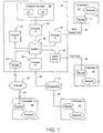
- a network service provider maintains a secure customer access network (SCAN) 10 that allows unrelated customers at remote physical sites 12, 14, 16, 18 to receive network services 20, such as network management, trouble ticketing and Internet access, through a common, secure architectural interface.
- the SCAN 10 employs network switching, virtual local area network (VLAN) and firewall technology to provide the network services 20 in a secure manner to a virtually unlimited number of customers using only a minimum of network components.
- the SCAN 10 is capable of providing the network services 20 over a wide variety of connections, including frame relay (FR), private leased line, asynchronous transfer mode (ATM), Point-to-Point Protocol (PPP) and Integrated Services Digital Network (ISDN) connections.
- FR frame relay
- ATM asynchronous transfer mode
- PPP Point-to-Point Protocol
- ISDN Integrated Services Digital Network
- the SCAN 10 also includes a router 23, e.g., a Cisco 7000 router, that maintains a full Internet route table and that serves as a full Border Gateway Protocol (BGP) peer to several Internet service providers (ISPs).
- This router 23 allows a SCAN customer to access the network services 20 and the customer's own network via the Internet 25 and to access the Internet 25 from the customer's network via the SCAN 10.
- Each customer site 12, 14, 16, 18 typically includes a computer subnetwork, e.g., a local area network (LAN) 15, and a router 17 capable of connecting the LAN 15 to other computer networks, including the Internet 25.
- LAN local area network
- Some of the network services 20 provided by the SCAN 10 may be implemented as executable programs running on programmable computers 11, 13, e.g., network server computers, in a subnetwork maintained by the network service provider.
- each computer 11, 13 in the subnetwork is dedicated to providing one of the network services.
- the computers 11, 13 may operate under different operating systems, e.g., Unix and Windows NT, or they all may run under the same operating system.
- the network services may be provided as described in "Providing Network Services Through a Common Interface" in International Publication WO 99/46692.
- the SCAN 10 processes and generate information that is proprietary to individual customers, so the SCAN 10 must ensure that information exchanged between the group of network services 20 and any given customer cannot be accessed by anyone other than that customer.
- the network service provider also may want to prevent unauthorized communications between customers through the SCAN 10.
- the SCAN 10 recognizes each subnetwork of computers as a unique physical domain, or group, each of which must be protected from users in the other groups.
- the SCAN 10 treats each customer site 12, 14, 16, 18 as a unique group and treats any other subnetwork maintained by the network service provider, e.g., a subnetwork connecting administrative personnel, as a separate group, and it treats the Internet router 23 as a separate group.
- VLANs virtual LANs
- Each VLAN represents a logical connection created by the LAN switch 30 between computers located in different physical domains.
- the LAN switch 30, through VLANs allows computers in different logical networks to communicate with each other, via connections made either internally within the LAN switch 30 or externally through a security device, such as a firewall.
- the LAN switch 30 allows users at the customer sites 12, 14, 16, 18 to access the network services 10 maintained by the network provider.
- the SCAN 10 may use several policies to define VLANs, including any of the following: (1) a port-based policy, which assigns computers in the various groups to VLANs based on the physical ports to which they attach in the SCAN 10; (2) a media access control (MAC) address-based policy, which defines VLANs based on the physical layer addresses of the computers in the various groups; and (3) an Internet Protocol (IP) address policy, which defines VLANs based on the network layer addresses of the computers in the various groups.
- MAC media access control
- IP Internet Protocol
- the SCAN 10 protects the groups and the information flowing between groups by requiring all group-to-group communications to pass through at least one of four firewalls 22, 24, 26, 28, each of which implements a single, static routing policy.
- the SCAN 10 further protects the group of network services by requiring all communications between this group and any other group to pass through two of the four firewalls.
- each of the firewalls may be implemented as a network server computer 50, e.g., a Sun Sparc workstation, running an executable program 68, such as Checkpoint's "Firewall-1" software, that has been loaded from a fixed storage medium, e.g., a hard disk 66, into the computer's system memory 54.
- Each firewall routes TCP/IP (Transmission Control Protocol/Internet Protocol) data packets according to a static routing policy defined by a route table 70, which also may be stored in the hard disk 66. Packets that meet all of the conditions prescribed in a firewall's route table are forwarded by the firewall to the appropriate destination; packets that do not meet the prescribed conditions are discarded.
- a static routing policy in each firewall ensures that no one other that the network service provider can change the routing policy within the SCAN 10, which in turn ensures that the network service provider's customers receive secure access to the SCAN 10. Also, because the routing policy is static, the firewalls do not propagate any routing information to the customer sites 12, 14, 16, 18 or to the Internet 25. Instead, the routers 17 in the customer sites are configured with static routes to the SCAN 10, as discussed below.
- each of the four firewalls 22, 24, 26, 28 implements a single route policy that pertains only to transactions involving certain physical domains (groups).
- the first firewall 22 (Firewall A) protects the group of network services 20 from unwanted penetration by users in other groups by inspecting all traffic passing to and from the network services 20, including communications among the network services 20 themselves.
- the route policy implemented in the first firewall 22 includes two rulesets (listed as source/destination/service): (1) a "service group/any/any” ruleset, which allows the network service provider to access any other group using any of the network services; and (2) a "customer/service group/service” ruleset, which allows any bona fide customer to access the group of network services 20 using any service for which the customer subscribes.
- the other three firewalls 24, 26, 28 serve to ensure that only bona fide customers of the network service provider are able to access the SCAN 10.
- Each of these firewalls provides access only to those customers that meet certain service-subscription criteria.
- the second firewall 24 (Firewall B) provides access only to customers that access the network services 20 directly through the SCAN 10 and that do not receive Internet access from any source other than the network service provider.
- This type of customer is equipped with a static route to the second firewall 24 in its internal router.
- the route policy implemented in the second firewall 24 includes three rulesets: (1) a "service group/any/any” ruleset, which allows the network service provider to access any other group using any of the network services; (2) a “customer/firewall A/service” ruleset, which allows the customer to access, through the first firewall 22, the group of network services using any service for which the customer subscribes; and (3) a "customer/Internet/services" ruleset, which allows the customer to access the Internet via the Internet router 23 using any service for which the customer subscribes.
- the third ruleset may be defined to limit Internet access to certain users within the customer's physical domain or to certain services, e.g., e-mail only.
- the third firewall 26 provides access only to customers that access the network services 20 directly through the SCAN 10 and that receive Internet service from a source other than the network service provider. This type of customer is equipped with a static route to the third firewall 26 in its internal router.
- the route policy implemented in the third firewall 26 includes two rulesets: (1) a "service group/any/any” ruleset, which allows the network service provider to access any other group using any of the network services; and (2) a "customer/firewall A/service” ruleset, which allows the customer to access, through the first firewall 22, the group of network services using any service for which the customer subscribes.
- the fourth firewall (Firewall D) 28 provides access to customers that receive any of the network services 20 via the Internet 25.
- the route policy implemented in the fourth firewall 28 includes two rulesets: (1) a "service group/any/any” ruleset, which allows the network service provider to access any other group using any of the network services; and (2) a "customer-via-Internet/firewall A/service” ruleset, which allows the customer to access, through the first firewall 22, the group of network services using any service for which the customer subscribes.
- Customers that access the SCAN 10 via the Internet 25 may experience reduced transmission bandwidth and extra delays beyond the control of the network service provider.
- the customers of the network service provider can connect to the SCAN 10 using a variety of connection technologies, including frame relay, ATM, PPP, ISDN and Internet connections.
- the first customer site (Customer I) 12 in FIG. 1 accesses the SCAN 10 through a PPP line 34 that terminates directly at either the second firewall 24 or the third firewall 26, depending on whether the customer 12 receives Internet service from any source other than the network service provider, as discussed above.
- a PPP link typically involves a dedicated physical connection, or physical port, at a firewall and therefore requires the customer to lease the link from the network service provider.
- Each PPP link also accounts for one IP interface at the firewall.
- the second customer site (Customer II) 14 in FIG. 1 accesses the SCAN 10 through a link 36 to a frame relay 32 that terminates directly at either the second firewall 24 or the third firewall 26.
- each link 38 from a frame relay to a firewall requires a dedicated synchronous port on the firewall, but since each frame relay link 38 can support multiple permanent virtual circuits (PVCs), and therefore multiple customers, each firewall can support a considerable number of customers via frame relay connections.
- PVCs permanent virtual circuits
- the third customer site (Customer III) 16 in FIG. 1 accesses the SCAN 10 through an ISDN line 40 that terminates at an ISDN server 42, e.g., a Cisco 4500M server, within the SCAN 10.
- the ISDN server 42 connects physically to the LAN switch 30, which in turn forms a logical connection between the ISDN server 42 and either the second firewall 24 or the third firewall 26, depending upon whether the customer 16 receives Internet access from any source other than the network service provider. Because the ISDN server 42 is used to terminate ISDN links to the SCAN 10, the second and third firewalls each need dedicate only one IP interface to service all customers with ISDN links.
- the ISDN server 42 may provide additional security for the SCAN 10 by ending each ISDN call as soon as it begins, using the standard ISDN "Caller ID” feature to reestablish a connection with the caller, and then using an authentication protocol, such as the "Challenge Handshake Authentication Protocol” (CHAP), to verify that the caller is a bona fide customer.
- an authentication protocol such as the "Challenge Handshake Authentication Protocol” (CHAP)
- the fourth customer site (Customer IV) 18 in FIG. 1 accesses the SCAN 10 via a link 44 to the Internet 25.
- This customer also may access the SCAN 10 in other ways, e.g., through a frame relay or PPP connection, via either the second firewall 24 or the third firewall 26, as discussed above.
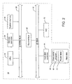
- each firewall is implemented as a programmable computer 50 having, among other things, a central processing unit (CPU) 52, a memory controller 54, and a system memory 56 coupled to a system bus 58.
- the system memory 56 may include a random access memory (RAM) 106 and a non-volatile memory 108, e.g., a writable read-only memory such as a flash ROM.
- the computer 50 also includes a fixed storage medium, such as a hard disk 66, and a hard disk controller 64 coupled via an input/output (I/O) bus 62, which in turn is coupled to the CPU bus 58 by a bus interface device 60.
- I/O input/output
- the computer 50 may be preprogrammed, e.g., in ROM, to serve as a firewall, or it may be programmed by loading an executable program 68 from a storage medium, such as the hard disk 66, a floppy disk or a CD-ROM, into system memory 56.
- the executable program 68 accesses a route table 70, which may be stored on the hard disk 50, to determine how to route information through the firewall.
- the computer 50 also includes a network interface controller 72 coupled to the I/O bus 62 which enables the computer 50 to connect to one or more computer networks.
Landscapes
- Engineering & Computer Science (AREA)
- Computer Security & Cryptography (AREA)
- Computer Networks & Wireless Communication (AREA)
- Signal Processing (AREA)
- Computer Hardware Design (AREA)
- Computing Systems (AREA)
- General Engineering & Computer Science (AREA)
- Data Exchanges In Wide-Area Networks (AREA)
- Computer And Data Communications (AREA)
- Multi Processors (AREA)
Claims (12)
- Computernetzwerk (10), das einen oder mehrere Dienste-Computer (11, 13) enthält, die dafür konfiguriert sind, Netzwerkdienste (20) bereitzustellen, wobei das Computernetzwerk (10) Folgendes umfasst:dadurch gekennzeichnet, dass die logische Rundsendedomäne unter Verwendung von wenigstens zwei Routing-Vorrichtungen (22, 24, 26, 28) implementiert ist, die jeweils eine einzelne statische Routenvorschrift implementieren, die den Verkehrsfluss zwischen den Netzwerkdiensten (20) und den mehreren Netzwerk-Clientcomputern (12, 14, 16, 18) regelt und einen unbefugten Zugriff auf das Computernetzwerk (10) verhindert, wobei jede der Routing-Vorrichtungen (22, 24, 26, 28) ein unabhängiges Routing zu den Netzwerkdiensten (20) bereitstellt.eine oder mehrere Verbindungsvorrichtungen (34, 36, 40, 44), die es mehreren Netzwerk-Clientcomputern (12, 14, 16, 18) gestatten, über das Computernetzwerk (10) auf die Netzwerkdienste (20) zuzugreifen, wobei jeder der mehreren Netzwerk-Clientcomputer (12, 14, 16, 18) einer physischen Gruppe aus Computern zugeordnet ist, undeine logische Verbindungsvorrichtung (30), die zwischen den Dienste-Computern (11, 13) und den mehreren Netzwerk-Clientcomputern (12, 14, 16, 18) angeschlossen ist und dafür konfiguriert ist, logische Rundsendedomänen unter den Netzwerkdiensten (20) und den mehreren Netzwerk-Clientcomputern (12, 14, 16, 18) zu erzeugen, wobei jede logische Rundsendedomäne eine Gruppierung aus ausgewählten Netzwerkdiensten (20) und wenigstens einen der mehreren Netzwerk-Clientcomputer (12, 14, 16, 18) umfasst,
- Computernetzwerk gemäß Anspruch 1, wobei die logische Verbindungsvorrichtung (30) so konfiguriert ist, dass sie einen Zugriff über ein Public Frame Relay (32) oder über eine PPP-Verbindung (34) oder über eine ISDN-Verbindung (40) oder über das Internet (25) gestattet.
- Computernetzwerk gemäß Anspruch 1 oder 2, wobei die statische Routenvorschrift mittels einer statischen Routentabelle definiert wird.
- Computernetzwerk gemäß einem der Ansprüche 1 bis 3, wobei die mehreren Netzwerk-Clientcomputer (12, 14, 16, 18) zu mehreren logischen Rundsendedomänen gehören.
- Computernetzwerk gemäß einem der Ansprüche 1 bis 4, wobei die logischen Rundsendedomänen eine Kommunikation zwischen den mehreren Netzwerk-Clientcomputern (12, 14, 16, 18) intern innerhalb einer Vermittlungsstelle (30) gestatten.
- Computernetzwerk gemäß einem der Ansprüche 1 bis 5, wobei die logischen Rundsendedomänen eine Kommunikation zwischen den mehreren Netzwerk-Clientcomputern (12, 14, 16, 18) extern über die Routing-Vorrichtung (22, 24, 26, 28) gestatten.
- Verfahren zum Bereitstellen von Netzwerkdiensten (20) an mehrere Netzwerk-Clientcomputer (12, 14, 16, 18) über ein Computernetzwerk (10), wobei das Verfahren umfasst:dadurch gekennzeichnet, dasses den Netzwerk-Clientcomputern (12, 14, 16, 18) zu gestatten, über eine oder mehrere Verbindungsvorrichtungen (34, 36, 40, 44) in dem Computernetzwerk (10) auf die Netzwerkdienste (20) zuzugreifen,logische Rundsendedomänen unter den Netzwerkdiensten (20) und den Netzwerk-Clientcomputern (12, 14, 16, 18) zu erzeugen, undzu erzwingen, dass der gesamte Verkehr innerhalb des Netzwerkdienstes (20) durch eine erste Routing-Vorrichtung (22, 24, 26, 28) hindurch verläuft,
die erste Routing-Vorrichtung (22, 24, 26, 28) eine statische Routenvorschrift implementiert,
und des Weiteren dadurch gekennzeichnet, dass
erzwungen wird, dass der gesamte Verkehr zwischen den Netzwerkdiensten (20) und den Netzwerk-Clientcomputern (12, 14, 16, 18) durch eine zweite (17) Routing-Vorrichtung hindurch verläuft, die eine statische Routenvorschrift implementiert,
wobei das Routing unabhängig durch die erste Routing-Vorrichtung (22, 24, 26, 28) und durch die zweite Routing-Vorrichtung (22, 24, 26, 28) bereitgestellt wird. - Verfahren gemäß Anspruch 7, das des Weiteren umfasst, es den Netzwerk-Clientcomputern (12, 14, 16, 18) zu gestatten, über ein Public Frame Relay (32) oder über eine PPP-Verbindung (34) oder über eine ISDN-Verbindung (40) oder über das Internet (25) auf das Netzwerk zuzugreifen.
- Verfahren gemäß Anspruch 7 oder 8, wobei die statische Routenvorschrift mittels einer statischen Routentabelle definiert wird.
- Verfahren gemäß einem der Ansprüche 7 bis 9, wobei die Netzwerk-Clientcomputer (12, 14, 16, 18) zu mehreren logischen Rundsendedomänen gehören.
- Verfahren gemäß einem der Ansprüche 7 bis 10, das des Weiteren umfasst, durch die logischen Rundsendedomänen eine Kommunikation zwischen Netzwerk-Clientcomputern (12, 14, 16, 18) intern innerhalb einer Vermittlungsstelle (30) zu gestatten.
- Verfahren gemäß einem der Ansprüche 7 bis 11, das des Weiteren umfasst, durch die logischen Rundsendedomänen eine Kommunikation zwischen Netzwerk-Clientcomputern (12, 14, 16, 18) extern über die Routing-Vorrichtung (22, 24, 26, 28) zu gestatten.
Applications Claiming Priority (3)
| Application Number | Priority Date | Filing Date | Title |
|---|---|---|---|
| US3919798A | 1998-03-13 | 1998-03-13 | |
| US39197 | 1998-03-13 | ||
| PCT/US1999/004624 WO1999046906A1 (en) | 1998-03-13 | 1999-03-03 | Providing secure access to network services |
Publications (2)
| Publication Number | Publication Date |
|---|---|
| EP1062784A1 EP1062784A1 (de) | 2000-12-27 |
| EP1062784B1 true EP1062784B1 (de) | 2005-11-23 |
Family
ID=21904190
Family Applications (1)
| Application Number | Title | Priority Date | Filing Date |
|---|---|---|---|
| EP99909768A Expired - Lifetime EP1062784B1 (de) | 1998-03-13 | 1999-03-03 | Sicherer zugriff auf netzwerkdienste |
Country Status (7)
| Country | Link |
|---|---|
| US (1) | US6877041B2 (de) |
| EP (1) | EP1062784B1 (de) |
| AU (1) | AU771269B2 (de) |
| BR (2) | BR9909650A (de) |
| CA (1) | CA2323766C (de) |
| DE (1) | DE69928504T2 (de) |
| WO (1) | WO1999046906A1 (de) |
Families Citing this family (32)
| Publication number | Priority date | Publication date | Assignee | Title |
|---|---|---|---|---|
| US6317837B1 (en) | 1998-09-01 | 2001-11-13 | Applianceware, Llc | Internal network node with dedicated firewall |
| US6701432B1 (en) * | 1999-04-01 | 2004-03-02 | Netscreen Technologies, Inc. | Firewall including local bus |
| US7107612B1 (en) | 1999-04-01 | 2006-09-12 | Juniper Networks, Inc. | Method, apparatus and computer program product for a network firewall |
| US6986160B1 (en) * | 2001-08-31 | 2006-01-10 | Mcafee, Inc. | Security scanning system and method utilizing generic IP addresses |
| JP3875107B2 (ja) * | 2002-01-10 | 2007-01-31 | 株式会社エヌ・ティ・ティ・ドコモ | パケット交換システム、パケット交換方法、ルーティング装置、パケットデータ及びその生成方法 |
| US20030177390A1 (en) * | 2002-03-15 | 2003-09-18 | Rakesh Radhakrishnan | Securing applications based on application infrastructure security techniques |
| US7379857B2 (en) * | 2002-05-10 | 2008-05-27 | Lockheed Martin Corporation | Method and system for simulating computer networks to facilitate testing of computer network security |
| US20040019465A1 (en) * | 2002-05-13 | 2004-01-29 | Kerr James W. | Event router and method for handling events in distributing computing applications |
| US7194767B1 (en) * | 2002-06-28 | 2007-03-20 | Sprint Communications Company L.P. | Screened subnet having a secured utility VLAN |
| US20040133772A1 (en) * | 2003-01-07 | 2004-07-08 | Battelle Memorial Institute | Firewall apparatus and method for voice over internet protocol |
| US8458453B1 (en) | 2004-06-11 | 2013-06-04 | Dunti Llc | Method and apparatus for securing communication over public network |
| US8732808B2 (en) * | 2004-09-08 | 2014-05-20 | Cradlepoint, Inc. | Data plan activation and modification |
| US9237102B2 (en) * | 2004-09-08 | 2016-01-12 | Cradlepoint, Inc. | Selecting a data path |
| US20070254727A1 (en) * | 2004-09-08 | 2007-11-01 | Pat Sewall | Hotspot Power Regulation |
| US9232461B2 (en) * | 2004-09-08 | 2016-01-05 | Cradlepoint, Inc. | Hotspot communication limiter |
| US20090172658A1 (en) * | 2004-09-08 | 2009-07-02 | Steven Wood | Application installation |
| US8477639B2 (en) * | 2004-09-08 | 2013-07-02 | Cradlepoint, Inc. | Communicating network status |
| US9294353B2 (en) * | 2004-09-08 | 2016-03-22 | Cradlepoint, Inc. | Configuring a wireless router |
| US7962569B2 (en) * | 2004-09-08 | 2011-06-14 | Cradlepoint, Inc. | Embedded DNS |
| US8249052B2 (en) * | 2004-09-08 | 2012-08-21 | Cradlepoint, Inc. | Automated access of an enhanced command set |
| US7764784B2 (en) * | 2004-09-08 | 2010-07-27 | Cradlepoint, Inc. | Handset cradle |
| US8914868B2 (en) * | 2006-03-03 | 2014-12-16 | Hewlett-Packard Development Company, L.P. | Vendor-neutral policy based mechanism for enabling firewall service in an MPLS-VPN service network |
| US9021081B2 (en) * | 2007-02-12 | 2015-04-28 | Cradlepoint, Inc. | System and method for collecting individualized network usage data in a personal hotspot wireless network |
| US8644272B2 (en) * | 2007-02-12 | 2014-02-04 | Cradlepoint, Inc. | Initiating router functions |
| US10135677B1 (en) | 2012-07-06 | 2018-11-20 | Cradlepoint, Inc. | Deployment of network-related features over cloud network |
| US10110417B1 (en) | 2012-07-06 | 2018-10-23 | Cradlepoint, Inc. | Private networks overlaid on cloud infrastructure |
| US10601653B2 (en) | 2012-07-06 | 2020-03-24 | Cradlepoint, Inc. | Implicit traffic engineering |
| US9992062B1 (en) | 2012-07-06 | 2018-06-05 | Cradlepoint, Inc. | Implicit traffic engineering |
| US10177957B1 (en) | 2012-07-06 | 2019-01-08 | Cradlepoint, Inc. | Connecting a cloud network to the internet |
| US10560343B1 (en) | 2012-07-06 | 2020-02-11 | Cradlepoint, Inc. | People centric management of cloud networks via GUI |
| US10880162B1 (en) | 2012-07-06 | 2020-12-29 | Cradlepoint, Inc. | Linking logical broadcast domains |
| US9503397B2 (en) | 2013-01-15 | 2016-11-22 | International Business Machines Corporation | Applying a client policy to a group of channels |
Family Cites Families (13)
| Publication number | Priority date | Publication date | Assignee | Title |
|---|---|---|---|---|
| US5835726A (en) * | 1993-12-15 | 1998-11-10 | Check Point Software Technologies Ltd. | System for securing the flow of and selectively modifying packets in a computer network |
| US5734865A (en) * | 1995-06-07 | 1998-03-31 | Bull Hn Information Systems Inc. | Virtual local area network well-known port routing mechanism for mult--emulators in an open system environment |
| US6041166A (en) * | 1995-07-14 | 2000-03-21 | 3Com Corp. | Virtual network architecture for connectionless LAN backbone |
| US5898830A (en) * | 1996-10-17 | 1999-04-27 | Network Engineering Software | Firewall providing enhanced network security and user transparency |
| US5920699A (en) * | 1996-11-07 | 1999-07-06 | Hewlett-Packard Company | Broadcast isolation and level 3 network switch |
| US5835727A (en) * | 1996-12-09 | 1998-11-10 | Sun Microsystems, Inc. | Method and apparatus for controlling access to services within a computer network |
| US6012088A (en) * | 1996-12-10 | 2000-01-04 | International Business Machines Corporation | Automatic configuration for internet access device |
| US6009475A (en) * | 1996-12-23 | 1999-12-28 | International Business Machines Corporation | Filter rule validation and administration for firewalls |
| US6128665A (en) * | 1996-12-30 | 2000-10-03 | Cabletron Systems, Inc. | System for broadcasting messages to each of default VLAN ports in subset of ports defined as VLAN ports |
| JP3180054B2 (ja) * | 1997-05-16 | 2001-06-25 | インターナショナル・ビジネス・マシーンズ・コーポレ−ション | ネットワーク・セキュリティ・システム |
| US6230194B1 (en) * | 1997-07-14 | 2001-05-08 | Freegate Corporation | Upgrading a secure network interface |
| US6339595B1 (en) * | 1997-12-23 | 2002-01-15 | Cisco Technology, Inc. | Peer-model support for virtual private networks with potentially overlapping addresses |
| US6484261B1 (en) * | 1998-02-17 | 2002-11-19 | Cisco Technology, Inc. | Graphical network security policy management |
-
1999
- 1999-03-03 BR BR9909650-1A patent/BR9909650A/pt not_active IP Right Cessation
- 1999-03-03 BR BR9909649-8A patent/BR9909649A/pt not_active IP Right Cessation
- 1999-03-03 WO PCT/US1999/004624 patent/WO1999046906A1/en not_active Ceased
- 1999-03-03 CA CA002323766A patent/CA2323766C/en not_active Expired - Lifetime
- 1999-03-03 AU AU28900/99A patent/AU771269B2/en not_active Ceased
- 1999-03-03 DE DE69928504T patent/DE69928504T2/de not_active Expired - Lifetime
- 1999-03-03 EP EP99909768A patent/EP1062784B1/de not_active Expired - Lifetime
-
2001
- 2001-07-03 US US09/898,977 patent/US6877041B2/en not_active Expired - Lifetime
Also Published As
| Publication number | Publication date |
|---|---|
| BR9909649A (pt) | 2002-03-05 |
| CA2323766C (en) | 2007-12-04 |
| WO1999046906A1 (en) | 1999-09-16 |
| CA2323766A1 (en) | 1999-09-16 |
| AU2890099A (en) | 1999-09-27 |
| US20010042215A1 (en) | 2001-11-15 |
| BR9909650A (pt) | 2002-03-05 |
| EP1062784A1 (de) | 2000-12-27 |
| US6877041B2 (en) | 2005-04-05 |
| AU771269B2 (en) | 2004-03-18 |
| DE69928504D1 (de) | 2005-12-29 |
| DE69928504T2 (de) | 2006-07-27 |
Similar Documents
| Publication | Publication Date | Title |
|---|---|---|
| EP1062784B1 (de) | Sicherer zugriff auf netzwerkdienste | |
| EP1690403B1 (de) | Firewall mit zwei betriebsarten | |
| US7131141B1 (en) | Method and apparatus for securely connecting a plurality of trust-group networks, a protected resource network and an untrusted network | |
| US8528070B2 (en) | System and method for secure service delivery | |
| US7389358B1 (en) | Distributed virtual system to support managed, network-based services | |
| US5968176A (en) | Multilayer firewall system | |
| Schultz | Types of Firewalls | |
| US7379465B2 (en) | Tunneling scheme optimized for use in virtual private networks | |
| EP1418730B1 (de) | Kreuzungen von virtuellen, privaten Netzwerken basiert auf Zertifikate | |
| US7756022B1 (en) | Secure hidden route in a data network | |
| GB2418110A (en) | Controlling traffic passed between logical zones in a network representing a layered tunnel model | |
| WO2005112398A1 (en) | Firewall load balancing using a single physical device | |
| US7024686B2 (en) | Secure network and method of establishing communication amongst network devices that have restricted network connectivity | |
| JP2006254430A (ja) | アプリケーションサーバ機能を促進するための方法およびアプリケーションサーバ機能を含むアクセスノード | |
| US20010037384A1 (en) | System and method for implementing a virtual backbone on a common network infrastructure | |
| EP1413095B1 (de) | System und verfahren zur bereitstellung von diensten in virtuellen privatnetzen | |
| Ranum | An Internet Firewall | |
| GB2330991A (en) | Routing data packets | |
| Terada et al. | Access control for inter-organizational computer network environment | |
| WO2004080024A1 (en) | A packet forwarding apparatus | |
| Terada1 et al. | User Access domain management system-ADAMS | |
| Armitage et al. | Internet Engineering Task Force B. Gleeson, A. Lin INTERNET DRAFT Nortel Networks Expires April 2000 J. Heinanen Telia Finland | |
| Murayama | User Access Domain Management System |
Legal Events
| Date | Code | Title | Description |
|---|---|---|---|
| PUAI | Public reference made under article 153(3) epc to a published international application that has entered the european phase |
Free format text: ORIGINAL CODE: 0009012 |
|
| 17P | Request for examination filed |
Effective date: 20001013 |
|
| AK | Designated contracting states |
Kind code of ref document: A1 Designated state(s): DE FR GB |
|
| 17Q | First examination report despatched |
Effective date: 20030122 |
|
| RAP1 | Party data changed (applicant data changed or rights of an application transferred) |
Owner name: SCHLUMBERGER OMNES, INC. |
|
| GRAP | Despatch of communication of intention to grant a patent |
Free format text: ORIGINAL CODE: EPIDOSNIGR1 |
|
| GRAS | Grant fee paid |
Free format text: ORIGINAL CODE: EPIDOSNIGR3 |
|
| GRAA | (expected) grant |
Free format text: ORIGINAL CODE: 0009210 |
|
| AK | Designated contracting states |
Kind code of ref document: B1 Designated state(s): DE FR GB |
|
| REG | Reference to a national code |
Ref country code: GB Ref legal event code: FG4D |
|
| REF | Corresponds to: |
Ref document number: 69928504 Country of ref document: DE Date of ref document: 20051229 Kind code of ref document: P |
|
| ET | Fr: translation filed | ||
| PLBE | No opposition filed within time limit |
Free format text: ORIGINAL CODE: 0009261 |
|
| STAA | Information on the status of an ep patent application or granted ep patent |
Free format text: STATUS: NO OPPOSITION FILED WITHIN TIME LIMIT |
|
| 26N | No opposition filed |
Effective date: 20060824 |
|
| REG | Reference to a national code |
Ref country code: DE Ref legal event code: R082 Ref document number: 69928504 Country of ref document: DE Representative=s name: DIEHL & PARTNER GBR, DE |
|
| REG | Reference to a national code |
Ref country code: GB Ref legal event code: 732E Free format text: REGISTERED BETWEEN 20120119 AND 20120125 |
|
| REG | Reference to a national code |
Ref country code: FR Ref legal event code: TP Owner name: SCHLUMBERGER TECHNOLOGY CORPORATION, US Effective date: 20120106 |
|
| REG | Reference to a national code |
Ref country code: DE Ref legal event code: R082 Ref document number: 69928504 Country of ref document: DE Representative=s name: PATENT- UND RECHTSANWAELTE DIEHL & PARTNER GBR, DE Effective date: 20120123 Ref country code: DE Ref legal event code: R082 Ref document number: 69928504 Country of ref document: DE Representative=s name: DIEHL & PARTNER GBR, DE Effective date: 20120123 Ref country code: DE Ref legal event code: R081 Ref document number: 69928504 Country of ref document: DE Owner name: COMCAST CABLE COMMUNICATIONS, LLC, PHILADELPHI, US Free format text: FORMER OWNER: SCHLUMBERGER OMNES, INC., HOUSTON, TEX., US Effective date: 20120123 Ref country code: DE Ref legal event code: R081 Ref document number: 69928504 Country of ref document: DE Owner name: COMCAST CABLE COMMUNICATIONS, LLC, US Free format text: FORMER OWNER: SCHLUMBERGER OMNES, INC., HOUSTON, US Effective date: 20120123 |
|
| REG | Reference to a national code |
Ref country code: DE Ref legal event code: R082 Ref document number: 69928504 Country of ref document: DE Representative=s name: DIEHL & PARTNER GBR, DE |
|
| REG | Reference to a national code |
Ref country code: DE Ref legal event code: R082 Ref document number: 69928504 Country of ref document: DE Representative=s name: PATENT- UND RECHTSANWAELTE DIEHL & PARTNER GBR, DE Effective date: 20130910 Ref country code: DE Ref legal event code: R082 Ref document number: 69928504 Country of ref document: DE Representative=s name: DIEHL & PARTNER GBR, DE Effective date: 20130910 Ref country code: DE Ref legal event code: R081 Ref document number: 69928504 Country of ref document: DE Owner name: COMCAST CABLE COMMUNICATIONS, LLC, PHILADELPHI, US Free format text: FORMER OWNER: SCHLUMBERGER TECHNOLOGY CORP., SUGAR LAND, TEX., US Effective date: 20130910 Ref country code: DE Ref legal event code: R081 Ref document number: 69928504 Country of ref document: DE Owner name: COMCAST CABLE COMMUNICATIONS, LLC, US Free format text: FORMER OWNER: SCHLUMBERGER TECHNOLOGY CORP., SUGAR LAND, US Effective date: 20130910 |
|
| REG | Reference to a national code |
Ref country code: GB Ref legal event code: 732E Free format text: REGISTERED BETWEEN 20131010 AND 20131016 |
|
| REG | Reference to a national code |
Ref country code: FR Ref legal event code: TP Owner name: COMCAST CABLE COMMUNICATIONS, LLC, US Effective date: 20131022 |
|
| REG | Reference to a national code |
Ref country code: FR Ref legal event code: PLFP Year of fee payment: 18 |
|
| REG | Reference to a national code |
Ref country code: FR Ref legal event code: PLFP Year of fee payment: 19 |
|
| REG | Reference to a national code |
Ref country code: FR Ref legal event code: PLFP Year of fee payment: 20 |
|
| PGFP | Annual fee paid to national office [announced via postgrant information from national office to epo] |
Ref country code: GB Payment date: 20180327 Year of fee payment: 20 |
|
| PGFP | Annual fee paid to national office [announced via postgrant information from national office to epo] |
Ref country code: FR Payment date: 20180326 Year of fee payment: 20 |
|
| PGFP | Annual fee paid to national office [announced via postgrant information from national office to epo] |
Ref country code: DE Payment date: 20180328 Year of fee payment: 20 |
|
| REG | Reference to a national code |
Ref country code: DE Ref legal event code: R071 Ref document number: 69928504 Country of ref document: DE |
|
| REG | Reference to a national code |
Ref country code: GB Ref legal event code: PE20 Expiry date: 20190302 |
|
| PG25 | Lapsed in a contracting state [announced via postgrant information from national office to epo] |
Ref country code: GB Free format text: LAPSE BECAUSE OF EXPIRATION OF PROTECTION Effective date: 20190302 |