EP1062987A2 - Implantierbare medizinische Vorrichtung - Google Patents
Implantierbare medizinische Vorrichtung Download PDFInfo
- Publication number
- EP1062987A2 EP1062987A2 EP00305271A EP00305271A EP1062987A2 EP 1062987 A2 EP1062987 A2 EP 1062987A2 EP 00305271 A EP00305271 A EP 00305271A EP 00305271 A EP00305271 A EP 00305271A EP 1062987 A2 EP1062987 A2 EP 1062987A2
- Authority
- EP
- European Patent Office
- Prior art keywords
- atrial
- medical device
- implantable medical
- waves
- wave
- Prior art date
- Legal status (The legal status is an assumption and is not a legal conclusion. Google has not performed a legal analysis and makes no representation as to the accuracy of the status listed.)
- Granted
Links
- 230000002265 prevention Effects 0.000 claims abstract description 51
- 206010003130 Arrhythmia supraventricular Diseases 0.000 claims abstract description 17
- 230000003595 spectral effect Effects 0.000 claims abstract description 11
- 230000001746 atrial effect Effects 0.000 claims description 113
- 230000004913 activation Effects 0.000 claims description 9
- 238000001994 activation Methods 0.000 claims description 9
- 238000004458 analytical method Methods 0.000 claims description 8
- 238000001514 detection method Methods 0.000 claims description 8
- 238000012935 Averaging Methods 0.000 claims description 5
- 206010003658 Atrial Fibrillation Diseases 0.000 description 54
- 210000005245 right atrium Anatomy 0.000 description 14
- 210000005246 left atrium Anatomy 0.000 description 13
- 239000004020 conductor Substances 0.000 description 12
- 238000002560 therapeutic procedure Methods 0.000 description 12
- 230000002861 ventricular Effects 0.000 description 10
- 230000000747 cardiac effect Effects 0.000 description 9
- 238000010183 spectrum analysis Methods 0.000 description 8
- 210000002837 heart atrium Anatomy 0.000 description 5
- 238000000034 method Methods 0.000 description 5
- 238000011022 operating instruction Methods 0.000 description 5
- 210000005241 right ventricle Anatomy 0.000 description 5
- 230000000694 effects Effects 0.000 description 4
- 238000007726 management method Methods 0.000 description 4
- 206010040639 Sick sinus syndrome Diseases 0.000 description 3
- 206010049447 Tachyarrhythmia Diseases 0.000 description 3
- 208000001871 Tachycardia Diseases 0.000 description 3
- 210000003748 coronary sinus Anatomy 0.000 description 3
- 230000033764 rhythmic process Effects 0.000 description 3
- 230000000638 stimulation Effects 0.000 description 3
- 210000003462 vein Anatomy 0.000 description 3
- 238000013459 approach Methods 0.000 description 2
- 238000013194 cardioversion Methods 0.000 description 2
- 230000008859 change Effects 0.000 description 2
- 238000010586 diagram Methods 0.000 description 2
- 238000002651 drug therapy Methods 0.000 description 2
- 230000001575 pathological effect Effects 0.000 description 2
- 230000004044 response Effects 0.000 description 2
- 230000035945 sensitivity Effects 0.000 description 2
- 206010007559 Cardiac failure congestive Diseases 0.000 description 1
- 206010019280 Heart failures Diseases 0.000 description 1
- 206010020850 Hyperthyroidism Diseases 0.000 description 1
- 206010033557 Palpitations Diseases 0.000 description 1
- 206010003119 arrhythmia Diseases 0.000 description 1
- 238000007405 data analysis Methods 0.000 description 1
- 201000010099 disease Diseases 0.000 description 1
- 208000037265 diseases, disorders, signs and symptoms Diseases 0.000 description 1
- 208000002173 dizziness Diseases 0.000 description 1
- 206010020871 hypertrophic cardiomyopathy Diseases 0.000 description 1
- 210000005240 left ventricle Anatomy 0.000 description 1
- 238000005259 measurement Methods 0.000 description 1
- 230000004048 modification Effects 0.000 description 1
- 238000012986 modification Methods 0.000 description 1
- 238000012544 monitoring process Methods 0.000 description 1
- 230000001314 paroxysmal effect Effects 0.000 description 1
- 230000000737 periodic effect Effects 0.000 description 1
- 208000037821 progressive disease Diseases 0.000 description 1
- 238000011160 research Methods 0.000 description 1
- 238000007920 subcutaneous administration Methods 0.000 description 1
- 230000009466 transformation Effects 0.000 description 1
- 230000000472 traumatic effect Effects 0.000 description 1
- 230000001960 triggered effect Effects 0.000 description 1
- 210000002620 vena cava superior Anatomy 0.000 description 1
Images

Classifications
-
- A—HUMAN NECESSITIES
- A61—MEDICAL OR VETERINARY SCIENCE; HYGIENE
- A61N—ELECTROTHERAPY; MAGNETOTHERAPY; RADIATION THERAPY; ULTRASOUND THERAPY
- A61N1/00—Electrotherapy; Circuits therefor
- A61N1/18—Applying electric currents by contact electrodes
- A61N1/32—Applying electric currents by contact electrodes alternating or intermittent currents
- A61N1/36—Applying electric currents by contact electrodes alternating or intermittent currents for stimulation
- A61N1/362—Heart stimulators
- A61N1/3621—Heart stimulators for treating or preventing abnormally high heart rate
- A61N1/3622—Heart stimulators for treating or preventing abnormally high heart rate comprising two or more electrodes co-operating with different heart regions
Definitions
- Atrial fibrillation is a common cardiac arrhythmia. Although not life-threatening, it is associated with stroke and congestive heart failure. Further, patients with atrial fibrillation can experience palpitations of the heart and even dizziness. In short, atrial fibrillation can substantially reduce quality of life.
- Atrial fibrillation is a progressive disease. In early stages it can be paroxysmal in nature. Many patients with sick sinus syndrome also experience or may develop paroxysmal atrial fibrillation. Research has been conducted to determine if there are predictors of paroxysmal atrial fibrillation. For example, Liu et al (PACE, Vol. 21:79-86) reported that prolongation of P-wave duration is an indicator of interatrial conduction disturbance. They also reported that prolongation of P-wave duration is an indication of sick sinus syndrome and that in those patients, the prolongation of P-wave is associated with an increased incidence of paroxysmal atrial fibrillation.
- Jordaens et al JCE 1998:530-5344 concluded that it is possible to recognize patients with paroxysmal atrial fibrillation using P-wave signal averaging. They also concluded, however, that its role in the clinical management of patients remained unclear.
- Cecchi et al assessed the relationships between P-wave duration and the occurrence of atrial fibrillation in hypertrophic cardiomyopathy. In assessing risk for atrial fibrillation, they reported that P-wave duration greater than 140 ms was associated with sensitivity, specificity, and positive predictive accuracy values of 56%, 83%, and 66%.
- P-wave energy was estimated by summating the energies contained in frequency bands extending from 20, 30, 40, 60 and 80 to 150 Hz. Each was expressed as an absolute value and in an energy percentage ratio. They found that paroxysmal atrial fibrillation patients had more energy in the higher frequency bands of the P-wave and greater spatial velocity.
- the present invention provides an implantable medical device for detecting an interatrial conduction disturbance and provides atrial tachyarrhythmia prevention stimulation in response thereto.
- the present invention provides an implantable medical device including a sensing system that senses atrial activity of a heart and a discriminator, coupled to the sensing system, that determines if a selected characteristic of the detected atrial activity satisfies a predetermined criteria indicative of an interatrial conduction disturbance.
- the implantable medical device further includes a pulse generator circuit, coupled to the discriminator, that delivers atrial arrhythmia prevention pacing pulses to the heart responsive to the discriminator determining that the selected characteristic of the sensed atrial activity satisfies a predetermined criterion.
- the interatrial conduction disturbance is a P-wave duration in excess of predetermined criterion.
- a signal processor including a P-wave duration timer determines durations of detected P-waves.
- the selected characteristic of the sensed atrial activity indicative of an interatrial conduction disturbance may further be an average P-wave duration in excess of a predetermined criterion wherein the signal processor includes a duration averager coupled to the P-wave duration timer that averages determined P-wave durations.
- the selected characteristic of the sensed atrial activity indicative of an interatrial conduction disturbance is an interatrial delay time exceeding a predetermined criterion, wherein a first detector detects right atrial activations and a second detector detects left atrial activations.
- the signal processor includes an interatrial delay timer coupled to the first and second detectors that determines if interatrial delay times between activations detected by the first detector and the second detector exceed the predetermined criterion.
- the atrial arrhythmia prevention pacing pulses are atrial overdrive pacing pulses and the pulse generator circuit includes an atrial overdrive pulse generator that provides atrial overdrive pacing pulses to the heart when the interatrial conduction disturbance is detected.
- a detector detects P-waves of the heart and the pulse generator circuit includes an atrial pulse generator that delivers an atrial pacing pulse a delay time after each detected P-wave.
- the implantable medical device may further include a P-wave duration timer coupled to the detector that determines durations of detected P-waves and a pacing control that varies the delay time responsive to determined P-wave durations.
- the implantable medical device may include a P-wave altemans analyzer that analyzes a selected characteristic of detected odd and even P-waves and wherein the discriminator determines if the difference between the selected characteristic of odd and even P-waves exceeds a predetermined criterion indicative of an interatrial conduction disturbance.
- the interatrial conduction disturbance is a predetermined or predetermined change in spectral energy distribution of the sensed P-waves.
- the implantable medical device includes a spectral analyzer that performs spectral energy distribution analysis of the sensed P-waves.
- the implantable medical device may further include a pacing control that causes the output circuit to cease the delivery of atrial arrhythmia prevention pacing pulses to the heart when the interatrial conduction disturbance is terminated evidenced by the satisfaction of a second predetermined criterion in the sensed atrial activity.
- a pacing control that causes the output circuit to cease the delivery of atrial arrhythmia prevention pacing pulses to the heart when the interatrial conduction disturbance is terminated evidenced by the satisfaction of a second predetermined criterion in the sensed atrial activity.
- the present invention still further provides a method of pacing the heart to prevent pathologic atrial tachyarrhythmia, as illustrated above, of the heart.
- the method includes the steps of sensing atrial activity of the heart, detecting an interatrial conduction disturbance, and delivering atrial arrhythmia prevention pacing pulses to the heart in response to the detection of the interatrial conduction disturbance.
- Atrial fibrillation prevention pacing While the preferred embodiment is directed toward atrial fibrillation prevention pacing, this is for illustration purposes and it is within the scope of the present invention to provide detection of any interatrial conduction disturbance and thereafter to provide any type of atrial arrhythmia preventative pacing pulses.
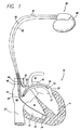
- FIG. 1 it illustrates a heart 10 in need of cardiac rhythm management and atrial fibrillation prevention pacing shown in association with an implantable medical device 30 embodying the present invention.
- the portions of the heart 10 illustrated in FIG. 1 are the right ventricle 12, the left ventricle 14, the right atrium 16 , and the left atrium 18. Also illustrated are the superior vena cava 20 , the coronary sinus 22 , the os or opening to the coronary sinus 24 , and the great cardiac vein 25.
- the implantable medical device 30 is arranged to be implanted in an upper left chest portion of a patient within a subcutaneous pocket.
- the implantable medical device 30 includes a first endocardial lead 32 having an electrode pair including a distal electrode 34 and a proximal electrode 36.
- the electrodes 34 and 36 are disposed or implanted in the right ventricle 12 to permit the sensing of ventricular activity and the application of pacing pulses to the right ventricle.
- the implantable medical device 30 further includes a second endocardial lead 42 having an electrode pair including a distal electrode 44 and a proximal electrode 46.
- the electrodes 44 and 46 are disposed or implanted in the right atrium 16 of the heart 10 to permit sensing of right atrial activity and the application of pacing pulses to the right atrium.
- the implantable medical device 30 still further includes an intravascular lead 52 having an electrode pair including a distal electrode 54 and a proximal electrode 56.
- the electrodes 54 and 56 are disposed or implanted in the coronary sinus vein 25 of the heart 10 adjacent the left atrium 18.
- the electrodes 54 and 56 permit sensing of left atrial activity and the application of pacing pulses to the left atrium 18.
- one of electrodes 54 and 56 may be utilized with one of electrodes 44 and 46 for broad field sensing of atrial activity to eliminate restrictions of a very narrow view of electrical activity of the atria.
- electrodes 44 and 46 may be placed in parallel and used for sensing atrial activity (with the conductive enclosure 40 of the implantable medical device 30 as the reference) to provide an alternate approach for broad field sensing of atrial activity of the heart 10.
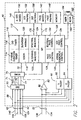
- the implantable medical device 30 includes within the enclosure 40 an atrial activity sensing system 50 , a digitizing multiplexer 70 , a ventricular sense amplifier 80 , a pulse generator circuit 90 , and a microprocessor 110 .
- the implantable medical device 30 further includes a memory 140 and a telemetry circuit 160.
- the atrial activity sensing system 50 detects atrial activity of the heart 10 .
- the atrial activity sensing system 50 includes sense amplifiers 60, 62, 64, and 66 .
- Sense amplifier 60 has an input which is coupled to the conductive enclosure 40 of the implantable medical device 30 by a line 58 .
- the other input of the sense amplifier 60 is resistively coupled to both electrodes 46 and 44 of lead 42 by conductors 146 and 144 respectively of lead 42.
- the output of sense amplifier 60 is coupled to a bandpass filter 61 having an output 71 .
- Sense amplifier 62 has an input coupled to electrode 46 by the conductor 146 of lead 42 and another input coupled to electrode 44 of lead 42 the conductor 144 of lead 42.
- the output of sense amplifier 62 is coupled to a bandpass filter 63 having an output 73.
- the output 73 provides a signal representing atrial activity of the right atrium which is sensed in the right atrium in a differential mode. This provides a crisp identification of P-waves of the detected atrial activity by responding to the "local" higher frequency content of the signal.
- Sense amplifier 66 has an input which is coupled to electrode 56 of lead 52 by a conductor 156 of lead 52 and another input coupled to electrode 54 by another conductor 154 of lead 52.
- the output of sense amplifier 66 is coupled to a bandpass filter 67 having an output 77 which provides a signal representing atrial activity of the left atrium.
- the atrial activity sensed by electrodes 54 and 56 is sensed locally and differentially to provide crisp indications of P-waves of the left atrium.
- sense amplifier 64 has an input which is coupled to electrode 44 of lead 42 by conductor 144 and another input coupled to the electrode 56 of lead 52 by conductor 156.
- the output of sense amplifier 64 is coupled to a bandpass filter 65 having an output 75 which provides a signal representing atrial activity sensed between electrode 56 of lead 52 and electrode 44 of lead 42. This provides an alternative approach to sensing of atrial activity.
- Each of the outputs 71, 73,75, and 77 of the atrial activity sensing system 50 is coupled to an input of the digitizing multiplexer 70.
- the digitizing multiplexer selects selected ones of the atrial activity sensing system outputs for use in determining when atrial fibrillation prevention pacing is required.
- the pulse generator 90 provides pacing pulses to the heart under control of the microprocessor 110. It thus provides pacing to the heart to provide regular pacing therapy and in addition, in accordance with the present invention, atrial fibrillation prevention pacing therapy as well.
- the pulse generator 90 includes a ventricular pulse generator 92 having outputs coupled to electrodes 36 and 34 of lead 32 by conductors 136 and 134 of lead 32. This enables the ventricular pulse generator 92 to apply pacing pulses to the right ventricle.
- the pulse generator 90 further includes an atrial pulse generator 94 having a first pair of outputs coupled to electrodes 44 and 46 of lead 42 by the conductors 144 and 146 of lead 42.
- the atrial pulse generator 94 includes a second pair of outputs coupled to electrodes 56 and 54 of lead 52 by conductors 156 and 154 of lead 52. While the ventricular pulse generator 92 and the atrial pulse generator 94 are shown configured to generate pacing pulses in a bipolar fashion, this is for illustration purposes only and one of skill in the art could readily adapt the pulse generators 92 and 94 to selectively switch in the conductive enclosure 40 as a reference electrode in place of the electrodes 36, 46 , and 56 to provide unipolar pacing pulses in a respective chamber of the heart.
- unipolar atrial, biatrial and ventricular stimulation are within the spirit of the invention.
- This enables the atrial pulse generator 94 to apply pacing pulses to either the right atrium or the left atrium or simultaneously to both atria.
- the atrial fibrillation prevention pacing modalities which may be employed in accordance with the preferred embodiments of the present invention will be described subsequently.
- the microprocessor 110 controls the overall functioning of the implantable medical device 30. To implement such control, the microprocessor executes operating instructions stored in the memory 140 and utilizes various parameters also stored in memory 140. For example, the memory 140 stores, in a storage location 142, the operating instructions defining the various pacing modalities, including the atrial arrhythmia prevention modalities including atrial fibrillation prevention pacing modalities in accordance with the present invention, which may be provided by the implantable medical device 30. Pacing parameters may be stored in a storage location 148.
- operating instructions defining atrial detection modalities are stored in storage location 150
- atrial detection parameters are stored in memory location 152
- detection criterion are stored in memory location 158.
- the microprocessor 110 is coupled to the memory 140 by a multiple-bit address bus 170 and a bi-directional, multiple-bit data bus 172.
- the microprocessor 140 uses the address bus 170 to fetch operating instructions or parameters from the memory at address locations defined on the address bus 170.
- the fetched instructions and parameters are conveyed to the microprocessor 140 over the data bus 172.
- the microprocessor 110 may store data in the memory 140 at memory locations defined on the address bus 170.
- the microprocessor 110 conveys the data to the memory over the data bus 172.
- Such microprocessor and memory operation are conventional in the art.
- the microprocessor 110 When executing the operating instructions stored in the memory 140, the microprocessor 110 implements a number of functional stages in accordance with the present invention.
- the functional stages are divided into a first group 112 for determining when detected atrial activity satisfies a predetermined criterion to require atrial fibrillation prevention pacing, and a second group 126 which controls the provision of the atrial fibrillation prevention pacing.
- the first group of functional stages includes a P-wave duration timer 114, an interatrial delay timer 116, a discriminator stage 118 , a P-wave duration averaging stage 120 , an altemans analysis stage 122, and a spectral analysis stage 124.
- the second group of stages 126 includes a pace site control stage 128, an atrial overdrive control stage 130, a biatrial pace control stage 132, and a DDT pace control stage 134.
- the implantable medical device 30 determines that the heart 10 is in need of atrial fibrillation prevention pacing based upon P-wave duration. More particularly, if a P-wave of a cardiac cycle is longer than, for example, 140 milliseconds, indicative of an interatrial conduction disturbance, the discriminator stage 118 will cause the heart to be paced in one of the atrial fibrillation prevention pacing modalities to be described hereinafter.
- the microprocessor during regular pacing by the implantable medical device 30 required for the patient and programmed by the physician, measures the duration of the P-waves occurring during each cardiac cycle.
- the microprocessor from an output 72 of the digitizing multiplexer, monitors the digitized electrograms resulting from the electrogram provided by the atrial activity sensing system 50 at its output 73.
- the electrogram thus monitored for this purpose is the electrogram resulting from the sensing of atrial activity in the right atrium by the electrode pair 44 and 46.
- the selected characteristic of the detected atrial activity for determining the presence of interatrial conduction disturbance and the need of atrial fibrillation prevention pacing may be averaged P-wave duration.
- the microprocessor 112 may cause the digitizing multiplexer 70 to digitize the electrograms occurring at outputs 71 and 73 of the atrial activity sensing system 50 .
- the digitized electrogram of output 71 would in this case be a broad field sensed electrogram sensed between the parallel combination of electrodes 44 and 46 and the conductive enclosure 40 of the implantable medical device 30.
- the broad field electrograms may be stored in the memory 140 and the electrogram derived from output 73 may be utilized to line up the detected P-waves to permit the duration average stage 120 to conduct a point-by-point average.
- the discriminator 118 will then determine if the averaged P-wave duration satisfies a predetermined criterion.
- the predetermined criterion may be an averaged P-wave duration greater than 140 milliseconds.
- the discriminator stage 118 will then cause the second group of functional stages 126 to provide the heart with atrial fibrillation prevention pacing pulses in accordance with a selected atrial fibrillation prevention pacing modality.
- the far-field P-waves to be averaged may be derived from output 75 of the atrial activity sensing system 50.
- This atrial activity electrogram results from the sensing of atrial activity between electrode 56 in the great cardiac vein and electrode 44 in the right atrium.
- This will also provide a far-field atrial electrogram for providing the P-waves to be averaged by the duration average stage 120 .
- the atrial electrogram from output 73 may be utilized to line up the P-waves to be averaged for data analysis.
- the bandpass filter 65 may be chosen to have a broad bandpass for detecting low frequency components of the atrial activity.
- a signal averaging technique based on, for example, 100 or 1000 cardiac cycles, ambient noise that would be otherwise detected may be eliminated.
- the selected characteristic of the detected atrial activity for detecting an interatrial conduction disturbance and the need for atrial fibrillation prevention pacing may be based upon P-wave altemans analysis.
- a predetermined characteristic of the odd and even P-waves may be averaged by the altemans analysis stage 122. If the average predetermined characteristic of the odd and even P-waves when compared by discriminating stage 118 satisfies a predetermined criterion, the discriminating stage 118 will cause the second group of functional stages 126 to provide the atrial fibrillation prevention pacing.
- theretemans characteristic to be monitored may be, for example, P-wave height, P-wave duration, or the area under the P-wave electrogram. If the averaged characteristic of the odd and even P-waves differ by, for example, more than two percent (2%), this will satisfy the predetermined criterion and thus cause the provision of the atrial fibrillation prevention pacing.
- the atrial electrograms which may be used for the altemans analysis may be derived from either output 73 of the atrial activity sensing system 50 or the output 77 of the atrial activity sensing system. Either output, by providing an electrogram detected locally within a selected one of the atria, will provide a suitable signal for the altemans analysis.
- the selected characteristic of the detected atrial activity for detecting an interatrial conduction disturbance and the need for atrial fibrillation prevention pacing may be interatrial delay.
- the microprocessor preferably monitors the digitized electrograms derived from outputs 73 and 77 of the atrial activity sensing system 50 .
- the interatrial delay timer 116 will detect when a P-wave occurs in the right atrium and the left atrium and measures the time between the beginning of P-waves in those two chambers. The time between the beginning of the same P-wave within the right atrium and the left atrium is the interatrial delay.
- the selected characteristic of the detected atrial activity for detecting an interatrial conduction disturbance and the need for atrial fibrillation prevention pacing may be spectral analysis of the P-waves.
- the spectral analysis stage 124 will monitor the digitized atrial electrograms derived from output 73 , for example, of the atrial activity sensing system 50 . It performs a spectral analysis of each P-wave. After spectral analysis, the discriminating stage 118 will analyze the spectrum analysis to determine if there has been a shift in the spectral energy distribution of each P-wave. If the discriminator 118 determines that there has been a shift to more energy in the higher frequency bands of a P-wave, it will then cause the second group of functional stages 126 to provide the atrial fibrillation prevention pacing.
- the atrial fibrillation prevention pacing may be atrial overdrive pacing or DDT pacing.
- the atrial overdrive control stage 130 causes the atrial pulse generator 94 to deliver pacing pulses to one or both of the atria at a rate which is faster than then intrinsic atrial rate of the heart.
- the atrial pulse generator may apply the overdrive atrial pacing pulses to the right atrial lead 42 , to left atrial lead 52, or to both leads simultaneously in either a unipolar or a bipolar fashion.
- a conventional DDT mode of pacing may be employed to control the interatrial conduction disturbance. For example, by sensing in the right atrium and directing the triggered pacing pulse to stimulate the left atrium, the device would effectively overdrive the left atrium and reduce the interatrial conduction disturbance.
- a modified DDT mode of pacing may be employed to control the interatrial conduction disturbance, wherein the time between the sensing of P-wave in the right atrium and the stimulation pluses (A-pulse) in the left atrium is programmable, i.e. , a programmable P-A delay.
- the duration of the P-wave may be a criterion for selecting the P-A delay, either by,the clinician or automatically by the implantable medical device. More specifically, the P-A delay may be varied inversely with the P-wave duration. Accordingly, this modification of the DDT mode could provide greater control for reducing the interatrial conduction disturbances.
- the atrium to be paced may be adjusted by the biatrial pace control 132 based upon the chamber in which the P-waves are initially detected. For example, if the P-waves are initially detected in the right atrium, the left atrium may be paced. If the P-waves are initially detected in the left atrium, the right atrium may be paced.
- the selected characteristic of the atrial activity used to determine the need for the atrial fibrillation prevention pacing therapy may be monitored. If the selected characteristic of the detected atrial activity satisfies a second predetermined criterion, the discriminating stage 118 will then terminate the atrial fibrillation prevention pacing therapy and return the device to its regular pacing modality since the interatrial conduction disturbance will have subsided or will have been terminated.
- the atrial fibrillation prevention pacing may allow periodic pauses in the pacing rate to permit measurement of intrinsic P-waves to determined if the atrial fibrillation prevention pacing should be terminated, using as a criterion of, for example, a P-wave duration below 130 ms.
- the second predetermined criterion may be the same as the first predetermined criterion for determining the need for atrial fibrillation prevention pacing, or it could be a different criterion as in the example above.
Landscapes
- Health & Medical Sciences (AREA)
- Cardiology (AREA)
- Heart & Thoracic Surgery (AREA)
- Engineering & Computer Science (AREA)
- Biomedical Technology (AREA)
- Nuclear Medicine, Radiotherapy & Molecular Imaging (AREA)
- Radiology & Medical Imaging (AREA)
- Life Sciences & Earth Sciences (AREA)
- Animal Behavior & Ethology (AREA)
- General Health & Medical Sciences (AREA)
- Public Health (AREA)
- Veterinary Medicine (AREA)
- Electrotherapy Devices (AREA)
Applications Claiming Priority (2)
| Application Number | Priority Date | Filing Date | Title |
|---|---|---|---|
| US09/338,216 US6292694B1 (en) | 1999-06-22 | 1999-06-22 | Implantable medical device having atrial tachyarrhythmia prevention therapy |
| US338216 | 1999-06-22 |
Publications (3)
| Publication Number | Publication Date |
|---|---|
| EP1062987A2 true EP1062987A2 (de) | 2000-12-27 |
| EP1062987A3 EP1062987A3 (de) | 2003-07-23 |
| EP1062987B1 EP1062987B1 (de) | 2009-05-27 |
Family
ID=23323905
Family Applications (1)
| Application Number | Title | Priority Date | Filing Date |
|---|---|---|---|
| EP00305271A Expired - Lifetime EP1062987B1 (de) | 1999-06-22 | 2000-06-22 | Implantierbare medizinische Vorrichtung |
Country Status (3)
| Country | Link |
|---|---|
| US (2) | US6292694B1 (de) |
| EP (1) | EP1062987B1 (de) |
| DE (1) | DE60042252D1 (de) |
Cited By (5)
| Publication number | Priority date | Publication date | Assignee | Title |
|---|---|---|---|---|
| WO2005013818A1 (en) | 2003-07-31 | 2005-02-17 | Medtronic, Inc. | Monitoring p-waves to detect degradation of atrial myocardium |
| US7027861B2 (en) * | 2001-10-09 | 2006-04-11 | Medtronic, Inc. | Method and apparatus for affecting atrial defibrillation with bi-atrial pacing |
| US7050852B2 (en) * | 2001-09-24 | 2006-05-23 | Cardiac Pacemakers, Inc. | Pacemaker mode switching based upon atrial conduction time |
| WO2007079343A3 (en) * | 2005-12-30 | 2007-09-27 | Medtronic Inc | Closed loop optimization of a-v and v-v timing |
| US7877144B2 (en) | 2006-07-26 | 2011-01-25 | Medtronic, Inc. | Predicting chronic optimal A-V intervals for biventricular pacing via observed inter-atrial delay |
Families Citing this family (25)
| Publication number | Priority date | Publication date | Assignee | Title |
|---|---|---|---|---|
| US6430438B1 (en) * | 1999-05-21 | 2002-08-06 | Cardiac Pacemakers, Inc. | Cardiac rhythm management system with atrial shock timing optimization |
| US8064997B2 (en) | 1999-05-21 | 2011-11-22 | Cardiac Pacemakers, Inc. | Method and apparatus for treating irregular ventricular contractions such as during atrial arrhythmia |
| US7039461B1 (en) | 2000-05-13 | 2006-05-02 | Cardiac Pacemakers, Inc. | Cardiac pacing system for prevention of ventricular fibrillation and ventricular tachycardia episode |
| US6622042B1 (en) * | 2001-05-09 | 2003-09-16 | Pacesetter, Inc. | Implantable cardiac stimulation device and method utilizing electrogram spectral analysis for therapy administration |
| US6973349B2 (en) | 2001-12-05 | 2005-12-06 | Cardiac Pacemakers, Inc. | Method and apparatus for minimizing post-infarct ventricular remodeling |
| US6957104B2 (en) * | 2002-01-03 | 2005-10-18 | Cardiac Pacemakers, Inc. | Ventricular pacing for prevention of atrial fibrillation |
| US6957105B2 (en) | 2002-03-26 | 2005-10-18 | Cardiac Pacemakers, Inc. | Method and apparatus for detecting oscillations in cardiac rhythm with electrogram signals |
| US7039462B2 (en) * | 2002-06-14 | 2006-05-02 | Cardiac Pacemakers, Inc. | Method and apparatus for detecting oscillations in cardiac rhythm |
| US7113825B2 (en) | 2002-05-03 | 2006-09-26 | Cardiac Pacemakers, Inc. | Method and apparatus for detecting acoustic oscillations in cardiac rhythm |
| US6965797B2 (en) * | 2002-09-13 | 2005-11-15 | Cardiac Pacemakers, Inc. | Method and apparatus for assessing and treating myocardial wall stress |
| US7321794B2 (en) * | 2002-11-15 | 2008-01-22 | Advanced Bionics Corporation | Method and system for treating atrial fibrillation |
| US7328066B1 (en) | 2003-03-28 | 2008-02-05 | Pacesetter, Inc. | Implantable cardiac stimulation device, system and method that identifies and prevents impending arrhythmias of the atria |
| US7164944B1 (en) | 2003-04-15 | 2007-01-16 | Pacesetter, Inc. | Analgesic therapy for ICD patients |
| US20050245975A1 (en) * | 2004-04-15 | 2005-11-03 | Hettrick Douglas A | Method and apparatus for controlling delivery of pacing pulses in response to increased ectopic frequency |
| US8233978B1 (en) | 2004-07-12 | 2012-07-31 | Pacesetter, Inc. | Method and device for switching between arrhythmia prevention modes |
| US7590445B1 (en) | 2005-02-01 | 2009-09-15 | Pacesetter, Inc. | Indirect mechanical medical therapy system |
| US8700155B2 (en) * | 2005-03-31 | 2014-04-15 | Medtronic, Inc. | System and method for using atrial pacing to enhance function of stunned atrial myocardium following conversion to normal sinus rhythm |
| US7551961B1 (en) * | 2006-04-10 | 2009-06-23 | Pacesetter, Inc. | Cardiac stimulation device with selective atrial pacing on premature ventricular complex detection and method |
| US7756577B1 (en) | 2006-04-21 | 2010-07-13 | Pacesetter, Inc. | Multi-modal medical therapy system |
| US8437850B2 (en) * | 2006-05-18 | 2013-05-07 | Medtronic, Inc. | Automatic enabling of post long pause overdrive pacing |
| US8521277B2 (en) * | 2008-09-04 | 2013-08-27 | Pacesetter, Inc. | Implantable systems and method for use therewith for tracking changes in hemodynamics and cardiac disease |
| US9533158B2 (en) * | 2008-12-11 | 2017-01-03 | Pacesetter, Inc. | System and method for monitoring patient condition using atrial timing characteristics |
| DE102009002988A1 (de) * | 2009-05-11 | 2010-11-25 | Biotronik Crm Patent Ag | Implantierbarer P-Wellen-Dispersionsdetektor |
| US20110048429A1 (en) * | 2009-09-02 | 2011-03-03 | Tyco Healthcare Group Lp | Patient Positioning Apparatus |
| US10780288B2 (en) | 2017-12-19 | 2020-09-22 | Pacesetter, Inc. | Systems amd methods for suppressing and treating atrial fibrillation and atrial tachycardia |
Family Cites Families (9)
| Publication number | Priority date | Publication date | Assignee | Title |
|---|---|---|---|---|
| US5042497A (en) * | 1990-01-30 | 1991-08-27 | Cardiac Pacemakers, Inc. | Arrhythmia prediction and prevention for implanted devices |
| US5514164A (en) * | 1994-03-25 | 1996-05-07 | Pacesetter, Inc. | DDD pacing response to atrial tachyucardia and retrograde conduction |
| FR2718036B1 (fr) * | 1994-04-05 | 1996-08-30 | Ela Medical Sa | Procédé de commande d'un stimulateur cardiaque auriculaire double du type triple chambre. |
| US5562708A (en) * | 1994-04-21 | 1996-10-08 | Medtronic, Inc. | Method and apparatus for treatment of atrial fibrillation |
| US5609158A (en) | 1995-05-01 | 1997-03-11 | Arrhythmia Research Technology, Inc. | Apparatus and method for predicting cardiac arrhythmia by detection of micropotentials and analysis of all ECG segments and intervals |
| DE69631568T2 (de) * | 1995-07-25 | 2004-12-16 | Ela Medical S.A. | Zweikammer-Herzschrittmacher |
| US6058328A (en) * | 1996-08-06 | 2000-05-02 | Pacesetter, Inc. | Implantable stimulation device having means for operating in a preemptive pacing mode to prevent tachyarrhythmias and method thereof |
| US5840038A (en) | 1997-05-29 | 1998-11-24 | Marquette Medical Systems, Inc. | Method and apparatus for signal averaging and analyzing high resolution P wave signals from an electrocardiogram |
| US5902324A (en) * | 1998-04-28 | 1999-05-11 | Medtronic, Inc. | Bi-atrial and/or bi-ventricular sequential cardiac pacing systems |
-
1999
- 1999-06-22 US US09/338,216 patent/US6292694B1/en not_active Expired - Lifetime
-
2000
- 2000-06-22 EP EP00305271A patent/EP1062987B1/de not_active Expired - Lifetime
- 2000-06-22 DE DE60042252T patent/DE60042252D1/de not_active Expired - Lifetime
-
2001
- 2001-08-15 US US09/931,481 patent/US7010346B1/en not_active Expired - Fee Related
Non-Patent Citations (1)
| Title |
|---|
| None |
Cited By (9)
| Publication number | Priority date | Publication date | Assignee | Title |
|---|---|---|---|---|
| US7050852B2 (en) * | 2001-09-24 | 2006-05-23 | Cardiac Pacemakers, Inc. | Pacemaker mode switching based upon atrial conduction time |
| US7027861B2 (en) * | 2001-10-09 | 2006-04-11 | Medtronic, Inc. | Method and apparatus for affecting atrial defibrillation with bi-atrial pacing |
| WO2005013818A1 (en) | 2003-07-31 | 2005-02-17 | Medtronic, Inc. | Monitoring p-waves to detect degradation of atrial myocardium |
| JP2007500533A (ja) * | 2003-07-31 | 2007-01-18 | メドトロニック・インコーポレーテッド | 心房心筋層の機能低下を検出するためのp波の監視 |
| US7620446B2 (en) | 2003-07-31 | 2009-11-17 | Medtronic, Inc. | Monitoring P-waves to detect degradation of atrial myocardium |
| JP4921166B2 (ja) * | 2003-07-31 | 2012-04-25 | メドトロニック,インコーポレイテッド | 心房心筋層の機能低下を検出するためのp波の監視 |
| WO2007079343A3 (en) * | 2005-12-30 | 2007-09-27 | Medtronic Inc | Closed loop optimization of a-v and v-v timing |
| US7848807B2 (en) | 2005-12-30 | 2010-12-07 | Medtronic, Inc. | Closed loop optimization of A-V and V-V timing |
| US7877144B2 (en) | 2006-07-26 | 2011-01-25 | Medtronic, Inc. | Predicting chronic optimal A-V intervals for biventricular pacing via observed inter-atrial delay |
Also Published As
| Publication number | Publication date |
|---|---|
| US6292694B1 (en) | 2001-09-18 |
| DE60042252D1 (de) | 2009-07-09 |
| US7010346B1 (en) | 2006-03-07 |
| EP1062987A3 (de) | 2003-07-23 |
| EP1062987B1 (de) | 2009-05-27 |
Similar Documents
| Publication | Publication Date | Title |
|---|---|---|
| US6292694B1 (en) | Implantable medical device having atrial tachyarrhythmia prevention therapy | |
| CN107249437B (zh) | 用于房性心律失常事件检测的方法和装置 | |
| US5817134A (en) | Apparatus and method for detecting atrial fibrillation by morphological analysis | |
| US7558626B2 (en) | Cardiac resynchronization via left ventricular pacing | |
| US7415307B2 (en) | Ischemia detection based on cardiac conduction time | |
| US7130681B2 (en) | Use of accelerometer signal to augment ventricular arrhythmia detection | |
| JP4249017B2 (ja) | 遠方場r波をフィルタリングするための複数のテンプレート | |
| EP1677673B1 (de) | Verfahren und gerät zum nachweis und zur diskriminierung von arrhythmien | |
| EP2242538B1 (de) | Verfahren zur überwachung eines hämodynamischen status für herzrhythmusunterscheidungen | |
| US8768459B2 (en) | Morphology-based precursor to template matching comparison | |
| US20100114222A1 (en) | Lead integrity testing triggered by sensed asystole | |
| JP2002519131A (ja) | 心房検知のみを用いて心臓の心房イベントを検出するシステムおよび方法 | |
| EP2237722B1 (de) | Gerät zur überwachung von t-wellen-alternans | |
| EP2371280B1 (de) | Arrhythmieklassifizierung | |
| US9119545B2 (en) | Arrhythmia classification | |
| WO2008042684A2 (en) | Method and apparatus for assessing induced t-wave alternans | |
| US7149569B1 (en) | Apparatus and method for improved morphology discrimination in an implantable cardioverter defibrillator | |
| JP2005504569A (ja) | 心臓信号を監視する埋め込み可能医療装置 |
Legal Events
| Date | Code | Title | Description |
|---|---|---|---|
| PUAI | Public reference made under article 153(3) epc to a published international application that has entered the european phase |
Free format text: ORIGINAL CODE: 0009012 |
|
| AK | Designated contracting states |
Kind code of ref document: A2 Designated state(s): AT BE CH CY DE DK ES FI FR GB GR IE IT LI LU MC NL PT SE |
|
| AX | Request for extension of the european patent |
Free format text: AL;LT;LV;MK;RO;SI |
|
| PUAL | Search report despatched |
Free format text: ORIGINAL CODE: 0009013 |
|
| AK | Designated contracting states |
Designated state(s): AT BE CH CY DE DK ES FI FR GB GR IE IT LI LU MC NL PT SE |
|
| AX | Request for extension of the european patent |
Extension state: AL LT LV MK RO SI |
|
| 17P | Request for examination filed |
Effective date: 20040115 |
|
| AKX | Designation fees paid |
Designated state(s): CH DE FR IE IT LI |
|
| 17Q | First examination report despatched |
Effective date: 20061221 |
|
| GRAP | Despatch of communication of intention to grant a patent |
Free format text: ORIGINAL CODE: EPIDOSNIGR1 |
|
| RIC1 | Information provided on ipc code assigned before grant |
Ipc: A61N 1/362 20060101AFI20081106BHEP |
|
| GRAS | Grant fee paid |
Free format text: ORIGINAL CODE: EPIDOSNIGR3 |
|
| GRAA | (expected) grant |
Free format text: ORIGINAL CODE: 0009210 |
|
| AK | Designated contracting states |
Kind code of ref document: B1 Designated state(s): CH DE FR IE IT LI |
|
| REG | Reference to a national code |
Ref country code: CH Ref legal event code: NV Representative=s name: KIRKER & CIE S.A. Ref country code: CH Ref legal event code: EP |
|
| REG | Reference to a national code |
Ref country code: IE Ref legal event code: FG4D |
|
| REF | Corresponds to: |
Ref document number: 60042252 Country of ref document: DE Date of ref document: 20090709 Kind code of ref document: P |
|
| PLBE | No opposition filed within time limit |
Free format text: ORIGINAL CODE: 0009261 |
|
| STAA | Information on the status of an ep patent application or granted ep patent |
Free format text: STATUS: NO OPPOSITION FILED WITHIN TIME LIMIT |
|
| PG25 | Lapsed in a contracting state [announced via postgrant information from national office to epo] |
Ref country code: IE Free format text: LAPSE BECAUSE OF NON-PAYMENT OF DUE FEES Effective date: 20090622 |
|
| 26N | No opposition filed |
Effective date: 20100302 |
|
| PGFP | Annual fee paid to national office [announced via postgrant information from national office to epo] |
Ref country code: CH Payment date: 20120625 Year of fee payment: 13 |
|
| PGFP | Annual fee paid to national office [announced via postgrant information from national office to epo] |
Ref country code: FR Payment date: 20120705 Year of fee payment: 13 |
|
| PGFP | Annual fee paid to national office [announced via postgrant information from national office to epo] |
Ref country code: IT Payment date: 20120622 Year of fee payment: 13 |
|
| PGFP | Annual fee paid to national office [announced via postgrant information from national office to epo] |
Ref country code: DE Payment date: 20130627 Year of fee payment: 14 |
|
| REG | Reference to a national code |
Ref country code: CH Ref legal event code: PL |
|
| REG | Reference to a national code |
Ref country code: FR Ref legal event code: ST Effective date: 20140228 |
|
| PG25 | Lapsed in a contracting state [announced via postgrant information from national office to epo] |
Ref country code: LI Free format text: LAPSE BECAUSE OF NON-PAYMENT OF DUE FEES Effective date: 20130630 Ref country code: CH Free format text: LAPSE BECAUSE OF NON-PAYMENT OF DUE FEES Effective date: 20130630 |
|
| PG25 | Lapsed in a contracting state [announced via postgrant information from national office to epo] |
Ref country code: FR Free format text: LAPSE BECAUSE OF NON-PAYMENT OF DUE FEES Effective date: 20130701 Ref country code: IT Free format text: LAPSE BECAUSE OF NON-PAYMENT OF DUE FEES Effective date: 20130622 |
|
| REG | Reference to a national code |
Ref country code: DE Ref legal event code: R119 Ref document number: 60042252 Country of ref document: DE |
|
| REG | Reference to a national code |
Ref country code: DE Ref legal event code: R119 Ref document number: 60042252 Country of ref document: DE Effective date: 20150101 |
|
| PG25 | Lapsed in a contracting state [announced via postgrant information from national office to epo] |
Ref country code: DE Free format text: LAPSE BECAUSE OF NON-PAYMENT OF DUE FEES Effective date: 20150101 |