EP1062997B1 - Dispositif pour la séparation de particules solides de l'air sur des filtres à manche - Google Patents
Dispositif pour la séparation de particules solides de l'air sur des filtres à manche Download PDFInfo
- Publication number
- EP1062997B1 EP1062997B1 EP00110923A EP00110923A EP1062997B1 EP 1062997 B1 EP1062997 B1 EP 1062997B1 EP 00110923 A EP00110923 A EP 00110923A EP 00110923 A EP00110923 A EP 00110923A EP 1062997 B1 EP1062997 B1 EP 1062997B1
- Authority
- EP
- European Patent Office
- Prior art keywords
- collar
- tube plate
- cage frame
- prominences
- sleeve filter
- Prior art date
- Legal status (The legal status is an assumption and is not a legal conclusion. Google has not performed a legal analysis and makes no representation as to the accuracy of the status listed.)
- Expired - Lifetime
Links
- 239000002245 particle Substances 0.000 title claims abstract description 5
- 239000007787 solid Substances 0.000 title claims abstract description 5
- 238000000926 separation method Methods 0.000 title 1
- 238000001914 filtration Methods 0.000 claims abstract description 11
- 210000001364 upper extremity Anatomy 0.000 claims abstract description 4
- 210000003414 extremity Anatomy 0.000 claims description 11
- 239000002184 metal Substances 0.000 claims description 9
- 238000003780 insertion Methods 0.000 claims description 6
- 230000037431 insertion Effects 0.000 claims description 6
- 239000000463 material Substances 0.000 claims description 5
- 238000012423 maintenance Methods 0.000 description 2
- 229910000831 Steel Inorganic materials 0.000 description 1
- 230000015572 biosynthetic process Effects 0.000 description 1
- 239000004744 fabric Substances 0.000 description 1
- 238000000034 method Methods 0.000 description 1
- 230000037361 pathway Effects 0.000 description 1
- 230000000284 resting effect Effects 0.000 description 1
- 239000011343 solid material Substances 0.000 description 1
- 239000010959 steel Substances 0.000 description 1
- 238000006467 substitution reaction Methods 0.000 description 1
- 238000003466 welding Methods 0.000 description 1
Images


Classifications
-
- B—PERFORMING OPERATIONS; TRANSPORTING
- B01—PHYSICAL OR CHEMICAL PROCESSES OR APPARATUS IN GENERAL
- B01D—SEPARATION
- B01D46/00—Filters or filtering processes specially modified for separating dispersed particles from gases or vapours
- B01D46/02—Particle separators, e.g. dust precipitators, having hollow filters made of flexible material
- B01D46/06—Particle separators, e.g. dust precipitators, having hollow filters made of flexible material with means keeping the working surfaces flat
-
- B—PERFORMING OPERATIONS; TRANSPORTING
- B01—PHYSICAL OR CHEMICAL PROCESSES OR APPARATUS IN GENERAL
- B01D—SEPARATION
- B01D2265/00—Casings, housings or mounting for filters specially adapted for separating dispersed particles from gases or vapours
- B01D2265/06—Details of supporting structures for filtering material, e.g. cores
-
- B—PERFORMING OPERATIONS; TRANSPORTING
- B01—PHYSICAL OR CHEMICAL PROCESSES OR APPARATUS IN GENERAL
- B01D—SEPARATION
- B01D2271/00—Sealings for filters specially adapted for separating dispersed particles from gases or vapours
- B01D2271/02—Gaskets, sealings
Definitions
- the present invention relates to an apparatus for separating solid materials from air by means of filtering and, in particular, relates to filtering devices that use sleeve filters.
- the air to be filtered is made to pass by aspiration through the surface of tubular elements called sleeve filters which are made of a fabric filtering material and are closed at one extremity, so that the solid particles are deposited on the external walls of said sleeves.
- the system of fixing the sleeve filter and the cage frame to the tube plate requires particular care in as far as it must, on the one hand, guarantee an airtight seal and prevent the formation of preferential pathways for air to pass without being filtered and, on the other, allow rapid dismantling of the system for routine maintenance or substitution of the sleeve filters in the case of wearing-out or breakup of the same sleeve.
- the sleeve filter and the cage frame are generally fixed to the tube plate by a locking means comprising clips and bolts that acts on the reverse edge of the open extremity of the sleeve filter and on the edge or flange of the cage frame.
- sleeve filters have been proposed whose open extremity presents a thickened edge or cuff.
- the flange of the cage frame is substantially semicircular in section, and adheres to the cuff surface of the sleeve filter.
- a system for fixing the sleeve filter to the tube plate has been proposed recently that does not use clips and bolts, but provides for the use of an elastic ring (snap ring), normally made of steel, inserted inside the edge of the open extremity of the sleeve filter, for instance by means of stitching.
- the diameter of the ring is substantially equal to that of the opening in the tube plate and there is a groove along the entire external circumference of the ring equal to the thickness of the tube plate.
- the latter reasserts its shape and compresses the sleeve against the edge of the opening.
- FIG. 1 An example of this system is described and illustrated in the German Model G 80 03 027.9.
- Said publication shows a filtering device comprising a sleeve filter and an anti-collapse cage frame inserted thereto, said cage frame being substantially constituted by a flanged cylindrical body provided on its external surface with a circumferential relief protruding from said external surface in correspondence of the lower surface of a metal plate provided with an opening in which said filter device is inserted, passing from the upper surface to the lower one.
- said relief is able to make a seal airtight between the sleeve filter and the plate by locking said filter against the lower edge of said opening.
- the body is circumferentially interrupted in order to consent a lowering of its diameter to pass through the plate opening whereas a ring inserted in the upper portion of the body, when the filter is in operating position, maintains said upper portion of the body to its maximum diameter and compress the corresponding portion of the sleeve filter against the edge of said opening on the plate, avoiding any unwanted sliding of the body out of the plate opening.
- the present state of the art does not provide filtering devices with sleeve filters and anti-collapse or cage frames in which said cage frames and sleeve filters guarantee perfect fixing of the cage frame and at the same time can be fitted and fixed onto tube plates without recourse to locking systems of flanges, clips and bolts.
- the purpose of the present invention is to propose a device for filtering air in order to remove solid particles therein contained, of the sleeve filter type, in which the seal between the sleeve filter and the tube plate into which the sleeve filter is inserted is achieved without recourse to locking or fixing systems constituted by clips or flanges and bolts, but still guarantees perfect attachment of the anti-collapse or cage frame arranged inside the sleeve filter.
- a second purpose of the present invention is to propose an anti-collapse or cage frame to be used in the filtering device referred to above.
- the purposes of the present invention are achieved by using a cage frame that presents at least one series of elastic prominences in the upper cylindrical part, disposed substantially equidistant from the upper extremity of the cage frame; said series of elastic prominences, by means of the locking of the same against the lower edge of the opening of the plate, compress the sleeve filter against the edge of the tube plate thus making the seal airtight and locking the cage frame.
- the number of elastic prominences that constitute the series of elastic prominences is at least equal to two and preferably more than three.
- the locking of the elastic prominences against the lower edge of the opening of the tube plate can be achieved by means of the elastic return of the prominence after deformation due to the insertion of the cage frame and of the sleeve filter into the opening in the tube plate.
- the locking of the elastic prominences against the lower edge of the opening of the tube plate is preferably achieved using a rigid body sliding along the inside upper surface of the cage frame opposite that surface in contact with the sleeve filter, which pushes the prominences of the cage frame compressing the sleeve filter against the edge of the tube plate and maintains it locked in said position.
- the upper part of the anti-collapse or cage frame of the sleeve filter that presents the prominences could be constituted by a metal wire structure like the rest of the cage frame, or, preferably could be achieved with a rolled sheet metal cylinder and be connected with the lower part, also cylindrical but presenting large areas of empty space to allow the passage of the air through the sleeve filter.
- the prominences on the upper part of the cage frame could take any shape and could constitute one series or more than one series, said series could cooperate with one or more than one. Said prominences could be achieved by cutting into the material that constitutes the upper part of the cage frame or by attachments to said upper parts by means of welding or other known systems.
- the cage frame presents a first series of prominences that begin substantially at the level of the open extremity of the same and reach their maximum after a distance substantially equal to the thickness of the tube plate so that the tube plate could be locked between the flanged extremity of the cage frame and the portion of surface after the prominence.
- the locking is constituted by the edge of the tube plate.
- the rigid element that is made to slide inside the upper part of the cage frame is constituted by a rigid body, i.e. with greater resistance to deformation than the material of the prominences provided in the upper portion of the cage frame.
- the length of the rigid element is at least equal to the thickness of the tube plate. Preferably, said length is at least two or three times the thickness of the tube plate. Furthermore, it is advantageous that the upper part of said rigid cylindrical element ends in a flanged edge that facilitates the assembly of the cage frame and the sleeve filter into the opening of the tube plate.
- the rigid element could be constituted by rings rigidly interconnected by means of rods welded inside each ring.
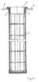
- Figure 1 is a front view, partially in section, of an anti-collapse or cage frame used in the present invention that presents the prominences in the upper part.
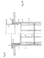
- Figure 2 shows the same cage frame of Figure 1 together with the sleeve filter fixed to the tube plate.
- Figures 3A and 3B show the assembly of the sleeve filter according to the invention.
- Figures 4A, 5A and 6A show three different profiles of the prominences on the upper part of the cage frames used according to the present invention, while Figures 4B, 5B and 6B respectively show the profiles that the upper parts of the cage frames assume after insertion into the tube plate.
- the cage frame 1 (indicated in its entirety) is constituted by vertical metal rods 2 fixed to spaced horizontal rings 3.
- the upper cage frame finishes in a collar 4 that presents one or more prominences 5 and a flange edge 6.
- the cage frame constitutes a support frame for the sleeve filter 7 ( Figure 2 ) that is fixed to the tube plate 8 by insertion of the rigid cylindrical element 9 inside the upper part of the cage frame 1.
- Figures 3A and 3B show schematically the procedure for inserting the rigid element for fixing the sleeve filter, in particular in Figure 3A the rigid element 9 in the course of its insertion into the collar 4 presses on the prominence 5 that, deforming, assumes the locked position against the lower edge of the opening of the tube plate as indicated in Figure 3B .
- Figures 4A, 5A and 6A show some profiles that the collars 4 of the cage frames could present together with the sleeve filter (not shown), in order to lock against the tube plate 8.
- Figures 4B, 5B and 6B show, respectively, the profiles of the cage frames locked against the tube plate.
Landscapes
- Chemical & Material Sciences (AREA)
- Chemical Kinetics & Catalysis (AREA)
- Filtering Of Dispersed Particles In Gases (AREA)
- Cyclones (AREA)
- Processing And Handling Of Plastics And Other Materials For Molding In General (AREA)
Claims (9)
- Dispositif de filtration pour filtrer l'air de manière à débarrasser les particules solides contenues dans celui-ci, comprenant une plaque porte-tube (8) et un filtre tubulaire (7) porté par une armature en cage anti-flambage (1), ladite armature en cage comprenant au niveau de son extrémité supérieure un collier à bride (4) pour forcer le filtre tubulaire contre la face supérieure du pourtour d'une ouverture dans ladite plaque porte-tube (8) dans laquelle ledit filtre tubulaire est introduit, caractérisé en ce que ledit collier (4) comporte au moins une série de saillies (5) déformables élastiquement découpées dans la matière dudit collier (4) à une certaine distance de ladite armature en cage anti-flambage (1), de sorte que, après insertion de ladite armature en cage et du filtre tubulaire dans ladite ouverture dans ladite plaque porte-tube (8), elles (5) forcent le filtre tubulaire (7) contre le bord de ladite ouverture et verrouillent celui-ci contre la face inférieure dudit pourtour de ladite ouverture dans la plaque porte-tube au moyen du retour élastique desdites saillies déformées en raison de ladite insertion de ladite armature en cage et du filtre tubulaire dans ladite ouverture.
- Dispositif selon la revendication 1, caractérisé en ce que ladite série de saillies (5) comprend au moins trois saillies.
- Dispositif selon la revendication 2, caractérisé en ce que ladite série de saillies (5) comprend un nombre égal de saillies diamétralement opposées.
- Dispositif selon la revendication 1, caractérisé en ce que lesdites saillies (5) commencent sensiblement au niveau de l'extrémité ouverte du collier et atteignent leur diamètre maximum après une distance sensiblement égale à l'épaisseur de la plaque porte-tube (8) de sorte que la plaque porte-tube puisse être verrouillée entre l'extrémité à bride du collier (4) et une partie de la surface de la saillie.
- Dispositif selon la revendication 1, caractérisé en ce que ledit collier (4) comprend une structure obtenue à partir d'une feuille de métal roulée pour former un cylindre.
- Dispositif selon la revendication 1, caractérisé en ce qu'il comprend un élément rigide (9) coulissant longitudinalement à l'intérieur du collier (4) sur la face supérieure opposée à la face en contact avec le filtre tubulaire (7), afin de pousser contre les saillies (5) du collier (4) de sorte à forcer le filtre tubulaire (7) contre le bord de la plaque porte-tube (8) et à le maintenir verrouillé dans cette position.
- Dispositif selon la revendication 6, caractérisé en ce que l'élément rigide (9) comprend un corps présentant une résistance à la déformation largement supérieure à celle des saillies (5) présentes dans la partie supérieure du collier.
- Dispositif selon la revendication 7, caractérisé en ce que l'élément rigide (9) est un cylindre ouvert aux deux extrémités, dont le diamètre est légèrement inférieur à celui de l'ouverture de la plaque porte-tube (8) dans laquelle le filtre tubulaire (7) doit être introduit et dont la longueur est égale à l'épaisseur de ladite plaque porte-tube.
- Armature en cage anti-flambage (1) prévue pour être utilisée dans le dispositif de filtration des revendications 1 à 8, comprenant un filtre tubulaire (7) et une armature en cage anti-flambage (1) introduite dans celui-ci, ladite armature en cage anti-flambage comprenant une structure inférieure en tiges métalliques et un collier supérieur (4), caractérisée en ce que le collier (4) est pourvu d'au moins une série de saillies (5) élastiquement déformables découpées dans la matière dudit collier (4) à une certaine distance du collier à bride au niveau de l'extrémité supérieure de l'armature en cage anti-flambage (1) et faisant saillie de la face externe dudit collier (4) afin d'assurer en utilisation une étanchéité à l'air du filtre tubulaire dans une ouverture d'une plaque filtrante.
Applications Claiming Priority (2)
| Application Number | Priority Date | Filing Date | Title |
|---|---|---|---|
| ITMI991183 | 1999-05-28 | ||
| IT1999MI001183A IT1312572B1 (it) | 1999-05-28 | 1999-05-28 | Dispositivo per la separazione di particelle solide a manichefiltranti. |
Publications (3)
| Publication Number | Publication Date |
|---|---|
| EP1062997A2 EP1062997A2 (fr) | 2000-12-27 |
| EP1062997A3 EP1062997A3 (fr) | 2001-03-14 |
| EP1062997B1 true EP1062997B1 (fr) | 2008-07-09 |
Family
ID=11383063
Family Applications (1)
| Application Number | Title | Priority Date | Filing Date |
|---|---|---|---|
| EP00110923A Expired - Lifetime EP1062997B1 (fr) | 1999-05-28 | 2000-05-24 | Dispositif pour la séparation de particules solides de l'air sur des filtres à manche |
Country Status (5)
| Country | Link |
|---|---|
| EP (1) | EP1062997B1 (fr) |
| AT (1) | ATE400346T1 (fr) |
| DE (1) | DE60039387D1 (fr) |
| ES (1) | ES2308956T3 (fr) |
| IT (1) | IT1312572B1 (fr) |
Families Citing this family (7)
| Publication number | Priority date | Publication date | Assignee | Title |
|---|---|---|---|---|
| US6858052B2 (en) | 2003-05-30 | 2005-02-22 | Bha Group, Inc. | Filter cartridge mounting structure |
| CN101396630B (zh) * | 2007-09-29 | 2011-03-23 | 天津市帅普环保科技企业孵化器有限公司 | 插接式除尘布袋框架 |
| US8337696B2 (en) * | 2010-01-28 | 2012-12-25 | Eaton Corporation | Method for making a bag filter housing |
| MX359078B (es) | 2012-01-05 | 2018-09-13 | Bha Altair Llc | Medio a prueba de agua y repelente de sal, y filtro. |
| USD698017S1 (en) | 2012-07-25 | 2014-01-21 | Tdc Filter Manufacturing, Inc. | Filter adaptor |
| CN120515163B (zh) * | 2025-07-23 | 2025-11-25 | 嘉兴智和自动化科技有限公司 | 一种上下通风的上进风口干式过滤模组及密封结构 |
| CN120515179B (zh) * | 2025-07-23 | 2025-12-05 | 嘉兴智和自动化科技有限公司 | 一种带密封结构上下通风的干式漆雾过滤箱 |
Family Cites Families (4)
| Publication number | Priority date | Publication date | Assignee | Title |
|---|---|---|---|---|
| US4073632A (en) * | 1975-07-07 | 1978-02-14 | United States Filter Corporation | Filter bag assembly |
| DE2916453C2 (de) * | 1979-04-24 | 1981-08-06 | Intensiv-Filter Gmbh & Co Kg, 5620 Velbert | Einrichtung zum Befestigen von Injektoren, Düsen oder Einlaufstutzen im Schlauchboden von Staubgasfiltern |
| DE8003027U1 (de) * | 1980-02-06 | 1982-11-04 | Intensiv-Filter Gmbh & Co Kg, 5620 Velbert | Befestigungseinrichtung fuer filterschlaeuche in staubgasfiltern |
| FR2625916B1 (fr) * | 1988-01-15 | 1990-06-29 | Aaf Sa | Dispositif d'accrochage de manches filtrantes dans un appareil de depoussierage |
-
1999
- 1999-05-28 IT IT1999MI001183A patent/IT1312572B1/it active
-
2000
- 2000-05-24 ES ES00110923T patent/ES2308956T3/es not_active Expired - Lifetime
- 2000-05-24 DE DE60039387T patent/DE60039387D1/de not_active Expired - Lifetime
- 2000-05-24 EP EP00110923A patent/EP1062997B1/fr not_active Expired - Lifetime
- 2000-05-24 AT AT00110923T patent/ATE400346T1/de not_active IP Right Cessation
Also Published As
| Publication number | Publication date |
|---|---|
| ES2308956T3 (es) | 2008-12-16 |
| DE60039387D1 (de) | 2008-08-21 |
| ATE400346T1 (de) | 2008-07-15 |
| ITMI991183A1 (it) | 2000-11-28 |
| IT1312572B1 (it) | 2002-04-22 |
| EP1062997A2 (fr) | 2000-12-27 |
| EP1062997A3 (fr) | 2001-03-14 |
Similar Documents
| Publication | Publication Date | Title |
|---|---|---|
| DE69218697T2 (de) | Integrierter Gusskragen, Filtersack, Käfig und Sperringanordnung für Sachhäuser | |
| EP0090383B1 (fr) | Filtre à mailles de tamis remplaçables | |
| DE60109175T2 (de) | Filteranordnung | |
| US4812235A (en) | Filter element assembly replaceable mesh pack | |
| DE69623036T2 (de) | Beutelfilter und halterung dafür | |
| EP0616824B1 (fr) | Porte-filtre | |
| EP1062997B1 (fr) | Dispositif pour la séparation de particules solides de l'air sur des filtres à manche | |
| US5820756A (en) | Disc filter assembly for machine tool coolant | |
| US3642141A (en) | Filter tube and connection thereof to tube sheet | |
| US3503516A (en) | Pressure filter and tubular filter elements therefor | |
| EP1563890B1 (fr) | Système pour le montage de filtres dans une plaque de support | |
| US6858052B2 (en) | Filter cartridge mounting structure | |
| EP0555740B1 (fr) | Installation de filtrage | |
| GB2444609A (en) | A filter assembly | |
| WO1997026969A2 (fr) | Systeme de filtre allonge, element de filtre et procede pour le realiser | |
| US5587071A (en) | Replaceable element fluid filter | |
| ATE201607T1 (de) | Filter, insbesondere flüssigkeitsfilter | |
| JP4377095B2 (ja) | 立上り管を備えたフィルタ要素 | |
| US3142642A (en) | Plate filter and method of manufacture | |
| DE2515910C2 (de) | Filtereinheit für die Montage im Luftauslaß eines Staubsaugers | |
| DE2744037C3 (de) | Distanzelement für Filterschläuche | |
| DE3709365A1 (de) | Filtertuchschlauch | |
| EP0539874A1 (fr) | Dispositif de filtration pour séparer des particules solides d'un liquide | |
| GB2067087A (en) | A filter | |
| DE7831204U1 (de) | Filterelement |
Legal Events
| Date | Code | Title | Description |
|---|---|---|---|
| PUAI | Public reference made under article 153(3) epc to a published international application that has entered the european phase |
Free format text: ORIGINAL CODE: 0009012 |
|
| AK | Designated contracting states |
Kind code of ref document: A2 Designated state(s): AT BE CH CY DE DK ES FI FR GB GR IE IT LI LU MC NL PT SE |
|
| AX | Request for extension of the european patent |
Free format text: AL;LT;LV;MK;RO;SI |
|
| PUAL | Search report despatched |
Free format text: ORIGINAL CODE: 0009013 |
|
| AK | Designated contracting states |
Kind code of ref document: A3 Designated state(s): AT BE CH CY DE DK ES FI FR GB GR IE IT LI LU MC NL PT SE |
|
| AX | Request for extension of the european patent |
Free format text: AL;LT;LV;MK;RO;SI |
|
| 17P | Request for examination filed |
Effective date: 20010910 |
|
| AKX | Designation fees paid |
Free format text: AT BE CH CY DE DK ES FI FR GB GR IE IT LI LU MC NL PT SE |
|
| GRAP | Despatch of communication of intention to grant a patent |
Free format text: ORIGINAL CODE: EPIDOSNIGR1 |
|
| RTI1 | Title (correction) |
Free format text: DEVICE FOR THE SEPARATION OF SOLID PARTICLES FROM AIR ON SLEEVE FILTERS |
|
| GRAS | Grant fee paid |
Free format text: ORIGINAL CODE: EPIDOSNIGR3 |
|
| GRAA | (expected) grant |
Free format text: ORIGINAL CODE: 0009210 |
|
| AK | Designated contracting states |
Kind code of ref document: B1 Designated state(s): AT BE CH CY DE DK ES FI FR GB GR IE IT LI LU MC NL PT SE |
|
| REG | Reference to a national code |
Ref country code: GB Ref legal event code: FG4D |
|
| REG | Reference to a national code |
Ref country code: CH Ref legal event code: EP |
|
| REF | Corresponds to: |
Ref document number: 60039387 Country of ref document: DE Date of ref document: 20080821 Kind code of ref document: P |
|
| REG | Reference to a national code |
Ref country code: IE Ref legal event code: FG4D |
|
| REG | Reference to a national code |
Ref country code: ES Ref legal event code: FG2A Ref document number: 2308956 Country of ref document: ES Kind code of ref document: T3 |
|
| NLV1 | Nl: lapsed or annulled due to failure to fulfill the requirements of art. 29p and 29m of the patents act | ||
| PG25 | Lapsed in a contracting state [announced via postgrant information from national office to epo] |
Ref country code: NL Free format text: LAPSE BECAUSE OF FAILURE TO SUBMIT A TRANSLATION OF THE DESCRIPTION OR TO PAY THE FEE WITHIN THE PRESCRIBED TIME-LIMIT Effective date: 20080709 Ref country code: PT Free format text: LAPSE BECAUSE OF FAILURE TO SUBMIT A TRANSLATION OF THE DESCRIPTION OR TO PAY THE FEE WITHIN THE PRESCRIBED TIME-LIMIT Effective date: 20081209 |
|
| PG25 | Lapsed in a contracting state [announced via postgrant information from national office to epo] |
Ref country code: FI Free format text: LAPSE BECAUSE OF FAILURE TO SUBMIT A TRANSLATION OF THE DESCRIPTION OR TO PAY THE FEE WITHIN THE PRESCRIBED TIME-LIMIT Effective date: 20080709 |
|
| PG25 | Lapsed in a contracting state [announced via postgrant information from national office to epo] |
Ref country code: DK Free format text: LAPSE BECAUSE OF FAILURE TO SUBMIT A TRANSLATION OF THE DESCRIPTION OR TO PAY THE FEE WITHIN THE PRESCRIBED TIME-LIMIT Effective date: 20080709 |
|
| PLBE | No opposition filed within time limit |
Free format text: ORIGINAL CODE: 0009261 |
|
| STAA | Information on the status of an ep patent application or granted ep patent |
Free format text: STATUS: NO OPPOSITION FILED WITHIN TIME LIMIT |
|
| 26N | No opposition filed |
Effective date: 20090414 |
|
| REG | Reference to a national code |
Ref country code: CH Ref legal event code: PL |
|
| PG25 | Lapsed in a contracting state [announced via postgrant information from national office to epo] |
Ref country code: LI Free format text: LAPSE BECAUSE OF NON-PAYMENT OF DUE FEES Effective date: 20090531 Ref country code: CH Free format text: LAPSE BECAUSE OF NON-PAYMENT OF DUE FEES Effective date: 20090531 Ref country code: SE Free format text: LAPSE BECAUSE OF FAILURE TO SUBMIT A TRANSLATION OF THE DESCRIPTION OR TO PAY THE FEE WITHIN THE PRESCRIBED TIME-LIMIT Effective date: 20081009 |
|
| PG25 | Lapsed in a contracting state [announced via postgrant information from national office to epo] |
Ref country code: IE Free format text: LAPSE BECAUSE OF NON-PAYMENT OF DUE FEES Effective date: 20090524 |
|
| PGFP | Annual fee paid to national office [announced via postgrant information from national office to epo] |
Ref country code: FR Payment date: 20100615 Year of fee payment: 11 Ref country code: LU Payment date: 20100518 Year of fee payment: 11 Ref country code: ES Payment date: 20100423 Year of fee payment: 11 Ref country code: MC Payment date: 20100531 Year of fee payment: 11 |
|
| PGFP | Annual fee paid to national office [announced via postgrant information from national office to epo] |
Ref country code: IT Payment date: 20100521 Year of fee payment: 11 Ref country code: AT Payment date: 20100422 Year of fee payment: 11 |
|
| PG25 | Lapsed in a contracting state [announced via postgrant information from national office to epo] |
Ref country code: GR Free format text: LAPSE BECAUSE OF FAILURE TO SUBMIT A TRANSLATION OF THE DESCRIPTION OR TO PAY THE FEE WITHIN THE PRESCRIBED TIME-LIMIT Effective date: 20081010 |
|
| PGFP | Annual fee paid to national office [announced via postgrant information from national office to epo] |
Ref country code: BE Payment date: 20100518 Year of fee payment: 11 |
|
| PGFP | Annual fee paid to national office [announced via postgrant information from national office to epo] |
Ref country code: GB Payment date: 20100528 Year of fee payment: 11 Ref country code: DE Payment date: 20100727 Year of fee payment: 11 |
|
| PG25 | Lapsed in a contracting state [announced via postgrant information from national office to epo] |
Ref country code: CY Free format text: LAPSE BECAUSE OF FAILURE TO SUBMIT A TRANSLATION OF THE DESCRIPTION OR TO PAY THE FEE WITHIN THE PRESCRIBED TIME-LIMIT Effective date: 20080709 |
|
| BERE | Be: lapsed |
Owner name: WORKMEC S.R.L. Effective date: 20110531 |
|
| REG | Reference to a national code |
Ref country code: DE Ref legal event code: R119 Ref document number: 60039387 Country of ref document: DE |
|
| REG | Reference to a national code |
Ref country code: DE Ref legal event code: R119 Ref document number: 60039387 Country of ref document: DE |
|
| PG25 | Lapsed in a contracting state [announced via postgrant information from national office to epo] |
Ref country code: MC Free format text: LAPSE BECAUSE OF NON-PAYMENT OF DUE FEES Effective date: 20110531 |
|
| GBPC | Gb: european patent ceased through non-payment of renewal fee |
Effective date: 20110524 |
|
| REG | Reference to a national code |
Ref country code: AT Ref legal event code: MM01 Ref document number: 400346 Country of ref document: AT Kind code of ref document: T Effective date: 20110524 |
|
| REG | Reference to a national code |
Ref country code: FR Ref legal event code: ST Effective date: 20120131 |
|
| PG25 | Lapsed in a contracting state [announced via postgrant information from national office to epo] |
Ref country code: IT Free format text: LAPSE BECAUSE OF NON-PAYMENT OF DUE FEES Effective date: 20110524 Ref country code: AT Free format text: LAPSE BECAUSE OF NON-PAYMENT OF DUE FEES Effective date: 20110524 |
|
| PG25 | Lapsed in a contracting state [announced via postgrant information from national office to epo] |
Ref country code: BE Free format text: LAPSE BECAUSE OF NON-PAYMENT OF DUE FEES Effective date: 20110531 |
|
| PG25 | Lapsed in a contracting state [announced via postgrant information from national office to epo] |
Ref country code: FR Free format text: LAPSE BECAUSE OF NON-PAYMENT OF DUE FEES Effective date: 20110531 |
|
| PG25 | Lapsed in a contracting state [announced via postgrant information from national office to epo] |
Ref country code: GB Free format text: LAPSE BECAUSE OF NON-PAYMENT OF DUE FEES Effective date: 20110524 |
|
| REG | Reference to a national code |
Ref country code: ES Ref legal event code: FD2A Effective date: 20120717 |
|
| PG25 | Lapsed in a contracting state [announced via postgrant information from national office to epo] |
Ref country code: ES Free format text: LAPSE BECAUSE OF NON-PAYMENT OF DUE FEES Effective date: 20110525 |
|
| PG25 | Lapsed in a contracting state [announced via postgrant information from national office to epo] |
Ref country code: LU Free format text: LAPSE BECAUSE OF NON-PAYMENT OF DUE FEES Effective date: 20110524 |
|
| PG25 | Lapsed in a contracting state [announced via postgrant information from national office to epo] |
Ref country code: DE Free format text: LAPSE BECAUSE OF NON-PAYMENT OF DUE FEES Effective date: 20111130 |