EP1063016A2 - Procédé et dispositif de mesure du niveau de remplissage d'une centrifugeuse filtrante - Google Patents
Procédé et dispositif de mesure du niveau de remplissage d'une centrifugeuse filtrante Download PDFInfo
- Publication number
- EP1063016A2 EP1063016A2 EP00108837A EP00108837A EP1063016A2 EP 1063016 A2 EP1063016 A2 EP 1063016A2 EP 00108837 A EP00108837 A EP 00108837A EP 00108837 A EP00108837 A EP 00108837A EP 1063016 A2 EP1063016 A2 EP 1063016A2
- Authority
- EP
- European Patent Office
- Prior art keywords
- ultrasonic sensor
- centrifuge
- drum
- measuring
- reference reflection
- Prior art date
- Legal status (The legal status is an assumption and is not a legal conclusion. Google has not performed a legal analysis and makes no representation as to the accuracy of the status listed.)
- Granted
Links
- 238000000034 method Methods 0.000 title claims abstract description 23
- 238000005259 measurement Methods 0.000 claims abstract description 15
- 239000000203 mixture Substances 0.000 abstract description 7
- IJGRMHOSHXDMSA-UHFFFAOYSA-N Atomic nitrogen Chemical compound N#N IJGRMHOSHXDMSA-UHFFFAOYSA-N 0.000 description 8
- 239000007787 solid Substances 0.000 description 8
- 230000005236 sound signal Effects 0.000 description 7
- 239000007789 gas Substances 0.000 description 6
- 239000000725 suspension Substances 0.000 description 6
- 239000002904 solvent Substances 0.000 description 5
- 239000007788 liquid Substances 0.000 description 4
- 229910052757 nitrogen Inorganic materials 0.000 description 4
- 238000002604 ultrasonography Methods 0.000 description 4
- 239000000706 filtrate Substances 0.000 description 2
- 239000002360 explosive Substances 0.000 description 1
- 238000005429 filling process Methods 0.000 description 1
- 239000002245 particle Substances 0.000 description 1
- 125000006850 spacer group Chemical group 0.000 description 1
- 239000000126 substance Substances 0.000 description 1
Images



Classifications
-
- B—PERFORMING OPERATIONS; TRANSPORTING
- B04—CENTRIFUGAL APPARATUS OR MACHINES FOR CARRYING-OUT PHYSICAL OR CHEMICAL PROCESSES
- B04B—CENTRIFUGES
- B04B11/00—Feeding, charging, or discharging bowls
- B04B11/04—Periodical feeding or discharging; Control arrangements therefor
- B04B11/043—Load indication with or without control arrangements
-
- G—PHYSICS
- G01—MEASURING; TESTING
- G01F—MEASURING VOLUME, VOLUME FLOW, MASS FLOW OR LIQUID LEVEL; METERING BY VOLUME
- G01F23/00—Indicating or measuring liquid level or level of fluent solid material, e.g. indicating in terms of volume or indicating by means of an alarm
- G01F23/22—Indicating or measuring liquid level or level of fluent solid material, e.g. indicating in terms of volume or indicating by means of an alarm by measuring physical variables, other than linear dimensions, pressure or weight, dependent on the level to be measured, e.g. by difference of heat transfer of steam or water
- G01F23/28—Indicating or measuring liquid level or level of fluent solid material, e.g. indicating in terms of volume or indicating by means of an alarm by measuring physical variables, other than linear dimensions, pressure or weight, dependent on the level to be measured, e.g. by difference of heat transfer of steam or water by measuring the variations of parameters of electromagnetic or acoustic waves applied directly to the liquid or fluent solid material
- G01F23/296—Acoustic waves
- G01F23/2962—Measuring transit time of reflected waves
Definitions
- the invention relates to a method for measuring the fill level in the centrifuge drum a filter centrifuge according to claim 1 and a device to carry out the procedure.
- the substances to be separated in the filter centrifuges often contain liquids, to a certain extent within the process room of the centrifuge evaporate. If these liquids form explosive vapors, such as this e.g. in the case of solvents, the centrifuge space is used throughout Operation of the centrifuge overlaid with nitrogen to prevent the emergence of a avoid ignitable mixture.
- the composition of the gas inside of the process room changes. E.g. a solid from a solvent separated, the process room of the centrifuge before the start of the process flooded with nitrogen. The suspension is now in the centrifuge drum given up, part of the solvent evaporates.
- the composition changes of the gas in the process room and thus also the speed of sound within this gas. Since this change in the gas mixture (nitrogen / solvent vapor) of many factors, such as the temperature of the Nitrogen and the solvent as well as the turbulence when giving up Suspension in the drum is affected, the exact gas composition in the Process room not to be determined in advance. By changing the speed of sound in the process room, the ultrasonic measurement becomes imprecise, i.e. from the Sound propagation time between the ultrasonic sensor and the inner surface of the centrifuge drum no exact level can be determined in the centrifuge drum.
- the invention is therefore based on the object in the case of ultrasonic measuring devices to specify a method and a device with which the accuracy the measurements of the level in the centrifuge drum can.
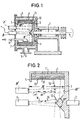
- FIG. 1 and 2 show a filter centrifuge with a centrifuge drum 1, which is composed of drum shaft 2, drum base 3, sieve jacket 4 and drum rim 5.
- the drum shaft 2 is in a filter drum 1 enclosing Centrifuge housing 6 stored.
- An ultrasonic sensor is in the housing cover 7 8, a reference ultrasonic sensor 8 'and one inside the filter drum 1, the Process room, projecting suspension filling pipe 9 arranged.
- On the inside of the The drum base 3 is in the middle a deflection cone 10 having a reflection surface arranged.
- the remaining annular surface of the drum base is a flat reference reflection surface 10 '.
- the centrifuge drum 1 is filled with a suspension, the solid components have settled in a solid layer or in a solid cake 11, Over which the liquid layer 12 consisting of filtrate with the filling surface 13 is located.
- the filtrate penetrates in the operation of the filter centrifuge the solid cake 11 and is thrown over the sieve jacket 4 and over the drain opening 14 of the centrifuge housing 6 is derived.
- the solids of the remaining Solid cake 11 are intermittently through a peeling device (not shown) carried out.
- the sound signal 15 emitted by the ultrasonic sensor 8 (arrow with continuous line), which is deflected by 90 ° at the deflection cone 10.
- the sound signal 15 is reflected and arrives as an echo signal 16 (Arrow with broken line) back to the ultrasonic sensor, where it is from Receiver unit is registered. From the echo time of sound signal 15 and Echo signal 16 becomes the distance between the ultrasonic sensor and the filling surface 13 determined and then determined the thickness of the filling layer.
- FIG. 2 also shows the reference sound signal 15 '(arrow with a solid line) emitted by the reference ultrasound sensor 8', which is reflected on the flat reference reflection surface 10 'arranged at the fixed reference distance "R" and as a reference echo signal 16 '(Arrow with broken line) to the reference ultrasonic sensor 8'. From the echo run time of the sound beams 15 'and 16' can due to the fixed reference distance R "changes in the gas composition and the associated changes in the scanning speed are determined and taken into account in the measurement result obtained by the ultrasonic sensor.
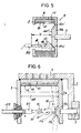
- the deflection surface 4 can also be designed as a flat truncated cone 10b, in which the Shell surface 10b 'as a measuring beam deflection surface and the flat truncated cone surface 10b '' serves as a reference reflection surface. 4 in the embodiment the measuring beam deflection surface and the reference reflection surface separately from Ultrasonic sensor 8 and acted upon by the reference ultrasonic sensor 8 '.
- a combined ultrasonic sensor 80 which performs both the function of measuring the fill level and the function of the reference measurement over the constant reference distance R "is fulfilled.
- the sound beam of the combined ultrasound sensor 80 is directed both at the reference reflection surface and at the measuring beam deflection surface.
- both the echo propagation times of the sound beam directed onto the filling surface and the echo propagation times of the one directed at the surface are measured Reference distance arranged reference reflection surface directed sound beam registered and evaluated in a downstream comparator circuit (not shown).
- a combined ultrasonic sensor 81 can also end the filling tube 109 of an inverting filter centrifuge protruding into the process space his.
- the reference reflection surface 10c ′′ and the measuring beam deflection surface 10c ' are on a truncated cone arranged centrally on the drum base 3a 10c directed, in which the central flat truncated cone surface from the central Area of the sound beam and the outer surface of the truncated cone 10c of the outer areas of the sound beam is applied.
- the filter centrifuge shown in Fig. 7 corresponds otherwise the embodiment according to FIG. 1.
- the above-described ultrasonic measuring devices for measuring the fill level are in the centrifuge drum of a filter centrifuge with measuring beam deflection surfaces equipped that ensure that the necessary for a perfect ultrasonic measurement Minimum distances between the ultrasonic sensor and the filling surface can be met.
- the arrangement of measuring beam deflection surfaces can therefore necessary for filter centrifuges with relatively small process rooms or centrifuges, in the process rooms of which there are internals (e.g. the spacer bolts 107 in the drum of an inverting filter centrifuge), which is a direct Impair sound beam routing from the ultrasonic sensor to the filling surface.
- the present invention is not limited to centrifuges in which the The level must be measured via measuring beam deflection surfaces.
- the invention was also based on linear reference measuring distances with a fixed distance R ". However, it may also be necessary for these reference measurement sections to guide them over deflection surfaces to reference reflection surfaces if longer beam guidance sections are required for measurement reasons.
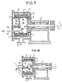
- FIGS. 8 and 9 show a filter centrifuge in which the sound beams of the combined ultrasonic sensor 83, without measuring beam deflection surfaces, alternately directly on the filling surface 13 and on the surface at a fixed reference distance
- the combined ultrasonic sensor 83 is pivotably arranged on a holding arm 7a fastened to the housing cover 7, the pivoting being effected via a hydraulic actuating cylinder 7b.
- the ultrasonic sensor is in the position according to FIG to the at the reference distance R "located reference reflection surface 10 ′′ and in the position according to FIG. 9 directly onto the filling surface 13.
- the filter centrifuge shown in FIGS. 8 and 9 otherwise corresponds to the embodiment according to FIG. 1.
- a combined ultrasonic sensor 84 for ultrasonic sensors for reference sound signals is arranged, the sound signals via a measuring beam deflection surface 10d to Filling surface 13 emits and the corresponding echo signals registered as also sends out reference signals and detects their echo signals.
- the reference reflective surface 100 is fixed via a holding space 100a with the combined ultrasonic sensor (84) connected.
- FIG. 12 shows a filter centrifuge, which also largely corresponds to the filter centrifuge according to FIG. 1, but in which the function of a separate ultrasonic sensor for reference signals is taken over by a combined ultrasonic sensor 85, some of whose ultrasonic signals are directed directly onto the filling surface 13 and on the other hand, are reflected on the reference reflection surface 101 by the holding arm 101a fixedly connected to the ultrasonic sensor 85 at a constant reference distance R "is held.
Landscapes
- Physics & Mathematics (AREA)
- Acoustics & Sound (AREA)
- Electromagnetism (AREA)
- Thermal Sciences (AREA)
- Fluid Mechanics (AREA)
- General Physics & Mathematics (AREA)
- Centrifugal Separators (AREA)
- Measurement Of Levels Of Liquids Or Fluent Solid Materials (AREA)
Applications Claiming Priority (2)
| Application Number | Priority Date | Filing Date | Title |
|---|---|---|---|
| DE19919118 | 1999-04-27 | ||
| DE1999119118 DE19919118C2 (de) | 1999-04-27 | 1999-04-27 | Verfahren zur Messung der Füllstandshöhe in einer Zentrifugentrommel einer Filterzentrifuge und Vorrichtung zur Durchführung des Verfahrens |
Publications (3)
| Publication Number | Publication Date |
|---|---|
| EP1063016A2 true EP1063016A2 (fr) | 2000-12-27 |
| EP1063016A3 EP1063016A3 (fr) | 2002-01-30 |
| EP1063016B1 EP1063016B1 (fr) | 2007-02-28 |
Family
ID=7906032
Family Applications (1)
| Application Number | Title | Priority Date | Filing Date |
|---|---|---|---|
| EP20000108837 Expired - Lifetime EP1063016B1 (fr) | 1999-04-27 | 2000-04-26 | Procédé et dispositif de mesure du niveau de remplissage d'une centrifugeuse filtrante |
Country Status (3)
| Country | Link |
|---|---|
| EP (1) | EP1063016B1 (fr) |
| DE (2) | DE19919118C2 (fr) |
| ES (1) | ES2282067T3 (fr) |
Cited By (1)
| Publication number | Priority date | Publication date | Assignee | Title |
|---|---|---|---|---|
| CN103100489A (zh) * | 2013-01-29 | 2013-05-15 | 山东城矿再生资源有限公司 | 离心过滤式固液分理器 |
Families Citing this family (3)
| Publication number | Priority date | Publication date | Assignee | Title |
|---|---|---|---|---|
| WO2002055968A1 (fr) * | 2000-12-04 | 2002-07-18 | Metso Woodhandling Oy | Procede de mesure du degre de remplissage d'un tambour |
| DE102004049241A1 (de) * | 2004-10-09 | 2006-04-20 | Sanofi-Aventis Deutschland Gmbh | Trockner und Verfahren zum Steuern eines Trockners |
| US11020753B2 (en) | 2015-10-02 | 2021-06-01 | Bjarne Christian Nielsen Holding Aps | Apparatus and method for monitoring and controlling a centrifugal |
Family Cites Families (4)
| Publication number | Priority date | Publication date | Assignee | Title |
|---|---|---|---|---|
| US4210969A (en) * | 1978-03-13 | 1980-07-01 | The Stoneleigh Trust | Sonic ranging systems to eliminate errors due to variations in the sound velocity in the medium |
| US5897786A (en) * | 1997-03-24 | 1999-04-27 | The Western States Machine Company | Method and apparatus for determining thickness of a charge wall being formed in a centrifugal machine |
| DE19716129C1 (de) * | 1997-04-17 | 1998-10-15 | Krauss Maffei Ag | Filterzentrifuge |
| US6063292A (en) * | 1997-07-18 | 2000-05-16 | Baker Hughes Incorporated | Method and apparatus for controlling vertical and horizontal basket centrifuges |
-
1999
- 1999-04-27 DE DE1999119118 patent/DE19919118C2/de not_active Expired - Fee Related
-
2000
- 2000-04-26 ES ES00108837T patent/ES2282067T3/es not_active Expired - Lifetime
- 2000-04-26 DE DE50014103T patent/DE50014103D1/de not_active Expired - Lifetime
- 2000-04-26 EP EP20000108837 patent/EP1063016B1/fr not_active Expired - Lifetime
Cited By (1)
| Publication number | Priority date | Publication date | Assignee | Title |
|---|---|---|---|---|
| CN103100489A (zh) * | 2013-01-29 | 2013-05-15 | 山东城矿再生资源有限公司 | 离心过滤式固液分理器 |
Also Published As
| Publication number | Publication date |
|---|---|
| DE19919118C2 (de) | 2003-02-27 |
| EP1063016A3 (fr) | 2002-01-30 |
| DE19919118A1 (de) | 2000-11-09 |
| EP1063016B1 (fr) | 2007-02-28 |
| ES2282067T3 (es) | 2007-10-16 |
| DE50014103D1 (de) | 2007-04-12 |
Similar Documents
| Publication | Publication Date | Title |
|---|---|---|
| DE2713921C2 (de) | Vorrichtung zum Messen der radialen Abmessungen eines Rohres mittels Ultraschall | |
| EP1491886B1 (fr) | Appareil et procédé pour l'étalonnage et inspection ultrasonique des echantillons cylindriques | |
| DE2204237B2 (de) | Vorrichtung mit einer Ultraschallsonde zur Prüfung von Werkstücken | |
| EP2174093A1 (fr) | Dispositif destiné à déterminer la position d'un piston dans un cylindre | |
| DE2611514B2 (de) | Oberflächen-Abtastprüfvorrichtung | |
| DE102019106427B4 (de) | Wandler und Wandleranordnung für Ultraschall-Prüfkopfsysteme, Ultraschall-Prüfkopfsystem und Prüfverfahren | |
| DE2732631A1 (de) | Vorrichtung zur ultraschallpruefung von rohren | |
| EP1344052B1 (fr) | Procede et palpeur a rouleau pour l'examen par ultrasons de cordons de soudure a recouvrement entre des toles selon la technique des impulsions | |
| DE2636246A1 (de) | Verfahren und vorrichtung zum ultraschallpruefen der stutzenfelder eines reaktordruckbehaelters | |
| EP1063016A2 (fr) | Procédé et dispositif de mesure du niveau de remplissage d'une centrifugeuse filtrante | |
| DE2717301B1 (de) | Messumformer zur kapazitiven Fuellstandsmessung von Fluessigkeitsfuellungen | |
| EP0590165B1 (fr) | Buse électrostatique, en particulier pour injecter des matériaux fluides à haute viscosité | |
| DE19723681A1 (de) | Vorrichtung zur Bestimmung von insbesondere elektrochemischen und/oder optischen Eigenschaften von Flüssigkeiten | |
| DE102005009262A1 (de) | Verfahren zur Messung der Schichtdicke | |
| DE4402463C2 (de) | Vorrichtung zur diskontinuierlichen Erfassung der Dicke einer Schicht auf einer Metallschmelze | |
| EP0138017A1 (fr) | Procédé de mesure de débit par ultrason d'après le principe Doppler avec résolution spatiale améliorée | |
| DE3619916C2 (fr) | ||
| EP0766822A1 (fr) | Dispositif permettant de mesurer les irregularites de parois interieures de cuves, a l'aide d'ultrasons | |
| EP0647480B1 (fr) | Procédé d'extraction de bouteilles réutilisables de leur cycle d'utilisation | |
| EP0598926A1 (fr) | Procédé et appareil pour la fabrication de plaques d'impression flexographiques | |
| DE2510537A1 (de) | Verfahren zum schnellen messen des abstandes eines objektes von einer bezugsebene und der geschwindigkeitskomponente des objektes senkrecht zu der bezugsebene | |
| DE3305737A1 (de) | Vorrichtung zum bestimmen der senkungsgeschwindigkeit der roten blutkoerperchen | |
| WO2019158345A1 (fr) | Dispositif destiné à déterminer une hauteur et/ou une qualité d'un fluide dans un récipient de fluide | |
| DE69106997T2 (de) | Impulsechogerät und Verfahren zum Feststellen von Fehlstellen. | |
| DE2939480A1 (de) | Verfahren zur ermittlung von rissen u.dgl. in einem rohr mit hilfe von ultraschall |
Legal Events
| Date | Code | Title | Description |
|---|---|---|---|
| PUAI | Public reference made under article 153(3) epc to a published international application that has entered the european phase |
Free format text: ORIGINAL CODE: 0009012 |
|
| AK | Designated contracting states |
Kind code of ref document: A2 Designated state(s): AT BE CH CY DE DK ES FI FR GB GR IE IT LI LU MC NL PT SE Kind code of ref document: A2 Designated state(s): CH DE ES FR GB IT LI |
|
| AX | Request for extension of the european patent |
Free format text: AL;LT;LV;MK;RO;SI |
|
| PUAL | Search report despatched |
Free format text: ORIGINAL CODE: 0009013 |
|
| AK | Designated contracting states |
Kind code of ref document: A3 Designated state(s): AT BE CH CY DE DK ES FI FR GB GR IE IT LI LU MC NL PT SE |
|
| AX | Request for extension of the european patent |
Free format text: AL;LT;LV;MK;RO;SI |
|
| RIC1 | Information provided on ipc code assigned before grant |
Free format text: 7B 04B 11/04 A, 7G 01F 23/296 B |
|
| RAP1 | Party data changed (applicant data changed or rights of an application transferred) |
Owner name: KRAUSS-MAFFEI PROCESS TECHNOLOGY AG |
|
| 17P | Request for examination filed |
Effective date: 20020610 |
|
| AKX | Designation fees paid |
Free format text: CH DE ES FR GB IT LI |
|
| 17Q | First examination report despatched |
Effective date: 20050330 |
|
| GRAP | Despatch of communication of intention to grant a patent |
Free format text: ORIGINAL CODE: EPIDOSNIGR1 |
|
| GRAS | Grant fee paid |
Free format text: ORIGINAL CODE: EPIDOSNIGR3 |
|
| GRAA | (expected) grant |
Free format text: ORIGINAL CODE: 0009210 |
|
| AK | Designated contracting states |
Kind code of ref document: B1 Designated state(s): CH DE ES FR GB IT LI |
|
| REG | Reference to a national code |
Ref country code: GB Ref legal event code: FG4D Free format text: NOT ENGLISH |
|
| REG | Reference to a national code |
Ref country code: CH Ref legal event code: EP |
|
| REF | Corresponds to: |
Ref document number: 50014103 Country of ref document: DE Date of ref document: 20070412 Kind code of ref document: P |
|
| GBT | Gb: translation of ep patent filed (gb section 77(6)(a)/1977) |
Effective date: 20070523 |
|
| REG | Reference to a national code |
Ref country code: CH Ref legal event code: NV Representative=s name: TROESCH SCHEIDEGGER WERNER AG |
|
| ET | Fr: translation filed | ||
| REG | Reference to a national code |
Ref country code: ES Ref legal event code: FG2A Ref document number: 2282067 Country of ref document: ES Kind code of ref document: T3 |
|
| PLBE | No opposition filed within time limit |
Free format text: ORIGINAL CODE: 0009261 |
|
| STAA | Information on the status of an ep patent application or granted ep patent |
Free format text: STATUS: NO OPPOSITION FILED WITHIN TIME LIMIT |
|
| 26N | No opposition filed |
Effective date: 20071129 |
|
| PGFP | Annual fee paid to national office [announced via postgrant information from national office to epo] |
Ref country code: ES Payment date: 20150427 Year of fee payment: 16 |
|
| REG | Reference to a national code |
Ref country code: FR Ref legal event code: PLFP Year of fee payment: 17 |
|
| PGFP | Annual fee paid to national office [announced via postgrant information from national office to epo] |
Ref country code: DE Payment date: 20160623 Year of fee payment: 17 Ref country code: GB Payment date: 20160422 Year of fee payment: 17 |
|
| PGFP | Annual fee paid to national office [announced via postgrant information from national office to epo] |
Ref country code: FR Payment date: 20160422 Year of fee payment: 17 |
|
| REG | Reference to a national code |
Ref country code: DE Ref legal event code: R119 Ref document number: 50014103 Country of ref document: DE |
|
| GBPC | Gb: european patent ceased through non-payment of renewal fee |
Effective date: 20170426 |
|
| REG | Reference to a national code |
Ref country code: FR Ref legal event code: ST Effective date: 20171229 |
|
| PG25 | Lapsed in a contracting state [announced via postgrant information from national office to epo] |
Ref country code: DE Free format text: LAPSE BECAUSE OF NON-PAYMENT OF DUE FEES Effective date: 20171103 Ref country code: FR Free format text: LAPSE BECAUSE OF NON-PAYMENT OF DUE FEES Effective date: 20170502 |
|
| PG25 | Lapsed in a contracting state [announced via postgrant information from national office to epo] |
Ref country code: GB Free format text: LAPSE BECAUSE OF NON-PAYMENT OF DUE FEES Effective date: 20170426 |
|
| PG25 | Lapsed in a contracting state [announced via postgrant information from national office to epo] |
Ref country code: ES Free format text: LAPSE BECAUSE OF NON-PAYMENT OF DUE FEES Effective date: 20160427 |
|
| REG | Reference to a national code |
Ref country code: ES Ref legal event code: FD2A Effective date: 20180626 |
|
| PGFP | Annual fee paid to national office [announced via postgrant information from national office to epo] |
Ref country code: CH Payment date: 20180424 Year of fee payment: 19 |
|
| PGFP | Annual fee paid to national office [announced via postgrant information from national office to epo] |
Ref country code: IT Payment date: 20180420 Year of fee payment: 19 |
|
| REG | Reference to a national code |
Ref country code: CH Ref legal event code: PL |
|
| PG25 | Lapsed in a contracting state [announced via postgrant information from national office to epo] |
Ref country code: LI Free format text: LAPSE BECAUSE OF NON-PAYMENT OF DUE FEES Effective date: 20190430 Ref country code: CH Free format text: LAPSE BECAUSE OF NON-PAYMENT OF DUE FEES Effective date: 20190430 |
|
| PG25 | Lapsed in a contracting state [announced via postgrant information from national office to epo] |
Ref country code: IT Free format text: LAPSE BECAUSE OF NON-PAYMENT OF DUE FEES Effective date: 20190426 |