EP1063130B1 - Verfahren und Vorrichtung zur Steuerung eines Generators - Google Patents
Verfahren und Vorrichtung zur Steuerung eines Generators Download PDFInfo
- Publication number
- EP1063130B1 EP1063130B1 EP20000110471 EP00110471A EP1063130B1 EP 1063130 B1 EP1063130 B1 EP 1063130B1 EP 20000110471 EP20000110471 EP 20000110471 EP 00110471 A EP00110471 A EP 00110471A EP 1063130 B1 EP1063130 B1 EP 1063130B1
- Authority
- EP
- European Patent Office
- Prior art keywords
- generator
- internal combustion
- combustion engine
- belt
- excitation
- Prior art date
- Legal status (The legal status is an assumption and is not a legal conclusion. Google has not performed a legal analysis and makes no representation as to the accuracy of the status listed.)
- Expired - Lifetime
Links
Images
Classifications
-
- H—ELECTRICITY
- H02—GENERATION; CONVERSION OR DISTRIBUTION OF ELECTRIC POWER
- H02P—CONTROL OR REGULATION OF ELECTRIC MOTORS, ELECTRIC GENERATORS OR DYNAMO-ELECTRIC CONVERTERS; CONTROLLING TRANSFORMERS, REACTORS OR CHOKE COILS
- H02P9/00—Arrangements for controlling electric generators for the purpose of obtaining a desired output
- H02P9/04—Control effected upon non-electric prime mover and dependent upon electric output value of the generator
-
- H—ELECTRICITY
- H02—GENERATION; CONVERSION OR DISTRIBUTION OF ELECTRIC POWER
- H02J—ELECTRIC POWER NETWORKS; CIRCUIT ARRANGEMENTS OR SYSTEMS FOR SUPPLYING OR DISTRIBUTING ELECTRIC POWER; SYSTEMS FOR STORING ELECTRIC ENERGY
- H02J7/00—Circuit arrangements for charging or discharging batteries or for supplying loads from batteries
- H02J7/14—Circuit arrangements for charging or discharging batteries or for supplying loads from batteries for charging batteries from dynamo-electric generators driven at varying speed, e.g. on vehicle
- H02J7/1446—Circuit arrangements for charging or discharging batteries or for supplying loads from batteries for charging batteries from dynamo-electric generators driven at varying speed, e.g. on vehicle in response to parameters of a vehicle
-
- Y—GENERAL TAGGING OF NEW TECHNOLOGICAL DEVELOPMENTS; GENERAL TAGGING OF CROSS-SECTIONAL TECHNOLOGIES SPANNING OVER SEVERAL SECTIONS OF THE IPC; TECHNICAL SUBJECTS COVERED BY FORMER USPC CROSS-REFERENCE ART COLLECTIONS [XRACs] AND DIGESTS
- Y02—TECHNOLOGIES OR APPLICATIONS FOR MITIGATION OR ADAPTATION AGAINST CLIMATE CHANGE
- Y02T—CLIMATE CHANGE MITIGATION TECHNOLOGIES RELATED TO TRANSPORTATION
- Y02T10/00—Road transport of goods or passengers
- Y02T10/80—Technologies aiming to reduce greenhouse gasses emissions common to all road transportation technologies
- Y02T10/92—Energy efficient charging or discharging systems for batteries, ultracapacitors, supercapacitors or double-layer capacitors specially adapted for vehicles
Definitions
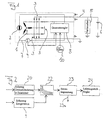
- Fig. 1 is designed as an alternator 1 alternator represented for a motor vehicle.
- the alternator 1 comprises a field circuit 7 having a field coil system 2 and has output terminals via a rectifier bridge circuit 3 power in a vehicle electrical system 4 of the motor vehicle feed.
- This electrical system 4 supplies consumers 5, such as For example, light sources and electric motors, and a motor vehicle battery 6 with electrical energy.
- a generator controller 8 provided, which also with a rectified Three-phase voltage is fed from the alternator 1 and with a not shown in Fig. 1 power level is provided, the current for the exciting field coil system. 2 provides.
Landscapes
- Engineering & Computer Science (AREA)
- Power Engineering (AREA)
- Control Of Eletrric Generators (AREA)
Description
- Fig. 1
- einen Schaltplan eines Generators mit Generatorregler und eines angeschlossenen Bordnetzes eines Kraftfahrzeuges und
- Fig. 2
- ein Blockdiagramm einer Vorrichtung zur Steuerung des Generators von Fig. 1 mit riemenrutschverhindernder Generatorerregerstrombegrenzung.
Claims (4)
- Verfahren zur Steuerung eines Generators, der mechanisch über einen Riementrieb an eine mit wechselnder Last betriebene Brennkraftmaschine angekoppelt ist, bei demdadurch gekennzeichnet, daßdie zeitliche Änderung der Drehzahl der Brennkraftmaschine ermittelt und in Abhängigkeit davon die Generatorerregung eingestellt wird,das über den Riementrieb von der Brennkraftmaschine auf den Generator (1) übertragene Drehmoment durch entsprechende Begrenzung der Generatorerregung auf einen von der ermittelten Drehzahländerungsrate abhängigen Riemenrutschverhinderungs-Grenzwert begrenzt wird und dieser Riemenrutschverhinderungs- Grenzwert einem Kennfeld entnommen wird.
- Verfahren nach Anspruch 1,
dadurch gekennzeichnet, daß
die Begrenzung der Generatorerregung durch Begrenzung des Erregerstroms auf einen maximalen Erregerstromwert erfolgt, der in Abhängigkeit von der ermittelten zeitlichen Änderung der Drehzahl der Brennkraftmaschine bestimmt wird. - Vorrichtung zur Steuerung eines Generators, der mechanisch über einen Riementrieb an eine mit wechselnder Last betriebene Brennkraftmaschine angekoppelt ist, mitdadurch gekennzeichnet, daßMitteln zur Ermittlung der zeitlichen Drehzahländerung der Brennkraftmaschine undMitteln zur Einstellung der Generatorerregung in Abhängigkeit von der ermittelten zeitlichen Drehzahländerung,die Generatorerregungs-Einstellmittel (8, 20, 22, 23, 24) eine Kennfeldstufe (22) aufweisen, die das über den Riementrieb von der Brennkraftmaschine auf den Generator (1) übertragene Drehmoment durch entsprechende Begrenzung der Generatorerregung auf einen Riemenrutschverhinderungs-Grenzwert begrenzt.
- Vorrichtung nach Anspruch nach Anspruch 3,
dadurch gekennzeichnet, daß
die Generatorerregungs-Begrenzungsmittel Erregerstrom-Begrenzungsmittel (20, 22, 23) umfassen, die den Erregerstrom auf einen maximalen Erregerstrom begrenzen, der in Abhängigkeit von der ermittelten zeitlichen Drehzahländerung der Brennkraftmaschine bestimmt wird.
Applications Claiming Priority (2)
| Application Number | Priority Date | Filing Date | Title |
|---|---|---|---|
| DE19929060 | 1999-06-25 | ||
| DE1999129060 DE19929060C1 (de) | 1999-06-25 | 1999-06-25 | Verfahren und Vorrichtung zur Steuerung eines Generators |
Publications (3)
| Publication Number | Publication Date |
|---|---|
| EP1063130A2 EP1063130A2 (de) | 2000-12-27 |
| EP1063130A3 EP1063130A3 (de) | 2002-09-18 |
| EP1063130B1 true EP1063130B1 (de) | 2005-02-23 |
Family
ID=7912455
Family Applications (1)
| Application Number | Title | Priority Date | Filing Date |
|---|---|---|---|
| EP20000110471 Expired - Lifetime EP1063130B1 (de) | 1999-06-25 | 2000-05-17 | Verfahren und Vorrichtung zur Steuerung eines Generators |
Country Status (3)
| Country | Link |
|---|---|
| EP (1) | EP1063130B1 (de) |
| DE (1) | DE19929060C1 (de) |
| ES (1) | ES2235711T3 (de) |
Families Citing this family (3)
| Publication number | Priority date | Publication date | Assignee | Title |
|---|---|---|---|---|
| JP4333022B2 (ja) * | 2000-11-10 | 2009-09-16 | 株式会社デンソー | 車両用発電機の発電制御システム |
| DE102008042352A1 (de) | 2008-09-25 | 2010-04-08 | Robert Bosch Gmbh | Ansteuerung eines Synchrongleichrichters |
| DE102012204751B4 (de) * | 2012-03-26 | 2018-12-20 | Robert Bosch Gmbh | Verfahren zur Überprüfung einer Erregerstrommessung einer Synchronmaschine im Generatorbetrieb |
Family Cites Families (7)
| Publication number | Priority date | Publication date | Assignee | Title |
|---|---|---|---|---|
| US1338041A (en) * | 1916-08-19 | 1920-04-27 | Stone J & Co Ltd | Device for preventing excessive wear on car-lighting dynamos |
| DE2848556A1 (de) * | 1978-11-09 | 1980-05-22 | Bosch Gmbh Robert | Verfahren und vorrichtung zur ausnutzung der vollen motorleistung bei beschleunigungsvorgaengen bei kraftfahrzeugen |
| US4659977A (en) * | 1984-10-01 | 1987-04-21 | Chrysler Motors Corporation | Microcomputer controlled electronic alternator for vehicles |
| JPS6284399U (de) * | 1985-11-18 | 1987-05-29 | ||
| DE4042347A1 (de) * | 1990-04-27 | 1991-11-07 | Basilius Glawleschkoff | Einrichtung zur verzoegerung der generatorerregung in kraftfahrzeugen |
| DE4307907A1 (de) * | 1993-03-12 | 1994-05-05 | Daimler Benz Ag | Verfahren zur Regelung eines Generators in einem Kraftfahrzeug |
| JPH08126223A (ja) * | 1994-10-26 | 1996-05-17 | Mitsubishi Electric Corp | 交流発電機の制御装置 |
-
1999
- 1999-06-25 DE DE1999129060 patent/DE19929060C1/de not_active Expired - Fee Related
-
2000
- 2000-05-17 ES ES00110471T patent/ES2235711T3/es not_active Expired - Lifetime
- 2000-05-17 EP EP20000110471 patent/EP1063130B1/de not_active Expired - Lifetime
Also Published As
| Publication number | Publication date |
|---|---|
| EP1063130A2 (de) | 2000-12-27 |
| DE19929060C1 (de) | 2000-10-05 |
| EP1063130A3 (de) | 2002-09-18 |
| ES2235711T3 (es) | 2005-07-16 |
Similar Documents
| Publication | Publication Date | Title |
|---|---|---|
| DE69526148T2 (de) | Ladeeinrichtung für ein Fahrzeug | |
| DE102007017806B4 (de) | Fahrzeug-Stromerzeugungssteuervorrichtung | |
| DE69518553T2 (de) | Vorrichtung zur Leistungserzeugung für Fahrzeuge | |
| DE102007013752B4 (de) | Elektrisches Energieerzeugungs-Steuersystem | |
| DE102007008858A1 (de) | Antriebsriemenschlupfdetektion | |
| DE102006003425A1 (de) | Verfahren und Vorrichtung zum Berechnen/Steuern eines Energieerzeugungsdrehmoments | |
| DE2821455A1 (de) | Regelungssystem fuer einen selbsterregten wechselstromgenerator mit einer tertiaer- oder hilfswicklung | |
| DE3619703A1 (de) | Motorgetriebenes leistungslenkgeraet | |
| EP1490960A1 (de) | Verfahren und vorrichtung zur ermittlung der rotortemperatur bei einer pm-synchronmaschine | |
| WO2013087528A1 (de) | Hochfahren des erregerstroms eines an ein bordnetz eines kraftfahrzeugs angeschlossenen mehrphasenwechselstrom-generators beim aktivieren des generators | |
| EP3205014A1 (de) | Steuervorrichtung für eine elektromaschine, fahrzeug und verfahren | |
| EP0690556B1 (de) | Stillstandserkennung beim Wiederanlassen eines stromrichtergespeisten Drehstrommotors ohne Drehzahlgeber | |
| DE112013005317T5 (de) | Verfahren und Vorrichtung zur Verringerung einer Drehmomentabweichung in Motorantriebssystemen | |
| DE102010060413A1 (de) | Leistungserzeugungssteuervorrichtung und Leistungserzeugungssteuersystem zur Verwendung in Fahrzeugen | |
| EP1063130B1 (de) | Verfahren und Vorrichtung zur Steuerung eines Generators | |
| DE102010037503A1 (de) | Steuervorrichtung, die in einer drehenden elektrischen Maschine eines Fahrzeugs angeordnet ist | |
| DE10148246A1 (de) | Regelung und elektrisches System für Impulsaufladung einer Anlasser-Drehstromlichtmaschine | |
| DE102006048396A1 (de) | Steuergerät zum Erzeugen von Energie für ein Fahrzeug | |
| WO2002014817A1 (de) | Verfahren und vorrichtung zur bestimmung eines drehmoments einer elektrischen maschine | |
| DE102007004171B4 (de) | Verfahren und Vorrichtung zum Einstellen einer Leerlaufdrehzahl | |
| DE112017003538T5 (de) | Steuerungsgerät und steuerungsverfahren für eine rotierende elektrische maschine | |
| DE102011003946A1 (de) | Verfahren zum Regeln eines von einer elektrischen Maschine in einem Kraftfahrzeug abgegebenen Ist-Drehmoments auf ein Soll-Drehmoment | |
| EP1469586B1 (de) | Vorrichtung zur Verbesserung des Start-Stopp-Betriebes eines Fahrzeuges | |
| DE102015211248A1 (de) | Verfahren zum Betreiben einer fremderregten elektrischen Maschine | |
| DE102011087523A1 (de) | Verfahren zum Betreiben einer fremderregten elektrischen Maschine in einem Kraftfahrzeug |
Legal Events
| Date | Code | Title | Description |
|---|---|---|---|
| PUAI | Public reference made under article 153(3) epc to a published international application that has entered the european phase |
Free format text: ORIGINAL CODE: 0009012 |
|
| AK | Designated contracting states |
Kind code of ref document: A2 Designated state(s): AT BE CH CY DE DK ES FI FR GB GR IE IT LI LU MC NL PT SE |
|
| AX | Request for extension of the european patent |
Free format text: AL;LT;LV;MK;RO;SI |
|
| PUAL | Search report despatched |
Free format text: ORIGINAL CODE: 0009013 |
|
| AK | Designated contracting states |
Kind code of ref document: A3 Designated state(s): AT BE CH CY DE DK ES FI FR GB GR IE IT LI LU MC NL PT SE |
|
| AX | Request for extension of the european patent |
Free format text: AL;LT;LV;MK;RO;SI |
|
| 17P | Request for examination filed |
Effective date: 20020816 |
|
| AKX | Designation fees paid |
Designated state(s): ES FR GB IT SE |
|
| REG | Reference to a national code |
Ref country code: DE Ref legal event code: 8566 |
|
| 17Q | First examination report despatched |
Effective date: 20031128 |
|
| GRAP | Despatch of communication of intention to grant a patent |
Free format text: ORIGINAL CODE: EPIDOSNIGR1 |
|
| GRAS | Grant fee paid |
Free format text: ORIGINAL CODE: EPIDOSNIGR3 |
|
| GRAA | (expected) grant |
Free format text: ORIGINAL CODE: 0009210 |
|
| AK | Designated contracting states |
Kind code of ref document: B1 Designated state(s): ES FR GB IT SE |
|
| REG | Reference to a national code |
Ref country code: GB Ref legal event code: FG4D Free format text: NOT ENGLISH |
|
| REG | Reference to a national code |
Ref country code: IE Ref legal event code: FG4D Free format text: GERMAN |
|
| GBT | Gb: translation of ep patent filed (gb section 77(6)(a)/1977) |
Effective date: 20050323 |
|
| REG | Reference to a national code |
Ref country code: SE Ref legal event code: TRGR |
|
| REG | Reference to a national code |
Ref country code: ES Ref legal event code: FG2A Ref document number: 2235711 Country of ref document: ES Kind code of ref document: T3 |
|
| PLBE | No opposition filed within time limit |
Free format text: ORIGINAL CODE: 0009261 |
|
| STAA | Information on the status of an ep patent application or granted ep patent |
Free format text: STATUS: NO OPPOSITION FILED WITHIN TIME LIMIT |
|
| ET | Fr: translation filed | ||
| 26N | No opposition filed |
Effective date: 20051124 |
|
| PGFP | Annual fee paid to national office [announced via postgrant information from national office to epo] |
Ref country code: ES Payment date: 20090521 Year of fee payment: 10 |
|
| PGFP | Annual fee paid to national office [announced via postgrant information from national office to epo] |
Ref country code: SE Payment date: 20090514 Year of fee payment: 10 Ref country code: IT Payment date: 20090525 Year of fee payment: 10 Ref country code: FR Payment date: 20090513 Year of fee payment: 10 |
|
| PGFP | Annual fee paid to national office [announced via postgrant information from national office to epo] |
Ref country code: GB Payment date: 20090522 Year of fee payment: 10 |
|
| REG | Reference to a national code |
Ref country code: FR Ref legal event code: CD Ref country code: FR Ref legal event code: CA |
|
| GBPC | Gb: european patent ceased through non-payment of renewal fee |
Effective date: 20100517 |
|
| EUG | Se: european patent has lapsed | ||
| REG | Reference to a national code |
Ref country code: FR Ref legal event code: ST Effective date: 20110131 |
|
| PG25 | Lapsed in a contracting state [announced via postgrant information from national office to epo] |
Ref country code: IT Free format text: LAPSE BECAUSE OF NON-PAYMENT OF DUE FEES Effective date: 20100517 Ref country code: SE Free format text: LAPSE BECAUSE OF NON-PAYMENT OF DUE FEES Effective date: 20100518 |
|
| PG25 | Lapsed in a contracting state [announced via postgrant information from national office to epo] |
Ref country code: FR Free format text: LAPSE BECAUSE OF NON-PAYMENT OF DUE FEES Effective date: 20100531 |
|
| PG25 | Lapsed in a contracting state [announced via postgrant information from national office to epo] |
Ref country code: GB Free format text: LAPSE BECAUSE OF NON-PAYMENT OF DUE FEES Effective date: 20100517 |
|
| REG | Reference to a national code |
Ref country code: ES Ref legal event code: FD2A Effective date: 20111118 |
|
| PG25 | Lapsed in a contracting state [announced via postgrant information from national office to epo] |
Ref country code: ES Free format text: LAPSE BECAUSE OF NON-PAYMENT OF DUE FEES Effective date: 20100518 |