EP1063167A2 - Toilettensystem, insbesondere für Verkehrsmittel - Google Patents
Toilettensystem, insbesondere für Verkehrsmittel Download PDFInfo
- Publication number
- EP1063167A2 EP1063167A2 EP00112925A EP00112925A EP1063167A2 EP 1063167 A2 EP1063167 A2 EP 1063167A2 EP 00112925 A EP00112925 A EP 00112925A EP 00112925 A EP00112925 A EP 00112925A EP 1063167 A2 EP1063167 A2 EP 1063167A2
- Authority
- EP
- European Patent Office
- Prior art keywords
- layer
- nano
- toilet
- toilet bowl
- toilet system
- Prior art date
- Legal status (The legal status is an assumption and is not a legal conclusion. Google has not performed a legal analysis and makes no representation as to the accuracy of the status listed.)
- Granted
Links
- 238000000034 method Methods 0.000 claims abstract description 27
- 239000002052 molecular layer Substances 0.000 claims abstract description 27
- 238000004519 manufacturing process Methods 0.000 claims abstract description 10
- XLYOFNOQVPJJNP-UHFFFAOYSA-N water Substances O XLYOFNOQVPJJNP-UHFFFAOYSA-N 0.000 claims description 28
- 238000011010 flushing procedure Methods 0.000 claims description 27
- 238000000576 coating method Methods 0.000 claims description 20
- 239000011248 coating agent Substances 0.000 claims description 18
- 238000005516 engineering process Methods 0.000 claims description 10
- 150000001875 compounds Chemical class 0.000 claims description 8
- 239000000356 contaminant Substances 0.000 claims description 8
- 238000004140 cleaning Methods 0.000 claims description 7
- 229910052751 metal Inorganic materials 0.000 claims description 5
- 239000002184 metal Substances 0.000 claims description 5
- 238000005240 physical vapour deposition Methods 0.000 claims description 5
- 239000000126 substance Substances 0.000 claims description 5
- 238000000623 plasma-assisted chemical vapour deposition Methods 0.000 claims description 4
- 238000004544 sputter deposition Methods 0.000 claims description 4
- 238000000151 deposition Methods 0.000 claims description 3
- 230000008021 deposition Effects 0.000 claims description 3
- 238000001755 magnetron sputter deposition Methods 0.000 claims description 3
- 238000007598 dipping method Methods 0.000 claims description 2
- 238000005468 ion implantation Methods 0.000 claims description 2
- 239000002105 nanoparticle Substances 0.000 claims description 2
- 230000000737 periodic effect Effects 0.000 claims description 2
- 229920000642 polymer Polymers 0.000 claims description 2
- 230000005855 radiation Effects 0.000 claims description 2
- 238000009987 spinning Methods 0.000 claims description 2
- 238000005507 spraying Methods 0.000 claims description 2
- 238000000227 grinding Methods 0.000 claims 1
- 239000002135 nanosheet Substances 0.000 claims 1
- 239000003344 environmental pollutant Substances 0.000 abstract 1
- 231100000719 pollutant Toxicity 0.000 abstract 1
- 239000007788 liquid Substances 0.000 description 15
- 239000002103 nanocoating Substances 0.000 description 8
- 239000000463 material Substances 0.000 description 7
- 239000002351 wastewater Substances 0.000 description 7
- 239000013505 freshwater Substances 0.000 description 4
- 239000008237 rinsing water Substances 0.000 description 4
- 238000009736 wetting Methods 0.000 description 4
- 210000003608 fece Anatomy 0.000 description 3
- 230000005484 gravity Effects 0.000 description 3
- 239000010797 grey water Substances 0.000 description 3
- 239000012535 impurity Substances 0.000 description 3
- 238000012423 maintenance Methods 0.000 description 3
- 229920001343 polytetrafluoroethylene Polymers 0.000 description 3
- 239000004810 polytetrafluoroethylene Substances 0.000 description 3
- 239000002699 waste material Substances 0.000 description 3
- 239000013585 weight reducing agent Substances 0.000 description 3
- 230000000181 anti-adherent effect Effects 0.000 description 2
- 238000003877 atomic layer epitaxy Methods 0.000 description 2
- 238000004871 chemical beam epitaxy Methods 0.000 description 2
- 238000005229 chemical vapour deposition Methods 0.000 description 2
- 238000010276 construction Methods 0.000 description 2
- 238000011161 development Methods 0.000 description 2
- 230000018109 developmental process Effects 0.000 description 2
- 230000008030 elimination Effects 0.000 description 2
- 238000003379 elimination reaction Methods 0.000 description 2
- 230000002401 inhibitory effect Effects 0.000 description 2
- 150000002500 ions Chemical class 0.000 description 2
- 150000001247 metal acetylides Chemical class 0.000 description 2
- 239000002245 particle Substances 0.000 description 2
- 239000007921 spray Substances 0.000 description 2
- 238000007740 vapor deposition Methods 0.000 description 2
- 229910018072 Al 2 O 3 Inorganic materials 0.000 description 1
- 101100390736 Danio rerio fign gene Proteins 0.000 description 1
- 101100390738 Mus musculus Fign gene Proteins 0.000 description 1
- 239000004809 Teflon Substances 0.000 description 1
- 229920006362 Teflon® Polymers 0.000 description 1
- 229910052782 aluminium Inorganic materials 0.000 description 1
- 238000013459 approach Methods 0.000 description 1
- 239000012298 atmosphere Substances 0.000 description 1
- 229910052790 beryllium Inorganic materials 0.000 description 1
- 239000011230 binding agent Substances 0.000 description 1
- 229910052799 carbon Inorganic materials 0.000 description 1
- 229910052804 chromium Inorganic materials 0.000 description 1
- 238000005260 corrosion Methods 0.000 description 1
- 230000007797 corrosion Effects 0.000 description 1
- 239000003599 detergent Substances 0.000 description 1
- 230000003670 easy-to-clean Effects 0.000 description 1
- 230000000694 effects Effects 0.000 description 1
- 229910052735 hafnium Inorganic materials 0.000 description 1
- 238000010438 heat treatment Methods 0.000 description 1
- 238000011086 high cleaning Methods 0.000 description 1
- 229910052748 manganese Inorganic materials 0.000 description 1
- 150000002739 metals Chemical class 0.000 description 1
- 238000001451 molecular beam epitaxy Methods 0.000 description 1
- 229910052750 molybdenum Inorganic materials 0.000 description 1
- 239000002114 nanocomposite Substances 0.000 description 1
- 229910052759 nickel Inorganic materials 0.000 description 1
- 229910052758 niobium Inorganic materials 0.000 description 1
- 150000004767 nitrides Chemical class 0.000 description 1
- 239000003960 organic solvent Substances 0.000 description 1
- 239000004033 plastic Substances 0.000 description 1
- -1 polytetrafluoroethylene Polymers 0.000 description 1
- 238000007789 sealing Methods 0.000 description 1
- 239000010865 sewage Substances 0.000 description 1
- 239000007787 solid Substances 0.000 description 1
- 229910001220 stainless steel Inorganic materials 0.000 description 1
- 239000010935 stainless steel Substances 0.000 description 1
- 230000003746 surface roughness Effects 0.000 description 1
- 229910052715 tantalum Inorganic materials 0.000 description 1
- 229910052718 tin Inorganic materials 0.000 description 1
- 229910052719 titanium Inorganic materials 0.000 description 1
- 238000012549 training Methods 0.000 description 1
- 229910052721 tungsten Inorganic materials 0.000 description 1
- 238000002604 ultrasonography Methods 0.000 description 1
- 229910052720 vanadium Inorganic materials 0.000 description 1
- 238000005406 washing Methods 0.000 description 1
- 229910052726 zirconium Inorganic materials 0.000 description 1
Images


Classifications
-
- B—PERFORMING OPERATIONS; TRANSPORTING
- B64—AIRCRAFT; AVIATION; COSMONAUTICS
- B64D—EQUIPMENT FOR FITTING IN OR TO AIRCRAFT; FLIGHT SUITS; PARACHUTES; ARRANGEMENT OR MOUNTING OF POWER PLANTS OR PROPULSION TRANSMISSIONS IN AIRCRAFT
- B64D11/00—Passenger or crew accommodation; Flight-deck installations not otherwise provided for
- B64D11/02—Toilet fittings
-
- E—FIXED CONSTRUCTIONS
- E03—WATER SUPPLY; SEWERAGE
- E03D—WATER-CLOSETS OR URINALS WITH FLUSHING DEVICES; FLUSHING VALVES THEREFOR
- E03D11/00—Other component parts of water-closets, e.g. noise-reducing means in the flushing system, flushing pipes mounted in the bowl, seals for the bowl outlet, devices preventing overflow of the bowl contents; devices forming a water seal in the bowl after flushing, devices eliminating obstructions in the bowl outlet or preventing backflow of water and excrements from the waterpipe
- E03D11/02—Water-closet bowls ; Bowls with a double odour seal optionally with provisions for a good siphonic action; siphons as part of the bowl
-
- E—FIXED CONSTRUCTIONS
- E03—WATER SUPPLY; SEWERAGE
- E03F—SEWERS; CESSPOOLS
- E03F1/00—Methods, systems, or installations for draining-off sewage or storm water
- E03F1/006—Pneumatic sewage disposal systems; accessories specially adapted therefore
-
- Y—GENERAL TAGGING OF NEW TECHNOLOGICAL DEVELOPMENTS; GENERAL TAGGING OF CROSS-SECTIONAL TECHNOLOGIES SPANNING OVER SEVERAL SECTIONS OF THE IPC; TECHNICAL SUBJECTS COVERED BY FORMER USPC CROSS-REFERENCE ART COLLECTIONS [XRACs] AND DIGESTS
- Y02—TECHNOLOGIES OR APPLICATIONS FOR MITIGATION OR ADAPTATION AGAINST CLIMATE CHANGE
- Y02T—CLIMATE CHANGE MITIGATION TECHNOLOGIES RELATED TO TRANSPORTATION
- Y02T50/00—Aeronautics or air transport
- Y02T50/40—Weight reduction
Definitions
- the invention relates to a toilet system, in particular for means of transport, wherein at least one toilet bowl is provided, which has a Suction valve is connected to a collection container.
- Such toilet systems which are designed in particular as vacuum toilet systems, are used in means of transport which can only carry flushing and waste water to a limited extent, which is the case, for example, on an aircraft.
- All known toilet systems use flushing liquid for flushing the toilet bowl, the flushing liquid being fresh water or partly so-called Greywater ", ie fresh water that has already been used in hand basins.
- a vacuum toilet is known from DE 42 01 986, which is essentially equipped with a triggering device, a flushing water valve and a suction valve, which is arranged in a connecting line between the toilet bowl and the collecting container.
- the flushing liquid is supplied to the toilet bowl after actuation of the triggering device, then the suction valve opens and the impurities contained in the toilet bowl are passed together with the flushing liquid into the collecting container.
- EP 0 295 508 and 0 363 012 vacuum toilet systems are known, at least partially Use gray water "for flushing the toilet bowl. It is necessary that the water already used in the hand wash basin is treated with a suitable filter technology to prevent clogging of the flushing water pipes. In addition to the necessary control of the flushing process, water treatment is necessary here. Especially on board a A reduction of the necessary flushing liquid is of great importance. In the case of wide-body aircraft that can carry up to 500 passengers, the corresponding flushing liquid (fresh water or Greywater ”) can be provided.
- a method for producing a generic toilet system is in Claim 8 specified.
- the measure according to claim 5 enables good durability of the adhesion-inhibiting or at least adhesion-reducing layer on the Surface of system components, preferably within the Toilet bowl.
- the measure according to claim 6 shows several alternatives to training the adhesion-inhibiting or at least adhesion-reducing layer.
- the measures according to claims 11 and 12 each show one possible Manufacturing process for producing the nano layer.
- the measures according to claim 13 see alternative Manufacturing process for producing the layer according to the invention.
- a toilet system 1 is shown schematically as it is in an aircraft can be used.
- the toilet system 1 essentially comprises at least one toilet bowl 2, which has a sewage valve 3 with a Bus 4 is connected. It is possible to have multiple toilets different locations connected to a manifold 4 are.
- the collecting line 4 leads to a collecting container 5, in which the Contaminants or waste water are collected.
- the transportation process between the toilet bowl 2 in which the contaminants are located and the collecting container 5 is made possible by a pressure difference.
- the Toilet system 1 is designed as a vacuum toilet system.
- On Vacuum generator 6 generates the necessary negative pressure. Especially for the Application in an aircraft is also the use of the prevailing Vacuum possible during the flight for the vacuum toilet system.
- the Collection container 5 also has a tank drain valve 7, via which the collected waste water can be drained if necessary.
- a flushing ring 8 through which the flushing liquid is directed into the toilet bowl 2 and cleans the toilet bowl 2 there.
- the rinsing liquid is removed from a rinsing liquid tank 9, which has a Supply line 10 and a flushing water valve 11 with the one to be cleaned Toilet bowl 2 is connected.
- Via a control unit 12 Valves 3 and 11, d. H. the waste water valve and the rinse water valve switched.
- a trigger device (not shown) the flushing process started to remove the feces or others To convey impurities from the toilet into the collecting container 5.
- the Control unit 12 opens the flushing water valve 11 to flush water over the Introduce or spray flushing ring 8 into the toilet bowl 2 (for example using spray nozzles to minimize the need for rinse water to keep possible).
- the waste water (faeces and rinse water) run due gravity into the outlet 2B of the toilet bowl 2.
- Then opens the waste water valve 3 for a short time and that in the area of the toilet bowl 2 accumulated substances are due to the pressure difference in the area the manifold 4 out and from there to the collecting container 5.
- the rinsing water is necessary in conventional toilet systems in order to the toilet bowl 2 to remove stuck contaminants. Around these contaminants with only a minimum amount of rinse water or without Removing rinse water is proposed as a solution according to the invention, to execute the toilet bowl 2 with a special coating 15.
- the Coating 15 is designed according to the invention as a nano-coating and applied within the toilet bowl 2 at least in an area 2A, that comes into contact with contaminating substances.
- the construction and the The way in which layer 15 is produced is shown in more detail in FIGS. 3 to 5 described in more detail in the associated description of the figures.
- the coating has anti-adhesive or at least anti-adhesive Properties on.
- the first embodiment of the shown in FIG Toilet systems 1 uses a nano-coated toilet bowl 2 that with a reduced compared to conventional toilet bowls Amount of water needed for cleaning.
- the system components of the toilet system 20 are adapted to a nano-coated toilet bowl 2, to which no contaminants can adhere. So there is no need for washing liquid for cleaning the surface of the toilet bowl 2.
- the system components rinsing ring 8, rinsing liquid tank 9 (or fresh water supply line), supply line 10 and rinsing water valve 11 are no longer present in the toilet system 20, which considerably simplifies the entire toilet system 20 and reduces the maintenance effort.
- the toilet bowl 2 is provided with the nano-layer 15 at least in the area 2A, in which contaminating substances come into contact with the surface of the toilet bowl.
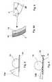
- FIGS. 3 and 4 it can be seen in FIGS. 3 and 4 to what extent the wetting angle on the surface of a toilet bowl 2 is reduced by a nanocoating.
- 3 shows a conventional surface 14 without a coating or with a known, for example PTFE-coated toilet bowl.
- a drop of water or faecal matter 13 is located on the surface 14 of the toilet bowl 2.
- the wetting angle 13A is relatively large and thus the drop 13 adheres to the surface 14.
- the surface 14 is provided with a nano-coating 15.
- the nano-coating 15 is produced using nano-technology and applied to the surface 14. It is shown in more detail in the following FIG. 5 and its production is described.
- the nanocoating 15 has a layer thickness in the nanometer range.
- Nano-technology creates orderly surfaces, which means that when the surface is wetted, the wetting angle 13B approaches 0 ° and thus the best possible non-stick coating is created.
- the adhesion of the water or. Faecal particles 13 on the nano-coating 15 are inhibited or at least significantly reduced.
- the water or faecal droplet 13 does not adhere to such a surface if the toilet bowl 2 according to FIGS. 1 and 2 is coated with it.
- the fakalie parts or drops 13 fall by gravity into the preferably also coated outlet 2B of the toilet bowl 2 and are then sucked off by the action of the vacuum via the collecting line 4 into the collecting container 5.
- a toilet bowl 2 according to the invention is shown as a detail in FIG. 5.
- the nano-layer 15 on the surface of the toilet bowl 2 can be seen in a sectional illustration.
- the toilet bowl is preferably made of stainless steel, since on the one hand corrosion is prevented and on the other hand this material is not brittle. Plastic materials can also be used for the toilet bowl and other components of the toilet system.
- the toilet bowl 2 is provided with a base layer 16 in the embodiment shown. Such a layer 16 may possibly be necessary if applying the nano-layer 15 to the base material of the toilet bowl causes problems - for example insufficient adhesion or excessive roughness - and the nano-layer 15 can be better produced on the base layer 16.
- a pretreatment of the surface to be coated is provided in the toilet bowl.
- the surface must be sanded to achieve a surface roughness in the range of ⁇ 100 nm and a center roughness in the range of ⁇ 10 nm.
- the surface is cleaned with an organic solvent and / or by means of ultrasound.
- Metals or elements of the fourth main group of the periodic table in particular Cr, Ti, Mn, Ni, Ta, Al, V, W, Co, Be, Zr, Hf, Nb, Mo, C, are preferably suitable as the material for producing the nano layer 15.
- the nano-layer 15 from a compound with a covalent bond character, such as B 4 C, SiC, BN, Si 3 N 4 or MoS 2 .
- the layer 15 can also be produced from a compound with an ionic binding character, such as Al 2 O 3 or ZrO 2 or BeO. Furthermore, the nano-layer 15 can also be formed from a sialon compound or from polymers.
- a non-stick coating based on inorganic-organic can by known coating technologies, such as Dipping, spraying or spinning, followed by curing with UV radiation and / or thermal influence can be achieved, with nanoparticles achieve desired non-stick properties.
- the nano-layer 15 With the possible methods for producing the nano-layer 15, it is essential that the nano-layer 15 is made rather soft and non-brittle. This prevents 2 parts of the nano-layer 15 from flaking off the toilet bowl.
- Magnetron sputter technology is provided as the preferred manufacturing method.
- This technique known to those skilled in the art, belongs to the group of cathode sputtering processes in which the coating is applied in vacuo and a solid base is provided with metallic or non-metallic layers.
- the coating material on the cathodes is atomized by bombardment with gas ions in a gas atmosphere and is deposited as a layer on the surface of the toilet bowl.
- the ions ensure that the upper atomic layers of the coating material are converted into the gaseous state by pulse exchange.
- the coating material now in the gaseous state then deposits on the surface to be coated.
- the nano-coating is the Toilet bowl 2 has been described in more detail. It is possible that with suitable application methods also other system components, which with Faeces or contaminants come into contact with a nano-layer be provided.
- the header 4 is coated or at least parts of the collecting line 4, such as branches, are conceivable, to keep the toilet system as easy to clean as possible hold.
Landscapes
- Engineering & Computer Science (AREA)
- Health & Medical Sciences (AREA)
- Life Sciences & Earth Sciences (AREA)
- Hydrology & Water Resources (AREA)
- Public Health (AREA)
- Water Supply & Treatment (AREA)
- Aviation & Aerospace Engineering (AREA)
- Sanitary Device For Flush Toilet (AREA)
- Vehicle Waterproofing, Decoration, And Sanitation Devices (AREA)
- Agricultural Chemicals And Associated Chemicals (AREA)
- Non-Flushing Toilets (AREA)
Abstract
Description
So ist aus DE 42 01 986 eine Vakuumtoilette bekannt, die im wesentlichen ausgestattet ist mit einer Auslöseeinrichtung, einem Spülwasserventil und einem Absaugventil, welches in einer Verbindungsleitung zwischen Toilettenbecken und Sammelbehälter angeordnet ist. Mittels Steuereinrichtungen wird die Spülflüssigkeit nach Betätigung der Auslösevorrichtung dem Toilettenbecken zugeführt, anschließend öffnet das Absaugventil und die im Toilettenbecken enthaltenen Verunreinigungen werden zusammen mit der Spülflüssigkeit in den Sammelbehälter geleitet.
- Fig. 1
- eine erste Ausführungsform eines Vakuumtoilettensystems mit einer erfindungsgemäßen Toilettenschüssel,
- Fig. 2
- eine zweite Ausführungsform eines Vakuumtoilettensystems mit einer erfindungsgemäßen Toilettenschüssel,
- Fign. 3 und 4
- eine Darstellung der unterschiedlichen Benetzungswinkel an der Oberfläche einer Toilettenschüssel in Abhängigkeit von der Oberflächenbeschichtung und
- Fig. 5
- eine erfindungsgemäße Toilettenschüssel als Einzelheit mit einer Darstellung der Beschichtung.
Die weiteren Systemkomponenten sind identisch mit der Ausführungsform des Toilettensystems gemäß Fig. 1. Durch den Wegfall der Spülwasserzuführung ist eine vereinfachte Steuerung und damit eine Vereinfachung der Steuereinheit 12 erreicht. Für das Abführen der in der Toilettenschüssel 2 angesammelten Abfallprodukte ist nur noch das Öffnen und Schließen des Abwasserventils 3 notwendig und der Transport des Abfallproduktes wird zum größten Teil mittels der Absaugluft des innerhalb des Toilettensystems herrschenden Vakuums erreicht. Darüber hinaus wirkt sich aufgrund der minimalen Haftung von Verunreinigungen an der Oberfläche der Toilettenschüssel 2 die Schwerkraft vorteilhaft aus und nach dem Abtransport des Abfallproduktes ist die Toilettenschüssel 2 auch ohne Spülung sauber.
In Fig. 3 ist eine herkömmliche Oberfläche 14 ohne Beschichtung oder mit einer bekannten, beispielsweise PTFE-beschichteten Toilettenschüssel gezeigt. Ein Wasser- bzw. Fäkalientropfen 13 befindet sich auf der Oberfläche 14 der Toilettenschüssel 2. Der Benetzungswinkel 13A ist relativ groß und somit ist eine Haftung des Tropfens 13 auf der Oberfläche 14 gegeben.
In Fig. 4 ist die Oberfläche 14 mit einer Nanobeschichtung 15 versehen. Die Nanobeschichtung 15 wird mittels Nano-Technologie erzeugt und auf der Oberfläche 14 aufgebracht. Sie wird näher in der nachfolgenden Fig. 5 gezeigt und deren Herstellung beschrieben. Die Nanobeschichtung 15 besitzt eine Schichtdicke im Nanometer-Bereich. Mittels der Nano-Technologie entstehen geordnete Oberflächen, die zur Folge haben, dass bei Benetzung der Oberfläche der Benetzungswinkel 13B gegen 0° geht und somit eine bestmöglich erreichbare Antihaftbeschichtung entsteht. Die Adhäsion der Wasser-bzw. Fäkalienteilchen 13 an der Nanobeschichtung 15 ist gehemmt oder zumindest wesentlich reduziert. Der Wasser- bzw. Fäkalientropfen 13 haftet nicht an einer solchen Oberfläche, wenn die Toilettenschüssel 2 gemäß der Figuren 1 und 2 damit beschichtet ist. Die Fakalienteile bzw. -tropfen 13 fallen durch die Schwerkraft in den vorzugsweise ebenfalls beschichteten Auslauf 2B der Toilettenschüssel 2 und werden dann durch die Einwirkung des Vakuums über die Sammelleitung 4 in den Sammelbehälter 5 abgesaugt.
Die Toilettenschüssel 2 ist in der gezeigten Ausführungsform mit einer Grundschicht 16 versehen. Eine solche Schicht 16 kann möglicherweise notwendig sein, wenn ein Aufbringen der Nanoschicht 15 auf das Grundmaterial der Toilettenschüssel Probleme - z.B. keine ausreichende Haftung bzw. zu hohe Rauhigkeit - mit sich bringt und die Nanoschicht 15 auf der Grundschicht 16 besser erzeugt werden kann.
Alternativ dazu oder auch unterhalb der Grundschicht 16 ist in einer bevorzugten Ausführung eine Vorbehandlung der zu beschichtenden Oberfläche im Toilettenbecken vorgesehen. Die Oberfläche muss dafür geschliffen werden, um eine Oberflächenrauhigkeit im Bereich von < 100 nm und eine Mittenrauhigkeit im Bereich von < 10nm zu erreichen. Abschließend wird die Oberfläche mit einem organischen Lösungsmittel und/oder mittels Ultraschalleinwirkung gereinigt.
Im folgenden wird das Aufbringen der Nanoschicht 15 auf eine Toilettenschüssel 2 näher beschrieben.
Als Material zur Herstellung der Nanoschicht 15 eignen sich vorzugsweise Metalle oder Elemente der vierten Hauptgruppe des Periodensystems, insbesondere Cr, Ti, Mn, Ni, Ta, Al, V, W, Co, Be, Zr, Hf, Nb, Mo, C, Si, Ge oder Sn, oder Verbindungen mit den genannten Elementen. Es ist möglich, Verbindungen mit metallischen Bindungscharakter, insbesondere Karbide wie MC sowie Sekundärkarbide M2C, M3C, M6C, M7C, M23C6 zu verwenden, wobei hier das M als ein Metall oder für eine intermetallische Metallgruppe steht. Es ist weiterhin möglich, Nitride der Struktur MN oder Boride der Struktur MB zu verwenden, wobei das M wiederum für Metall steht.
Desweiteren kann die Nanoschicht 15 auch aus einer Sialon-Verbindung oder aus Polymeren ausgebildet sein.
Mögliche Herstellungsverfahren sind z.B.:
- Kathodenzerstäubung
- Ionenimplantierung
- Sputtertechnik (Plasmastrahlquelle, Magnetronzerstäubung, RFDiodenzerstäubung)
- Gasphasenabscheidung (Chemical Vapor Deposition -CVD-, Atomic Layer Epitaxy ―ALE-, Chemical Beam Epitaxy ― CBE-)
- PACVD-(Plasma assisted Chemical Vapor Deposition) Verfahren
- PVD- (Physical Vapor Deposition) Verfahren
Als bevorzugtes Herstellungsverfahren ist die Magnetron-Sputter-Technik vorgesehen. Diese, dem Fachmann bekannte Technik gehört zur Verfahrensgruppe der Kathodenzerstäubung, bei der im Vakuum die Beschichtung aufgebracht und ein fester Untergrund mit metallischen bzw. nichtmetallischen Schichten versehen wird. Das Beschichtungsmaterial auf den Kathoden wird durch Beschuß mit Gasionen in einer Gasatmosphäre zerstäubt und schlägt sich auf der Toilettenschüssel-Oberfläche als Schicht nieder. Die lonen sorgen dafür, dass die oberen Atomschichten aus dem Beschichtungsmaterial durch Impulsaustausch in den gasförmigen Zustand überführt werden. Das nun im gasförmigen Zustand vorliegende Beschichtungsmaterial scheidet sich dann auf der zu beschichtenden Fläche ab.
Claims (15)
- Toilettensystem (1;20), insbesondere für Verkehrsmittel, wobei mindestens ein Toilettenbecken (2) vorgesehen ist, welches über ein Absaugventil (3) mit einem Sammelbehälter (5) verbunden ist, dadurch gekennzeichnet, dass zumindest teilweise die mit den abzuführenden Verunreinigungen in Kontakt kommenden Systemkomponenten mit einer Nanoschicht (15) versehen sind.
- Toilettensystem nach Anspruch 1,
dadurch gekennzeichnet, dass
die Oberfläche des Toilettenbeckens (2) zumindest in Bereichen (2A, 2B), die mit verunreinigenden Substanzen in Berührung kommen, mit der Nanoschicht (15) versehen ist. - Tollettensystem nach einem der Ansprüche 1 oder 2,
dadurch gekennzeichnet, dass
das Toilettensystem (20) ohne Spülwasserkreislauf ausgebildet ist. - Toilettensystem nach einem der Ansprüche 1 bis 3,
dadurch gekennzeichnet, dass
zumindest teilweise Absaugluft, die nach dem Öffnen des Absaugventils (3) in das Toilettenbecken (2) gelangt, zum Reinigen des Toilettenbeckens vorgesehen ist. - Toilettensystem nach einem der Ansprüche 1 bis 4, dadurch gekennzeichnet, dass
die Oberfläche des mit der Nanoschicht (15) vorgesehenen Bereichs (2A, 2B) mit einer Grundschicht (16) versehen ist, auf die die Nanoschicht (15) aufbringbar ist. - Toilettensystem nach einem der Ansprüche 1 bis 5,
dadurch gekennzeichnet, dass
die Nanoschicht (15) aus einem Metall oder einem Element der vierten Hauptgruppe des Periodensystems oder einer Verbindung mit kovalentem Bindungscharakter oder aus einer Verbindung mit ionischem Bindungscharakter oder aus einer Sialon-Verbindung oder aus einem Polymer besteht. - Toilettenbecken zur Verwendung in einem Toilettensytem gemäß der vorangegangenen Ansprüche,
dadurch gekennzeichnet, dass
das Toilettenbecken (2) zumindest bereichsweise mit der Nanoschicht (15) versehen ist, wobei die Schicht (15) alsDünne Schicht" mittels Nanotechnologie erzeugbar ist.
- Verfahren zur Herstellung eines Toilettensystems nach einem der vorangegangenen Ansprüche,
dadurch gekennzeichnet, dass
eine Beschichtung zumindest teilweise auf die mit den abzuführenden Verunreinigungen in Kontakt kommenden Bereiche (2A, 2B) der Systemkomponenten aufgebracht wird, wobei die Schicht (Nanoschicht 15) als - Verfahren nach Anspruch 8,
dadurch gekennzeichnet, dass
die Oberfläche der mit der Nanoschicht (15) vorgesehenen Bereiche (2A, 2B) der Systemkomponenten, beispielsweise des Toilettenbeckens (2), mit einer Grundschicht (16) versehen wird, auf die die Nanoschicht (15) aufgebracht wird. - Verfahren nach einem der Ansprüche 8 oder 9,
dadurch gekennzeichnet, dass
die Oberfläche der Bereiche (2A, 2B) mittels Schleifen und Reinigen vorbehandelt wird. - Verfahren nach einem der Ansprüche 8 bis 10,
dadurch gekennzeichnet, dass
die Nanoschicht (15) mittels Kathodenzerstäubung aufgebracht wird. - Verfahren nach einem der Ansprüche 8 bis 10,
dadurch gekennzeichnet, dass
zum Aufbringen der Nanoschicht (15) ein Magnetron-Sputter-Verfahren eingesetzt wird. - Verfahren nach einem der Ansprüche 8 bis 10,
dadurch gekennzeichnet, dass
die Nanoschicht (15) durch Ionenimplantieren oder Sputtertechnik oder Gasphasen-abscheidung (CVD-Prozeß, PACVD-Prozeß) oder Physical Vapor Deposition-Verfahren (PVD-Prozeß) auf die Oberfläche aufgebracht wird. - Verfahren nach einem der Ansprüche 8 bis 10,
dadurch gekennzeichnet, dass
zum Aufbringen der Nanoschicht (15) übliche Beschichtungsverfahren, wie Tauchen, Sprühen oder Schleudern, mit Einbringen von Nanopartikeln eingesetzt werden. - Verfahren nach Anspruch 14,
dadurch gekennzeichnet, dass
nach dem Beschichtungsprozess eine Härtung durch UV-Strahlung und/oder thermischen Einfluss durchgeführt wird.
Applications Claiming Priority (2)
| Application Number | Priority Date | Filing Date | Title |
|---|---|---|---|
| DE19928894A DE19928894C2 (de) | 1999-06-24 | 1999-06-24 | Toilettensystem, insbesondere für Verkehrsmittel |
| DE19928894 | 1999-06-24 |
Publications (3)
| Publication Number | Publication Date |
|---|---|
| EP1063167A2 true EP1063167A2 (de) | 2000-12-27 |
| EP1063167A3 EP1063167A3 (de) | 2002-03-20 |
| EP1063167B1 EP1063167B1 (de) | 2003-09-10 |
Family
ID=7912346
Family Applications (1)
| Application Number | Title | Priority Date | Filing Date |
|---|---|---|---|
| EP00112925A Expired - Lifetime EP1063167B1 (de) | 1999-06-24 | 2000-06-20 | Toilettensystem, insbesondere für Verkehrsmittel |
Country Status (4)
| Country | Link |
|---|---|
| EP (1) | EP1063167B1 (de) |
| AT (1) | ATE249359T1 (de) |
| DE (2) | DE19928894C2 (de) |
| ES (1) | ES2204405T3 (de) |
Cited By (3)
| Publication number | Priority date | Publication date | Assignee | Title |
|---|---|---|---|---|
| WO2004020285A1 (de) * | 2002-08-14 | 2004-03-11 | Airbus Deutschland Gmbh | Frischwassersystem eines verkehrsflugzeuges |
| US6977005B2 (en) | 1999-06-24 | 2005-12-20 | Airbus Deutschland Gmbh | Waterless vacuum toilet system for aircraft |
| CN108951786A (zh) * | 2018-08-09 | 2018-12-07 | 陈龙 | 一种便尿分离处理利用的免水冲马桶 |
Families Citing this family (2)
| Publication number | Priority date | Publication date | Assignee | Title |
|---|---|---|---|---|
| DE10100962C2 (de) * | 2001-01-11 | 2003-09-25 | Airbus Gmbh | Toiletteneinrichtung, insbesondere für Verkehrsmittel |
| CN112962503A (zh) * | 2021-02-05 | 2021-06-15 | 高晓风 | 一种建筑施工用防尘装置 |
Citations (4)
| Publication number | Priority date | Publication date | Assignee | Title |
|---|---|---|---|---|
| EP0295508A1 (de) | 1987-06-19 | 1988-12-21 | Messerschmitt-Bölkow-Blohm Gesellschaft mit beschränkter Haftung | Wassersystem für eine Sanitäreinheit insbesondere an Bord eines Flugzeuges |
| EP0363012A1 (de) | 1988-09-06 | 1990-04-11 | Metra Oy AB | Vakuumtoilettensystem |
| DE9201684U1 (de) | 1991-06-04 | 1992-04-30 | kki Handelsgesellschaft für Kunststofferzeugnisse mbH, 1000 Berlin | Toilettenanordnung zur Installation ohne festen Entsorgungsanschluß |
| DE4201986C1 (de) | 1992-01-25 | 1993-04-15 | Deutsche Airbus Gmbh, 2000 Hamburg, De |
Family Cites Families (7)
| Publication number | Priority date | Publication date | Assignee | Title |
|---|---|---|---|---|
| US3504381A (en) * | 1968-02-21 | 1970-04-07 | Davis R Dewey | Toilet bowl |
| DE8711253U1 (de) * | 1987-08-19 | 1988-02-18 | Dienst, Dieter, 6234 Hattersheim | WC-Papier-Teller |
| DE9016201U1 (de) * | 1990-11-23 | 1991-03-07 | Auschra, Michael, 1000 Berlin | Vorrichtung zur Reinhaltung von Toilettenbecken, insbesondere Flachspülbecken |
| US5604938A (en) * | 1992-04-02 | 1997-02-25 | Norcan Aircraft Corporation | Vacuum flush waste disposal system for railcars |
| DE4414051C1 (de) * | 1994-04-22 | 1995-07-06 | Dresden Ev Inst Festkoerper | Reibarmer Schichtverbund für Bauteile aus metallischen Werkstoffen |
| DE59710964D1 (de) * | 1997-09-22 | 2003-12-11 | Bob W Illy | Urinanlage aus Keramik, Glas oder Metall |
| JPH11350574A (ja) * | 1998-06-05 | 1999-12-21 | Inax Corp | 防汚性物品および防汚性物品の製造方法 |
-
1999
- 1999-06-24 DE DE19928894A patent/DE19928894C2/de not_active Expired - Fee Related
-
2000
- 2000-06-20 DE DE50003610T patent/DE50003610D1/de not_active Expired - Lifetime
- 2000-06-20 AT AT00112925T patent/ATE249359T1/de not_active IP Right Cessation
- 2000-06-20 EP EP00112925A patent/EP1063167B1/de not_active Expired - Lifetime
- 2000-06-20 ES ES00112925T patent/ES2204405T3/es not_active Expired - Lifetime
Patent Citations (4)
| Publication number | Priority date | Publication date | Assignee | Title |
|---|---|---|---|---|
| EP0295508A1 (de) | 1987-06-19 | 1988-12-21 | Messerschmitt-Bölkow-Blohm Gesellschaft mit beschränkter Haftung | Wassersystem für eine Sanitäreinheit insbesondere an Bord eines Flugzeuges |
| EP0363012A1 (de) | 1988-09-06 | 1990-04-11 | Metra Oy AB | Vakuumtoilettensystem |
| DE9201684U1 (de) | 1991-06-04 | 1992-04-30 | kki Handelsgesellschaft für Kunststofferzeugnisse mbH, 1000 Berlin | Toilettenanordnung zur Installation ohne festen Entsorgungsanschluß |
| DE4201986C1 (de) | 1992-01-25 | 1993-04-15 | Deutsche Airbus Gmbh, 2000 Hamburg, De |
Cited By (3)
| Publication number | Priority date | Publication date | Assignee | Title |
|---|---|---|---|---|
| US6977005B2 (en) | 1999-06-24 | 2005-12-20 | Airbus Deutschland Gmbh | Waterless vacuum toilet system for aircraft |
| WO2004020285A1 (de) * | 2002-08-14 | 2004-03-11 | Airbus Deutschland Gmbh | Frischwassersystem eines verkehrsflugzeuges |
| CN108951786A (zh) * | 2018-08-09 | 2018-12-07 | 陈龙 | 一种便尿分离处理利用的免水冲马桶 |
Also Published As
| Publication number | Publication date |
|---|---|
| EP1063167B1 (de) | 2003-09-10 |
| ATE249359T1 (de) | 2003-09-15 |
| DE50003610D1 (de) | 2003-10-16 |
| EP1063167A3 (de) | 2002-03-20 |
| DE19928894A1 (de) | 2001-01-04 |
| DE19928894C2 (de) | 2003-07-17 |
| ES2204405T3 (es) | 2004-05-01 |
Similar Documents
| Publication | Publication Date | Title |
|---|---|---|
| EP1690789B1 (de) | Flugzeug mit Grauwasser-Nutzungssystem | |
| EP1604898B1 (de) | Wasseraufbereitung für Luftfahrzeuge | |
| EP0704372B1 (de) | Vakuumtoilettensystem in einem Flugzeug | |
| EP0686107B1 (de) | Toilettenanlage | |
| EP3129560B1 (de) | Pneumatische kompakt-vakuumtoilette | |
| WO2000007878A1 (de) | Vakuumtoilettensystem für ein fahrzeug | |
| DE19928894C2 (de) | Toilettensystem, insbesondere für Verkehrsmittel | |
| DE3026763A1 (de) | Vakuum-spueltoilettensystem | |
| DE112014005154T5 (de) | Versatzdichtungskonfiguration für Unterdrucksysteme | |
| DE19713504C1 (de) | Vakuumtoilettensystem und Verfahren zum Betreiben und zum Beseitigen von Verstopfungen | |
| EP3592622A1 (de) | Abwassersystem für fahrzeuge | |
| EP3015367A1 (de) | Entsorgungsvorrichtung für ein flugzeug sowie flugzeug mit der entsorgungsvorrichtung | |
| EP0986679B1 (de) | Toilettenanlage mit unterdruckabsaugung | |
| WO2004020285A1 (de) | Frischwassersystem eines verkehrsflugzeuges | |
| DE10065156C1 (de) | Verfahren zum Herstellen von mindestens zwei oberflächenmäßig unterschiedlichen Typen von Handhaben aus Kunststoffmaterial | |
| DE102020120913A1 (de) | Spülkasten für eine Sanitäreinrichtung | |
| DE102020112602A1 (de) | Verfahren zur Beschichtung eines Sanitärartikels, Verwendung von Nanopartikeln und Sanitärartikel mit einer beschichteten Oberfläche | |
| DE29711739U1 (de) | Vorrichtung zur Aufbereitung von ggf. auch kontaminierten in Sanitäranlagen anfallenden Schlämmen | |
| EP4187028A1 (de) | Filtereinrichtung für einen spülkasten und spülkasten für eine sanitäreinrichtung | |
| DE102023134610A1 (de) | Vakuumtoilettensystem | |
| DE102024121339A1 (de) | Vorrichtung zum Beschichten mindestens eines Objekts, Anlage zum Herstellen und/oder Behandeln mindestens eines Behälters und Verfahren zum Entfernen von Ablagerungen | |
| DE102018112083B4 (de) | Vorrichtung zur Behandlung von Wasser, deren Verwendung und ein Verfahren zur Behandlung von Wasser in einer wasserführenden Anlage | |
| DE69415146T2 (de) | Wasserklosettvorrichtung | |
| DE202020106645U1 (de) | Vakuumtoilette | |
| DE102021125410A1 (de) | Filtereinrichtung für einen Spülkasten und Spülkasten für eine Sanitäreinrichtung |
Legal Events
| Date | Code | Title | Description |
|---|---|---|---|
| PUAI | Public reference made under article 153(3) epc to a published international application that has entered the european phase |
Free format text: ORIGINAL CODE: 0009012 |
|
| AK | Designated contracting states |
Kind code of ref document: A2 Designated state(s): AT BE CH CY DE DK ES FI FR GB GR IE IT LI LU MC NL PT SE |
|
| AX | Request for extension of the european patent |
Free format text: AL;LT;LV;MK;RO;SI |
|
| PUAL | Search report despatched |
Free format text: ORIGINAL CODE: 0009013 |
|
| RAP1 | Party data changed (applicant data changed or rights of an application transferred) |
Owner name: AIRBUS DEUTSCHLAND GMBH |
|
| AK | Designated contracting states |
Kind code of ref document: A3 Designated state(s): AT BE CH CY DE DK ES FI FR GB GR IE IT LI LU MC NL PT SE |
|
| AX | Request for extension of the european patent |
Free format text: AL;LT;LV;MK;RO;SI |
|
| RIC1 | Information provided on ipc code assigned before grant |
Free format text: 7B 64D 11/02 A, 7E 03F 1/00 B, 7E 03D 11/02 B |
|
| 17P | Request for examination filed |
Effective date: 20020316 |
|
| 17Q | First examination report despatched |
Effective date: 20020715 |
|
| AKX | Designation fees paid |
Free format text: AT BE CH CY DE DK ES FI FR GB GR IE IT LI LU MC NL PT SE |
|
| GRAH | Despatch of communication of intention to grant a patent |
Free format text: ORIGINAL CODE: EPIDOS IGRA |
|
| GRAH | Despatch of communication of intention to grant a patent |
Free format text: ORIGINAL CODE: EPIDOS IGRA |
|
| GRAA | (expected) grant |
Free format text: ORIGINAL CODE: 0009210 |
|
| AK | Designated contracting states |
Kind code of ref document: B1 Designated state(s): AT BE CH CY DE DK ES FI FR GB GR IE IT LI LU MC NL PT SE |
|
| PG25 | Lapsed in a contracting state [announced via postgrant information from national office to epo] |
Ref country code: FI Free format text: LAPSE BECAUSE OF FAILURE TO SUBMIT A TRANSLATION OF THE DESCRIPTION OR TO PAY THE FEE WITHIN THE PRESCRIBED TIME-LIMIT Effective date: 20030910 Ref country code: NL Free format text: LAPSE BECAUSE OF FAILURE TO SUBMIT A TRANSLATION OF THE DESCRIPTION OR TO PAY THE FEE WITHIN THE PRESCRIBED TIME-LIMIT Effective date: 20030910 Ref country code: IE Free format text: LAPSE BECAUSE OF FAILURE TO SUBMIT A TRANSLATION OF THE DESCRIPTION OR TO PAY THE FEE WITHIN THE PRESCRIBED TIME-LIMIT Effective date: 20030910 Ref country code: CY Free format text: LAPSE BECAUSE OF FAILURE TO SUBMIT A TRANSLATION OF THE DESCRIPTION OR TO PAY THE FEE WITHIN THE PRESCRIBED TIME-LIMIT Effective date: 20030910 |
|
| REG | Reference to a national code |
Ref country code: GB Ref legal event code: FG4D Free format text: NOT ENGLISH |
|
| REG | Reference to a national code |
Ref country code: CH Ref legal event code: EP |
|
| REF | Corresponds to: |
Ref document number: 50003610 Country of ref document: DE Date of ref document: 20031016 Kind code of ref document: P |
|
| REG | Reference to a national code |
Ref country code: IE Ref legal event code: FG4D Free format text: GERMAN |
|
| PG25 | Lapsed in a contracting state [announced via postgrant information from national office to epo] |
Ref country code: SE Free format text: LAPSE BECAUSE OF FAILURE TO SUBMIT A TRANSLATION OF THE DESCRIPTION OR TO PAY THE FEE WITHIN THE PRESCRIBED TIME-LIMIT Effective date: 20031210 Ref country code: GR Free format text: LAPSE BECAUSE OF FAILURE TO SUBMIT A TRANSLATION OF THE DESCRIPTION OR TO PAY THE FEE WITHIN THE PRESCRIBED TIME-LIMIT Effective date: 20031210 Ref country code: DK Free format text: LAPSE BECAUSE OF FAILURE TO SUBMIT A TRANSLATION OF THE DESCRIPTION OR TO PAY THE FEE WITHIN THE PRESCRIBED TIME-LIMIT Effective date: 20031210 |
|
| PG25 | Lapsed in a contracting state [announced via postgrant information from national office to epo] |
Ref country code: PT Free format text: LAPSE BECAUSE OF FAILURE TO SUBMIT A TRANSLATION OF THE DESCRIPTION OR TO PAY THE FEE WITHIN THE PRESCRIBED TIME-LIMIT Effective date: 20031218 |
|
| GBT | Gb: translation of ep patent filed (gb section 77(6)(a)/1977) |
Effective date: 20031220 |
|
| NLV1 | Nl: lapsed or annulled due to failure to fulfill the requirements of art. 29p and 29m of the patents act | ||
| REG | Reference to a national code |
Ref country code: IE Ref legal event code: FD4D |
|
| REG | Reference to a national code |
Ref country code: ES Ref legal event code: FG2A Ref document number: 2204405 Country of ref document: ES Kind code of ref document: T3 |
|
| PG25 | Lapsed in a contracting state [announced via postgrant information from national office to epo] |
Ref country code: AT Free format text: LAPSE BECAUSE OF NON-PAYMENT OF DUE FEES Effective date: 20040620 Ref country code: LU Free format text: LAPSE BECAUSE OF NON-PAYMENT OF DUE FEES Effective date: 20040620 |
|
| PG25 | Lapsed in a contracting state [announced via postgrant information from national office to epo] |
Ref country code: MC Free format text: LAPSE BECAUSE OF NON-PAYMENT OF DUE FEES Effective date: 20040630 Ref country code: CH Free format text: LAPSE BECAUSE OF NON-PAYMENT OF DUE FEES Effective date: 20040630 Ref country code: BE Free format text: LAPSE BECAUSE OF NON-PAYMENT OF DUE FEES Effective date: 20040630 Ref country code: LI Free format text: LAPSE BECAUSE OF NON-PAYMENT OF DUE FEES Effective date: 20040630 |
|
| ET | Fr: translation filed | ||
| PLBE | No opposition filed within time limit |
Free format text: ORIGINAL CODE: 0009261 |
|
| STAA | Information on the status of an ep patent application or granted ep patent |
Free format text: STATUS: NO OPPOSITION FILED WITHIN TIME LIMIT |
|
| 26N | No opposition filed |
Effective date: 20040614 |
|
| BERE | Be: lapsed |
Owner name: *AIRBUS DEUTSCHLAND G.M.B.H. Effective date: 20040630 |
|
| REG | Reference to a national code |
Ref country code: CH Ref legal event code: PL |
|
| REG | Reference to a national code |
Ref country code: ES Ref legal event code: PC2A Owner name: AIRBUS OPERATIONS GMBH Effective date: 20110930 |
|
| REG | Reference to a national code |
Ref country code: FR Ref legal event code: CD Owner name: AIRBUS OPERATIONS GMBH Effective date: 20111118 |
|
| PGFP | Annual fee paid to national office [announced via postgrant information from national office to epo] |
Ref country code: GB Payment date: 20140618 Year of fee payment: 15 |
|
| PGFP | Annual fee paid to national office [announced via postgrant information from national office to epo] |
Ref country code: ES Payment date: 20140627 Year of fee payment: 15 Ref country code: DE Payment date: 20140619 Year of fee payment: 15 |
|
| PGFP | Annual fee paid to national office [announced via postgrant information from national office to epo] |
Ref country code: FR Payment date: 20140619 Year of fee payment: 15 |
|
| PGFP | Annual fee paid to national office [announced via postgrant information from national office to epo] |
Ref country code: IT Payment date: 20140630 Year of fee payment: 15 |
|
| REG | Reference to a national code |
Ref country code: DE Ref legal event code: R119 Ref document number: 50003610 Country of ref document: DE |
|
| PG25 | Lapsed in a contracting state [announced via postgrant information from national office to epo] |
Ref country code: IT Free format text: LAPSE BECAUSE OF NON-PAYMENT OF DUE FEES Effective date: 20150620 |
|
| GBPC | Gb: european patent ceased through non-payment of renewal fee |
Effective date: 20150620 |
|
| REG | Reference to a national code |
Ref country code: FR Ref legal event code: ST Effective date: 20160229 |
|
| PG25 | Lapsed in a contracting state [announced via postgrant information from national office to epo] |
Ref country code: GB Free format text: LAPSE BECAUSE OF NON-PAYMENT OF DUE FEES Effective date: 20150620 Ref country code: DE Free format text: LAPSE BECAUSE OF NON-PAYMENT OF DUE FEES Effective date: 20160101 |
|
| PG25 | Lapsed in a contracting state [announced via postgrant information from national office to epo] |
Ref country code: FR Free format text: LAPSE BECAUSE OF NON-PAYMENT OF DUE FEES Effective date: 20150630 |
|
| REG | Reference to a national code |
Ref country code: ES Ref legal event code: FD2A Effective date: 20160801 |
|
| PG25 | Lapsed in a contracting state [announced via postgrant information from national office to epo] |
Ref country code: ES Free format text: LAPSE BECAUSE OF NON-PAYMENT OF DUE FEES Effective date: 20150621 |