EP1063192A2 - Dispositif pour contrôler les éléments soufflants dans le dispositif de sortie d'une machine à imprimer - Google Patents
Dispositif pour contrôler les éléments soufflants dans le dispositif de sortie d'une machine à imprimer Download PDFInfo
- Publication number
- EP1063192A2 EP1063192A2 EP00112934A EP00112934A EP1063192A2 EP 1063192 A2 EP1063192 A2 EP 1063192A2 EP 00112934 A EP00112934 A EP 00112934A EP 00112934 A EP00112934 A EP 00112934A EP 1063192 A2 EP1063192 A2 EP 1063192A2
- Authority
- EP
- European Patent Office
- Prior art keywords
- elements
- actuators
- blowing
- selection
- setpoint
- Prior art date
- Legal status (The legal status is an assumption and is not a legal conclusion. Google has not performed a legal analysis and makes no representation as to the accuracy of the status listed.)
- Ceased
Links
Images



Classifications
-
- B—PERFORMING OPERATIONS; TRANSPORTING
- B65—CONVEYING; PACKING; STORING; HANDLING THIN OR FILAMENTARY MATERIAL
- B65H—HANDLING THIN OR FILAMENTARY MATERIAL, e.g. SHEETS, WEBS, CABLES
- B65H29/00—Delivering or advancing articles from machines; Advancing articles to or into piles
- B65H29/24—Delivering or advancing articles from machines; Advancing articles to or into piles by air blast or suction apparatus
- B65H29/245—Air blast devices
- B65H29/246—Air blast devices acting on stacking devices
- B65H29/247—Air blast devices acting on stacking devices blowing on upperside of the sheet
-
- B—PERFORMING OPERATIONS; TRANSPORTING
- B65—CONVEYING; PACKING; STORING; HANDLING THIN OR FILAMENTARY MATERIAL
- B65H—HANDLING THIN OR FILAMENTARY MATERIAL, e.g. SHEETS, WEBS, CABLES
- B65H2515/00—Physical entities not provided for in groups B65H2511/00 or B65H2513/00
- B65H2515/20—Volume; Volume flow
-
- B—PERFORMING OPERATIONS; TRANSPORTING
- B65—CONVEYING; PACKING; STORING; HANDLING THIN OR FILAMENTARY MATERIAL
- B65H—HANDLING THIN OR FILAMENTARY MATERIAL, e.g. SHEETS, WEBS, CABLES
- B65H2551/00—Means for control to be used by operator; User interfaces
- B65H2551/10—Command input means
- B65H2551/15—Push buttons; Keyboards
-
- B—PERFORMING OPERATIONS; TRANSPORTING
- B65—CONVEYING; PACKING; STORING; HANDLING THIN OR FILAMENTARY MATERIAL
- B65H—HANDLING THIN OR FILAMENTARY MATERIAL, e.g. SHEETS, WEBS, CABLES
- B65H2551/00—Means for control to be used by operator; User interfaces
- B65H2551/10—Command input means
- B65H2551/18—Graphical interactive displays; Mouses; Touchscreens
-
- B—PERFORMING OPERATIONS; TRANSPORTING
- B65—CONVEYING; PACKING; STORING; HANDLING THIN OR FILAMENTARY MATERIAL
- B65H—HANDLING THIN OR FILAMENTARY MATERIAL, e.g. SHEETS, WEBS, CABLES
- B65H2801/00—Application field
- B65H2801/03—Image reproduction devices
- B65H2801/21—Industrial-size printers, e.g. rotary printing press
Definitions
- a control and regulating device of a sheet delivery of a printing press in which the adjusting elements are automatically adapted to the changing operating conditions after a single setting according to a predetermined program.
- the so-called upper air is adjusted by means of a large number of fans via the sheet falling into the delivery. These fans are intended to ensure that the sheets are deposited properly Despite this complex control and regulating device, it always happens that a sheet in the delivery leaves the desired conveyor line and collides with the sheet guide parts or other machine elements.
- the delivery of the sheets must therefore be monitored by the delivery staff and the correct setting values for the fans have to be empirically corrected.
- the speed of the fans is set in groups using a potentiometer. After switching off the printing press, only the last set value can be reproduced by the respective potentiometer setting.
- the invention is therefore based on the object, the adjustability of the Make fans as flexible as possible and still a good one To ensure overview and manageability for the operating personnel.
- the object is achieved in that the only Control of the blowing elements trained control unit individually with each Actuator of a blowing element is connected, by actuating a Selection element of an input unit connected to the control unit or several blowing elements can be selected and then by means of one Setpoint setting element the actuators of the blow elements selected in this way the setpoint can be specified at the same time.
- the advantage of the invention is that the controls for Fan setting reduced to a manageable level for the printer be and still any combination of the to be controlled Blowing elements is possible. Due to this clear design of the The input unit is quick and easy handling of the fan control guaranteed. Due to this design of the input unit, the The operator of the fan control only needs to press two input elements to achieve a desired setting.
- the advantage of free division of the Fan is that the operator controls the fan accordingly the format and material of the substrate, its color assignment and can adapt to the environmental conditions.
- Each selection element is advantageously invariably a Blower element controlling actuator assigned, whereby the setting the blowing elements are designed to be very sensitive and flexible.
- the successive actuation several selection elements that are permanently assigned to the blowing elements Actuators selected, which then have the same setpoint using the Setpoint specification element is predetermined.
- a group of actuators is assigned to each selection element, each actuator actuating a different blowing element. This significantly reduces the number of selection elements.
- the group of actuators assigned to the selection element can be combined as desired.
- the input unit communicates with a separate fan control, in which, from the commands entered, the setpoints for the Blower elements controlling actuators are generated.
- the Fan control unit with a central control device of the printing press connected, which has a memory in which the respectively selected Configuration of the blow elements and the set associated setpoints can be saved.
- each selection and / or Setpoint setting element arranged on the respective element Display element can be activated.
- the selected actuators displayable.
- the input unit is advantageously together with the Display device arranged on the boom of the printing press.
- FIG 1 the structure of a boom 1 is a schematic Sheet offset printing machine shown.
- the one of those not shown Printing units of the printing press coming printed sheet 2 is on Boom 1 is gripped by grippers 3 and guided by suction wheels 4.
- the sheet 2 is on a sheet stack 6 filed.
- Above the sheet 2 falling onto the sheet stack 6 a large number of fans 7n, of which only three for the sake of clarity Fans 71, 72, 73 are shown, distributed so that almost the entire Surface of the sheet 2 sliding on the sheet stack 6 through the fans 7n can be influenced in a targeted manner.
- the fan 71 generates upper air, whereby the storage of the sheet 2 is targeted being affected.
- the bow 2 is properly and without Damage deposited on the sheet stack 6.
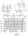
- the fans 7n are controlled with a fan controller as they are is shown in principle in Figure 2.
- This fan control consists of a Fan control device 8, which with a plurality of servomotors 9n connected is. Each servomotor 9n controls one designed as a fan Fan 7n on. In the present example, 33 fans are above the sheet stack 6 distributed. Accordingly, 8 servomotors are used by the fan control device 901 to 933 controlled, a computing unit 10 of the Fan control device 8 via a motor interface 11 with the individual Servomotors 901 to 933 is connected.
- the computing unit 10 is connected via a second interface 12 and a data line 13 with a microprocessor 14 containing Input unit 15 connected.
- the data line 13 leads through a third Interface 16 of the input unit 15 to the microprocessor 14, which with an operator interface 17 is connected.
- connection between the fan control device 8 and a central control unit 18 of the printing press which one with a Computing unit 23 has connected storage unit 19.
- the fan control device 8 and the central control unit 18 communicate the printing press with each other via a further data line 20 between an interface 21 of the fan control device 8 and one Interface 22 of the central control unit 18 extends, the Interface 22 of the control unit 18 with the computing unit 23 of the Control unit 18 is connected.
- the data lines 13 and 20 can for the sake of simplicity, preferably through the data bus of the printing press a CAN bus.
- FIG. 3 shows the user interface 17 of the input unit 15.
- the input unit 15 has a plurality of keys Mn on.
- Each servomotor 901 ... 933 shown in FIG. 2 is a key Mn assigned.
- Various function keys Fm are positioned below the selection keys Mn assigned to the servomotors 901 to 933.
- two control controls 25 and 26 for setting the setpoint for the servomotors 901 to 933 of the fans 7n are possible.
- Such control elements 25, 26 are identified by the symbols + and -.
- All servomotors 901 to 933 can be operated simultaneously via an operating element 28 can be called, which the operator of the system in the input effort Individual cases made considerably easier.
- the user interface 17 of the input unit 15 is from a printer actuated, which the sheet deposit on the boom 1 of the printing press observed.
- the sheet thickness, the color assignment of the incoming sheet 2 and the operating parameters the printing machine becomes the air flow generated by various fans 7n by specifying a setpoint for the one belonging to the respective fan 7n Actuator 901 to 933 set differently to ensure correct storage to ensure the sheet 2 on the sheet stack 6.
- the operator has the option of using any actuator 901 through 933 Actuation of the actuator 901 to 933 of the fan 7n permanently assigned Activate selection key Mn. After preselecting the fan 7n, the lights up on the selection key Mn arranged LED 24n for visual display, see above that the operator knows which fan 7n should be activated. After that the setpoint for the corresponding actuator 901 to 933 by the Controls 25 and 26 set. It can be from a setpoint 0 can be assumed. But there is also the possibility that the Microprocessor 14 based on its program a setpoint of for example, preset 40%. Based on this value, the desired setpoint is verified with the aid of control elements 25, 26 become.
- the input unit 15 described thus offers the possibility of Individual control of the individual actuators 901 to 933. But it can also several fans 7n by a successive actuation of the corresponding selection buttons Mn can be selected, the corresponding actuators 901 to 933 then by Control controls 25 and / or 26 the same setpoint is specified.
- the microprocessor 14 After the pre-selection of the servomotor 901 to 933 and input of the common setpoint, the microprocessor 14 is informed of the input unit 15 by actuating the command completion key 27 that the command input has ended. The microprocessor 14 then prepares the commands entered by the individual keys Mn or the group preselection key Fm and the control elements 25, 26 and forwards them via the data line 13 to the fan control device 8. The arithmetic unit 10 of the fan control device 8 converts the target values entered into the input unit 15 for the individual servomotors 901 to 933 of the fans 7n into corresponding control signals.
- this data is stored in the Storage unit 19 of the central control unit 18 of the printing press filed.
- a further user interface 29 of the input unit 15 is provided in a second exemplary embodiment shown in FIG. 4, which permits free allocation of fans to the group selection function elements Fm.
- the function keys F1 to F7 acting as selection keys can be freely assigned on the user interface 29 of the input unit 15.
- the user interface 29 also takes place the setting of the setpoint of the selected fans 7n using the Controls 25, 26.
- the fan groups are freely classified by operating the control center control unit 33 as follows: By pressing a function key Fm (not shown), for example F1, the microprocessor 14 is signaled that a new fan assignment is to be put together. With the help of the cursor keys 34, 35, 36, 37, the selected servomotors, for example M12, are displayed on the display device 30. The selected servomotor 901 to 933 for the group selection function key F1 is activated with the control operating key 43. A corresponding deactivation takes place via the control operating element 44. The fan group, which is characterized by the selection function key F2, is then put together in the same way as was described in connection with the selection function key F1.
- the actuators 901 to 933 in associated with the respective selection key Fm different colors or shades of gray on the display device 30 displayed.
- the selection of the groups of servomotors 901 to 933 assigned to the individual selection function keys Fm can be stored with the print job in the storage unit 19 of the central control unit 18 of the printing press.
- the last job set always remains, unless a different group selection is desired in the new job.
- This new group selection can be loaded with the setting of the new print job.
- the actuators 901 to 933 can be activated as desired or deactivated and so the composition of the fan groups depending on Necessity to be changed without the additional controls for it are necessary.
Landscapes
- Engineering & Computer Science (AREA)
- Mechanical Engineering (AREA)
- Inking, Control Or Cleaning Of Printing Machines (AREA)
- Supply, Installation And Extraction Of Printed Sheets Or Plates (AREA)
- Delivering By Means Of Belts And Rollers (AREA)
- Pile Receivers (AREA)
Applications Claiming Priority (2)
| Application Number | Priority Date | Filing Date | Title |
|---|---|---|---|
| DE29911172U | 1999-06-26 | ||
| DE29911172U DE29911172U1 (de) | 1999-06-26 | 1999-06-26 | Einrichtung zur Steuerung der Blaselemente am Ausleger einer Druckmaschine |
Publications (2)
| Publication Number | Publication Date |
|---|---|
| EP1063192A2 true EP1063192A2 (fr) | 2000-12-27 |
| EP1063192A3 EP1063192A3 (fr) | 2002-06-05 |
Family
ID=8075341
Family Applications (1)
| Application Number | Title | Priority Date | Filing Date |
|---|---|---|---|
| EP00112934A Ceased EP1063192A3 (fr) | 1999-06-26 | 2000-06-20 | Dispositif pour contrôler les éléments soufflants dans le dispositif de sortie d'une machine à imprimer |
Country Status (3)
| Country | Link |
|---|---|
| EP (1) | EP1063192A3 (fr) |
| JP (1) | JP3281359B2 (fr) |
| DE (1) | DE29911172U1 (fr) |
Cited By (3)
| Publication number | Priority date | Publication date | Assignee | Title |
|---|---|---|---|---|
| US7137750B2 (en) | 2001-01-10 | 2006-11-21 | Seiko Epson Corporation | Recording apparatus |
| DE102007052381A1 (de) * | 2007-10-31 | 2009-05-07 | Heidelberger Druckmaschinen Ag | Anzeigevorrichtung für Bedruckstoff verarbeitende Maschinen |
| US11660774B2 (en) * | 2016-12-23 | 2023-05-30 | Bobst (Shanghai) Ltd | Holding device for a workstation of a forming machine |
Families Citing this family (1)
| Publication number | Priority date | Publication date | Assignee | Title |
|---|---|---|---|---|
| JP6167555B2 (ja) * | 2013-02-21 | 2017-07-26 | 株式会社リコー | シート後処理装置、画像形成システム |
Family Cites Families (1)
| Publication number | Priority date | Publication date | Assignee | Title |
|---|---|---|---|---|
| US4643414A (en) * | 1984-04-07 | 1987-02-17 | Miller-Johannisberg Druckmaschinen Gmbh | Sheet-delivery control and regulating apparatus |
-
1999
- 1999-06-26 DE DE29911172U patent/DE29911172U1/de not_active Expired - Lifetime
-
2000
- 2000-06-20 EP EP00112934A patent/EP1063192A3/fr not_active Ceased
- 2000-06-23 JP JP2000190121A patent/JP3281359B2/ja not_active Expired - Lifetime
Cited By (5)
| Publication number | Priority date | Publication date | Assignee | Title |
|---|---|---|---|---|
| US7137750B2 (en) | 2001-01-10 | 2006-11-21 | Seiko Epson Corporation | Recording apparatus |
| US7204653B2 (en) | 2001-01-10 | 2007-04-17 | Seiko Epson Corporation | Recording apparatus |
| DE102007052381A1 (de) * | 2007-10-31 | 2009-05-07 | Heidelberger Druckmaschinen Ag | Anzeigevorrichtung für Bedruckstoff verarbeitende Maschinen |
| US8943966B2 (en) | 2007-10-31 | 2015-02-03 | Heidelberger Druckmaschinen Ag | Print press having display device for positioning press components relative to print free locations |
| US11660774B2 (en) * | 2016-12-23 | 2023-05-30 | Bobst (Shanghai) Ltd | Holding device for a workstation of a forming machine |
Also Published As
| Publication number | Publication date |
|---|---|
| JP2001030469A (ja) | 2001-02-06 |
| JP3281359B2 (ja) | 2002-05-13 |
| DE29911172U1 (de) | 1999-08-26 |
| EP1063192A3 (fr) | 2002-06-05 |
Similar Documents
| Publication | Publication Date | Title |
|---|---|---|
| DE3413179C2 (de) | Steuer- und Regelvorrichtung eines Bogenauslegers für bogenverarbeitende Maschinen, insbesondere für Bogendruckmaschinen | |
| DE3718594C3 (de) | Steuerungsvorrichtung einer Druckmaschine | |
| EP1147893A2 (fr) | Machine rotative à imprimer à feuilles comprenant un module multifonctionnel | |
| DE102014003294A1 (de) | Ausbrechwerkzeug für eine Stanzmaschine | |
| DE102008010985A1 (de) | Bogenbremseinrichtung | |
| EP0899228B1 (fr) | Dispositif de guidage à coussin d'air | |
| EP1063192A2 (fr) | Dispositif pour contrôler les éléments soufflants dans le dispositif de sortie d'une machine à imprimer | |
| WO2013160159A1 (fr) | Dispositif d'alimentation en basse pression d'un consommateur basse pression d'une machine de traitement de feuilles au cours d'un cycle de travail de la machine de traitement de feuilles | |
| EP0543281A1 (fr) | Commande pour machines d'impression rotatives | |
| EP1381514B1 (fr) | Dispositif de commande destine a des machines d'impression polychrome | |
| EP1935820A2 (fr) | Machine de traitement de feuilles dotée d'un dispositif de freinage de feuilles et procédé de nettoyage d'un dispositif de freinage de feuilles | |
| EP2055480A2 (fr) | Dispositif de commande destiné à la commande de dispositifs de dosage d'air dans des machines d'impression | |
| EP0611650B1 (fr) | Système d'affichage pour la trajectoire des bandes | |
| EP0990519B1 (fr) | Module de commande pour le dispositif de commande d'une machine à imprimer | |
| EP3862186A1 (fr) | Traitement flexible de la séquence d'opération d'impression (job queue) | |
| EP1106351B1 (fr) | Dispositif de commande d'une machine d'impression, notamment pour une machine d'impression offset à feuille | |
| DE10140825B4 (de) | Verfahren zur Einstellung von Leitelementen für flächiges Material auf Basis von Druckbildinformationen | |
| EP1864809B1 (fr) | Dispositif de contrôle d'une machine à imprimer | |
| EP0904935B1 (fr) | Dispositif pour changer la position d'une bande de support d'impression | |
| DE20117826U1 (de) | Steuerung für eine Druckmaschine | |
| DE29517508U1 (de) | Blaslufteinrichtung für Ausleger einer Bogendruckmaschine | |
| DE19539598A1 (de) | Verfahren und Einrichtung zur Bogenauslagesteuerung | |
| DE4102536A1 (de) | Verfahren zur erstellung von probedrucken einzelner farben oder farbkombinationen in einer druckmaschine | |
| DE102016005051A1 (de) | Bedienterminal mit einer grafischen Anzeige von Betriebszuständen einer Buchbindemaschine | |
| DE4102665C2 (de) | Bogenleiteinrichtung in Auslegern von Druckmaschinen |
Legal Events
| Date | Code | Title | Description |
|---|---|---|---|
| PUAI | Public reference made under article 153(3) epc to a published international application that has entered the european phase |
Free format text: ORIGINAL CODE: 0009012 |
|
| AK | Designated contracting states |
Kind code of ref document: A2 Designated state(s): AT BE CH CY DE DK ES FI FR GB GR IE IT LI LU MC NL PT SE |
|
| AX | Request for extension of the european patent |
Free format text: AL;LT;LV;MK;RO;SI |
|
| PUAL | Search report despatched |
Free format text: ORIGINAL CODE: 0009013 |
|
| AK | Designated contracting states |
Kind code of ref document: A3 Designated state(s): AT BE CH CY DE DK ES FI FR GB GR IE IT LI LU MC NL PT SE |
|
| AX | Request for extension of the european patent |
Free format text: AL;LT;LV;MK;RO;SI |
|
| 17P | Request for examination filed |
Effective date: 20020426 |
|
| 17Q | First examination report despatched |
Effective date: 20021230 |
|
| AKX | Designation fees paid |
Designated state(s): AT BE CH CY DE DK ES FI FR GB GR IE IT LI LU MC NL PT SE |
|
| STAA | Information on the status of an ep patent application or granted ep patent |
Free format text: STATUS: THE APPLICATION HAS BEEN REFUSED |
|
| 18R | Application refused |
Effective date: 20030915 |