EP1063367A2 - Cadre de support pour rideaux de soleil - Google Patents
Cadre de support pour rideaux de soleil Download PDFInfo
- Publication number
- EP1063367A2 EP1063367A2 EP00112777A EP00112777A EP1063367A2 EP 1063367 A2 EP1063367 A2 EP 1063367A2 EP 00112777 A EP00112777 A EP 00112777A EP 00112777 A EP00112777 A EP 00112777A EP 1063367 A2 EP1063367 A2 EP 1063367A2
- Authority
- EP
- European Patent Office
- Prior art keywords
- supporting framework
- tooth
- arms
- supporting
- framework
- Prior art date
- Legal status (The legal status is an assumption and is not a legal conclusion. Google has not performed a legal analysis and makes no representation as to the accuracy of the status listed.)
- Granted
Links
Images


Classifications
-
- E—FIXED CONSTRUCTIONS
- E04—BUILDING
- E04F—FINISHING WORK ON BUILDINGS, e.g. STAIRS, FLOORS
- E04F10/00—Sunshades, e.g. Florentine blinds or jalousies; Outside screens; Awnings or baldachins
- E04F10/02—Sunshades, e.g. Florentine blinds or jalousies; Outside screens; Awnings or baldachins of flexible canopy materials, e.g. canvas ; Baldachins
- E04F10/06—Sunshades, e.g. Florentine blinds or jalousies; Outside screens; Awnings or baldachins of flexible canopy materials, e.g. canvas ; Baldachins comprising a roller-blind with means for holding the end away from a building
- E04F10/0611—Sunshades, e.g. Florentine blinds or jalousies; Outside screens; Awnings or baldachins of flexible canopy materials, e.g. canvas ; Baldachins comprising a roller-blind with means for holding the end away from a building with articulated arms supporting the movable end of the blind for deployment of the blind
Definitions
- the present invention relates to a supporting framework, which has been specifically designed for sun curtains and the like.
- Prior commercially available sun curtains conventionally comprise a box-like body, to be fixed to a fixed structure or construction and supporting the curtain cloth winding roller.
- a pair of compasses arms are pivoted for supporting the front coupling portion coupling the curtain end portions and which can be extended for unwinding the curtain and folded again to be coupled to the box-like body and fully withdraw or wind the curtain.
- the articulated joint provided in the central portion of the arms is made by a female-male coupling, including projecting elements.
- gaps are formed which can be dangerous for a user accidentally putting his/her hands in said gaps, and moreover the curtain cloth can be undesirably gripped during the operating steps thereof.
- a further problem of the prior art approaches is that the male and female element of the arm central articulated joint comprises end pieces thereon the tubular arms can be locked by riveting, bolts or the like, which would require both to apply a cumbersome projecting element and a coupling operation which cannot be easily and quickly performed.
- the aim of the present invention is to overcome the above mentioned drawbacks, by providing a supporting framework specifically designed for sun curtains and the like, which does not require any projecting elements which could be dangerous as the arms are operated for opening and closing.
- a main object of the present invention is to provide such a supporting framework, in which the coupling to the central articulated joint of the tubular element arms can be performed without applying any outer elements such as rivets and the like, while simultaneously providing a firm and accurate connection.
- Another object of the present invention is to provide such a supporting framework which, owing to its peculiar constructional features, is very reliable and safe in operation.
- Yet another object of the present invention is to provide such a supporting framework, specifically designed for sun curtains and the like, which can be easily made starting from easily available elements and materials and which, moreover, is very competitive from a mere economic standpoint.
- a supporting framework specifically designed for sun curtains and the like, comprising a box-like body to be fixed to a fixed structure and supporting a pair of compasses arms for coupling a front portion, characterized in that said supporting framework comprises moreover an articulated joint at a central portion of said arms, including a female element and a male element defining substantially flush outer surfaces in all the angular positions of said articulated joint.
- the supporting framework specifically designed for sun curtains and the like, according to the invention, comprises a box-like body 1 of a per-se known type, which can be coupled to a fixed structure or construction 2 and which supports a pair articulated arms 3 which, at the other end portions thereof, are coupled to a front portion 4.
- the articulated central joint arranged on the compasses arms 3, comprises a female element 11 and a male element 12, which are so constructed as to present a flush surface through the overall angular positions assumed by the articulated joint.
- the female element 11 is provided with a disc lugs 13, arrange spaced from one another and connected by a throughgoing pin 14.
- the body of the female element 11 comprises a fitting end-piece 20, which will be disclosed in a more detailed manner hereinafter.
- the male element comprises a pair of inner discs 16, which are axially adjoining the disc lugs 13 and which are coupled by a coupling pin 14.
- the male element 12 is also provided with an end-piece 20 which will be disclosed hereinafter.
- a contoured casing 17 operating as a supporting and guide element for the tension strip coupled to resilient means for causing the arms to be extended.
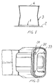
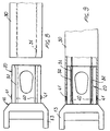
- the arms 3 are made of tubular section members 30, of a substantially oval configuration, and which are provided, in their inside, with a plurality of tooth element 31 engaging in grooves 32, formed on a respective face of the end-pieces 20 and inside the hollow 33 provided on the other faces of the end-pieces 20.
- the groove 32 and sidewalls of the hollow 33 are made with the engagement walls with the tooth elements, providing a changing of the slanting of the laying plane, thereby, as the section member 30 and end-piece 20 are pressure coupled, the fins are bent to provide a deforming effect.
- Said fins are partially turned thereby to firmly clamp the section member 30 on the end-piece 20, to provide a firm coupling without the need of using screws or rivets.
- the tooth element 40 have a rectangular trapezium configuration, with the raising ramp facing the free end of the end-piece 20.
- said tooth elements 40 and 41 provides a further safety element, since said tooth elements would prevent the fins or tooth elements 31 deformed by slanting the wall of the groove 32, from disengaging and causing a labile connection.
- the tooth elements 40 and 41 will provide a deformation localized on the section member 30 thereby enhancing the locking of the section member and end-piece.
- Such a deformation is carried out by gradually turning the contacting surfaces.
Landscapes
- Engineering & Computer Science (AREA)
- Architecture (AREA)
- Civil Engineering (AREA)
- Structural Engineering (AREA)
- Curtains And Furnishings For Windows Or Doors (AREA)
- Building Awnings And Sunshades (AREA)
- Blinds (AREA)
Applications Claiming Priority (2)
| Application Number | Priority Date | Filing Date | Title |
|---|---|---|---|
| ITMI991379 | 1999-06-21 | ||
| IT1999MI001379A ITMI991379A1 (it) | 1999-06-21 | 1999-06-21 | Intelaiatura di supporto particolarmente studiata per tende da sole esimili |
Publications (3)
| Publication Number | Publication Date |
|---|---|
| EP1063367A2 true EP1063367A2 (fr) | 2000-12-27 |
| EP1063367A3 EP1063367A3 (fr) | 2002-12-04 |
| EP1063367B1 EP1063367B1 (fr) | 2008-03-05 |
Family
ID=11383202
Family Applications (1)
| Application Number | Title | Priority Date | Filing Date |
|---|---|---|---|
| EP00112777A Expired - Lifetime EP1063367B1 (fr) | 1999-06-21 | 2000-06-16 | Cadre de support pour rideaux de soleil |
Country Status (4)
| Country | Link |
|---|---|
| EP (1) | EP1063367B1 (fr) |
| DE (1) | DE60038208T2 (fr) |
| ES (1) | ES2302673T3 (fr) |
| IT (1) | ITMI991379A1 (fr) |
Cited By (3)
| Publication number | Priority date | Publication date | Assignee | Title |
|---|---|---|---|---|
| WO2005017279A1 (fr) * | 2003-08-01 | 2005-02-24 | Llaza, Sa | Element de bras pour store et bras articule pour store |
| WO2006021333A1 (fr) * | 2004-08-24 | 2006-03-02 | Paul Voss Gmbh & Co. Kg | Bras d'articulation pour store en toile a rouleau, et son procede de fabrication |
| ES2303408A1 (es) * | 2005-07-29 | 2008-08-01 | Block Sun, S.L. | Brazo articulado para toldo extensible con sistema de tension oculto. |
Family Cites Families (2)
| Publication number | Priority date | Publication date | Assignee | Title |
|---|---|---|---|---|
| FR2687186A1 (fr) * | 1992-02-12 | 1993-08-13 | Llaza Sa | Ensemble articule support de toile de store. |
| IT231967Y1 (it) * | 1993-05-25 | 1999-08-10 | Bat Engineering Srl | Tenda da sole a bracci estensibili |
-
1999
- 1999-06-21 IT IT1999MI001379A patent/ITMI991379A1/it unknown
-
2000
- 2000-06-16 ES ES00112777T patent/ES2302673T3/es not_active Expired - Lifetime
- 2000-06-16 DE DE60038208T patent/DE60038208T2/de not_active Expired - Fee Related
- 2000-06-16 EP EP00112777A patent/EP1063367B1/fr not_active Expired - Lifetime
Cited By (5)
| Publication number | Priority date | Publication date | Assignee | Title |
|---|---|---|---|---|
| WO2005017279A1 (fr) * | 2003-08-01 | 2005-02-24 | Llaza, Sa | Element de bras pour store et bras articule pour store |
| WO2006021333A1 (fr) * | 2004-08-24 | 2006-03-02 | Paul Voss Gmbh & Co. Kg | Bras d'articulation pour store en toile a rouleau, et son procede de fabrication |
| US7645088B2 (en) | 2004-08-24 | 2010-01-12 | Paul Voss Gmbh & Co. Kg | Articulated arm for an awning and method for the production thereof |
| AU2005276726B2 (en) * | 2004-08-24 | 2010-01-14 | Paul Voss Gmbh & Co. Kg | Articulated arm for an awning and method for the production thereof |
| ES2303408A1 (es) * | 2005-07-29 | 2008-08-01 | Block Sun, S.L. | Brazo articulado para toldo extensible con sistema de tension oculto. |
Also Published As
| Publication number | Publication date |
|---|---|
| EP1063367B1 (fr) | 2008-03-05 |
| ITMI991379A0 (it) | 1999-06-21 |
| DE60038208D1 (de) | 2008-04-17 |
| EP1063367A3 (fr) | 2002-12-04 |
| DE60038208T2 (de) | 2009-04-02 |
| ITMI991379A1 (it) | 2000-12-21 |
| ES2302673T3 (es) | 2008-08-01 |
Similar Documents
| Publication | Publication Date | Title |
|---|---|---|
| US8267234B2 (en) | Adjustable drive coupling for adjacent architectural coverings | |
| US12480360B2 (en) | Rolling shutter slat | |
| US20140305476A1 (en) | Umbrella rib connector | |
| GB1586247A (en) | Structural arrangement for tensioning a thin planar film | |
| JP5909283B2 (ja) | クロスランナコネクタ、および吊り天井格子 | |
| TW201936099A (zh) | 用於與建築結構遮蓋物一起使用之底軌 | |
| CA2432946C (fr) | Barre utilitaire avec tige courbee | |
| JP2579587B2 (ja) | 改良型ジャッキ用開放端構造 | |
| EP1063367B1 (fr) | Cadre de support pour rideaux de soleil | |
| US5139073A (en) | Tape drum for a venetian blind tilt assembly | |
| US5142747A (en) | Structure of coupling head portion for coiled slide fastener element | |
| FR2644489A1 (fr) | Caniveau dont les bords longitudinaux presentent des profiles de protection des aretes | |
| JP5815252B2 (ja) | スライドファスナ用の下止具 | |
| KR20210020061A (ko) | 차양(awning) 장치 | |
| US2666442A (en) | Flexible umbrella rib | |
| JP2887750B2 (ja) | 回動フック | |
| FR2825734A1 (fr) | Dispositif d'assemblage de panneaux, lattes ou lambris, a repartition de forces | |
| JP3031359U (ja) | シート受け部材 | |
| JP3596141B2 (ja) | シャッターにおけるスラットカーテンの抜止構造 | |
| CN213015015U (zh) | 金属琉璃瓦型屋顶的卷棚瓦组合结构 | |
| JPH018726Y2 (fr) | ||
| CN212201836U (zh) | 卷帘片 | |
| JPS5818553Y2 (ja) | 折り畳み戸 | |
| WO2004009933A1 (fr) | Dispositif de couverture et barre de maintien associee | |
| KR970003946Y1 (ko) | 절첩식 사다리용 조립 스포크(組立 spoke) |
Legal Events
| Date | Code | Title | Description |
|---|---|---|---|
| PUAI | Public reference made under article 153(3) epc to a published international application that has entered the european phase |
Free format text: ORIGINAL CODE: 0009012 |
|
| AK | Designated contracting states |
Kind code of ref document: A2 Designated state(s): AT BE CH CY DE DK ES FI FR GB GR IE IT LI LU MC NL PT SE |
|
| AX | Request for extension of the european patent |
Free format text: AL;LT;LV;MK;RO;SI |
|
| PUAL | Search report despatched |
Free format text: ORIGINAL CODE: 0009013 |
|
| AK | Designated contracting states |
Kind code of ref document: A3 Designated state(s): AT BE CH CY DE DK ES FI FR GB GR IE IT LI LU MC NL PT SE |
|
| AX | Request for extension of the european patent |
Free format text: AL;LT;LV;MK;RO;SI |
|
| 17P | Request for examination filed |
Effective date: 20030319 |
|
| AKX | Designation fees paid |
Designated state(s): DE ES FR GB |
|
| 17Q | First examination report despatched |
Effective date: 20050303 |
|
| 17Q | First examination report despatched |
Effective date: 20050303 |
|
| 17Q | First examination report despatched |
Effective date: 20050303 |
|
| GRAP | Despatch of communication of intention to grant a patent |
Free format text: ORIGINAL CODE: EPIDOSNIGR1 |
|
| GRAS | Grant fee paid |
Free format text: ORIGINAL CODE: EPIDOSNIGR3 |
|
| GRAA | (expected) grant |
Free format text: ORIGINAL CODE: 0009210 |
|
| AK | Designated contracting states |
Kind code of ref document: B1 Designated state(s): DE ES FR GB |
|
| REG | Reference to a national code |
Ref country code: GB Ref legal event code: FG4D |
|
| REF | Corresponds to: |
Ref document number: 60038208 Country of ref document: DE Date of ref document: 20080417 Kind code of ref document: P |
|
| PGFP | Annual fee paid to national office [announced via postgrant information from national office to epo] |
Ref country code: ES Payment date: 20080623 Year of fee payment: 9 |
|
| REG | Reference to a national code |
Ref country code: ES Ref legal event code: FG2A Ref document number: 2302673 Country of ref document: ES Kind code of ref document: T3 |
|
| PGFP | Annual fee paid to national office [announced via postgrant information from national office to epo] |
Ref country code: DE Payment date: 20080617 Year of fee payment: 9 |
|
| PGFP | Annual fee paid to national office [announced via postgrant information from national office to epo] |
Ref country code: FR Payment date: 20080627 Year of fee payment: 9 |
|
| ET | Fr: translation filed | ||
| PGFP | Annual fee paid to national office [announced via postgrant information from national office to epo] |
Ref country code: GB Payment date: 20080620 Year of fee payment: 9 |
|
| PLBE | No opposition filed within time limit |
Free format text: ORIGINAL CODE: 0009261 |
|
| STAA | Information on the status of an ep patent application or granted ep patent |
Free format text: STATUS: NO OPPOSITION FILED WITHIN TIME LIMIT |
|
| 26N | No opposition filed |
Effective date: 20081208 |
|
| GBPC | Gb: european patent ceased through non-payment of renewal fee |
Effective date: 20090616 |
|
| REG | Reference to a national code |
Ref country code: FR Ref legal event code: ST Effective date: 20100226 |
|
| PG25 | Lapsed in a contracting state [announced via postgrant information from national office to epo] |
Ref country code: FR Free format text: LAPSE BECAUSE OF NON-PAYMENT OF DUE FEES Effective date: 20090630 |
|
| PG25 | Lapsed in a contracting state [announced via postgrant information from national office to epo] |
Ref country code: GB Free format text: LAPSE BECAUSE OF NON-PAYMENT OF DUE FEES Effective date: 20090616 |
|
| PG25 | Lapsed in a contracting state [announced via postgrant information from national office to epo] |
Ref country code: DE Free format text: LAPSE BECAUSE OF NON-PAYMENT OF DUE FEES Effective date: 20100101 |
|
| REG | Reference to a national code |
Ref country code: ES Ref legal event code: FD2A Effective date: 20090617 |
|
| PG25 | Lapsed in a contracting state [announced via postgrant information from national office to epo] |
Ref country code: ES Free format text: LAPSE BECAUSE OF NON-PAYMENT OF DUE FEES Effective date: 20090617 |