EP1063383A2 - Machine d'assemblage de vitrages isolants remplis de gaz lourd - Google Patents
Machine d'assemblage de vitrages isolants remplis de gaz lourd Download PDFInfo
- Publication number
- EP1063383A2 EP1063383A2 EP00890072A EP00890072A EP1063383A2 EP 1063383 A2 EP1063383 A2 EP 1063383A2 EP 00890072 A EP00890072 A EP 00890072A EP 00890072 A EP00890072 A EP 00890072A EP 1063383 A2 EP1063383 A2 EP 1063383A2
- Authority
- EP
- European Patent Office
- Prior art keywords
- conveyor
- glass panes
- heavy gas
- glass
- plates
- Prior art date
- Legal status (The legal status is an assumption and is not a legal conclusion. Google has not performed a legal analysis and makes no representation as to the accuracy of the status listed.)
- Withdrawn
Links
- 239000011521 glass Substances 0.000 claims abstract description 80
- 238000007789 sealing Methods 0.000 claims abstract description 18
- 125000006850 spacer group Chemical group 0.000 claims description 25
- 239000007789 gas Substances 0.000 abstract 1
- 239000011261 inert gas Substances 0.000 abstract 1
- 238000005429 filling process Methods 0.000 description 4
- 230000000694 effects Effects 0.000 description 2
- 238000003825 pressing Methods 0.000 description 2
- 229910018503 SF6 Inorganic materials 0.000 description 1
- 238000006073 displacement reaction Methods 0.000 description 1
- 238000009413 insulation Methods 0.000 description 1
- 238000004519 manufacturing process Methods 0.000 description 1
- 239000000203 mixture Substances 0.000 description 1
- 230000000630 rising effect Effects 0.000 description 1
- 238000004904 shortening Methods 0.000 description 1
- SFZCNBIFKDRMGX-UHFFFAOYSA-N sulfur hexafluoride Chemical compound FS(F)(F)(F)(F)F SFZCNBIFKDRMGX-UHFFFAOYSA-N 0.000 description 1
- 229960000909 sulfur hexafluoride Drugs 0.000 description 1
- 230000001360 synchronised effect Effects 0.000 description 1
Images


Classifications
-
- E—FIXED CONSTRUCTIONS
- E06—DOORS, WINDOWS, SHUTTERS, OR ROLLER BLINDS IN GENERAL; LADDERS
- E06B—FIXED OR MOVABLE CLOSURES FOR OPENINGS IN BUILDINGS, VEHICLES, FENCES OR LIKE ENCLOSURES IN GENERAL, e.g. DOORS, WINDOWS, BLINDS, GATES
- E06B3/00—Window sashes, door leaves, or like elements for closing wall or like openings; Layout of fixed or moving closures, e.g. windows in wall or like openings; Features of rigidly-mounted outer frames relating to the mounting of wing frames
- E06B3/66—Units comprising two or more parallel glass or like panes permanently secured together
- E06B3/677—Evacuating or filling the gap between the panes ; Equilibration of inside and outside pressure; Preventing condensation in the gap between the panes; Cleaning the gap between the panes
- E06B3/6775—Evacuating or filling the gap during assembly
Definitions
- the invention relates to a device for assembling insulating glass panes, whose interior is filled with a heavy gas, having the features of the introductory part of claim 1.
- the invention has for its object a device Specify the type mentioned above, which does not have these disadvantages having.
- the device according to the invention is between the lower horizontal Edge of the two panes of glass and the conveyor belt on which the glass panes stand up, deliberately given a leak, so that the glass panes on the conveyor belt are not gas-tight, so that the space between the gas disks of the disk package is not only for Side and possibly upwards, but also downwards is open.
- the device according to the invention has in the preferred embodiment two essentially perpendicular, preferably opposite the vertical slightly, e.g. by 3 to 5 °, backwards inclined, parallel plates 1 and 2.
- the plates 1 and 2 can be the plates of a device for pressing of insulating glass panes.
- the plate 1 is attached to the frame of the device.
- the Plate 2 is over pressure medium cylinder (not shown) and in the direction the double arrow 3 (Fig. 2 and 3) displaceable.
- a belt conveyor 5 with two to each other parallel conveyor belts 17 are provided on the rising and against the frame-fixed, for example designed as an air cushion wall Plate 1 leaning against a package 10 consisting of two glass panes 11 and 12 and a spacer 13 in the space 4 between the plates 1 and 2 can be funded.
- the plates 1 and 2 can seal against the belt conveyor 5 his. Exemplary embodiments for this are shown in FIGS. 2 and 3.
- the sealing strip 15 is, for example, of at least two pressure medium cylinders 6 and is the lower edge of the Plate 2 and the guide bar 16 on which the upper run 17 of the Belt conveyor 5 slides, assigned.
- the sealing strip 15 is in the In the embodiment shown in Fig. 2 formed as a hose seal and consists for example of elastically deformable plastic. To increase the sealing effect, the sealing strip 15 can be used as soon as them in their active position, in which they are adjustable at the bottom Plate 2 and against the guide bar 16, pressurized become.
- the guide bar 16 of the belt conveyor 5 is on the sealing bar 15 opposite side continuously, for example over a strip 18 connected to the fixed plate 1 so that a gas-tight seal is also guaranteed there.
- Fig. 3 is at the bottom adjustable plate 2 continuously an elastically deformable sealing tab 20 provided, which when moving the movable Plate 2 on the edge arranged below the movable plate 2 the guide bar 16 of the belt conveyor 5 creates.
- the sealing tab 20 shown in FIG. 3 can also be used as an inflatable Hose seal to be formed.
- a movable hose attached to the movable press plate 2 as a seal is that is pressurized so that the seal from the side and / or from above to that of the movable press plate 2 adjacent edge of the guide bar 16 of the belt conveyor 5 creates as soon as the movable plate 2 is arranged in the position is in which heavy gas is introduced.
- fixed plate 1 To act on the air cushion wall, for example fixed plate 1 is this with a connection for feeding equipped with compressed air (not shown).
- a second sealing device 26 is in the direction of the device of the double arrow 27 in Fig. 1.
- the sealing device can do this 26 on guide rails fastened in the machine frame guided over slide and by a drive, not shown be movable.
- a channel 30 is provided, from the heavy gas as symbolized by arrows 31 by the belt conveyor 5 in Example between conveyor belts 17 from below into room 4 flows in.
- the effective length of the channel 30 is adjustable Piston 32 limited to the length of the disc package 10.
- channel 30 shown for supplying heavy gas.
- the channel 30 below the carrier 33 for the guide bar 16 of the longitudinally divided belt conveyor 5 (in the example a belt conveyor with two endless toothed belts attached as conveyor belts 17).
- From the interior 35 of the channel 30 go from holes 36 which with holes 37 in Align carrier 33 and eventually lead to pipe pieces 38 which the Gap between the two conveyor belts 17 of the belt conveyor 5 push through.
- the pipe sections 38 open in space 4 between the plates 1 and 2, in particular between the two glass panes 11 and 12 of the Disk pack 10 and are aligned so that they are the spacer 13 are opposite, that is, opposite the gap 48 between spacers 13 and glass pane 12 are laterally offset.
- a series of long slots or a continuous slot may be provided.
- the interior 35 of the channel 30 stands over a connecting line (not shown) with a source of heavy gas (rare gas, sulfur hexafluoride or the like.) in connection.
- a source of heavy gas ultraviolet gas, sulfur hexafluoride or the like.
- piston 32 be displaced with the displacement the movable seal 26 is synchronized.
- the device works, for example, as follows:
- the device according to the invention can also be used that the glass sheet 12 during the filling process from the plate 2 sucked in and completely at a distance from the glass pane 11 attached spacer 13 is held. This is straightforward possible if the plate 2, for example, by using negative pressure acted openings set up for holding the glass sheet 12 is.
- the first glass pane 12 is in the space 4 between the plates 1 and 2 moved to a predetermined end position.
- the adjustable plate 2 is advanced until it touches the glass pane 12 is present. Then the openings of the plate 2 with Vacuum applied so that the glass plate 12 with the plate 2nd can be moved away from the plate 1.
- the second glass plate 11 is also on it attached spacer 13 to the predetermined end position in Room 4 transported.
- the sealing devices 25, 26 in addition to the package 10 from the glass panes 11, 12 and the spacer 13 is arranged.
- the heavy gas supply interrupted.
- the glass pane 12 is placed on the spacer frame 13, by advancing the plate 2 so that the insulating glass pane closed is. Subsequently, the gas-filled insulating glass pane be pressed.
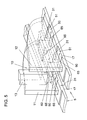
- the outside or top is the conveyor belts 17 of the belt conveyor 5 are provided with depressions 50, so that the lower edge of the glass panes 11 and 12 on the Conveyor belts 17 do not stand up over the entire length, but instead between the lower edge of the glass panes 11 and 12 and the conveyor belts 17 gas passage openings 51 are formed.
- the recesses 50 with flat-rectangular cross-sectional shape and have, for example a length of 20 to 30 mm and a depth of 2 to 3 mm.
- the glass panes 11 and 12 of the Disk package 10 after the filling process of the room 4 by the Press plates 1 and 2 and is limited by the seals 25 and 26 and in which the disk package 10 is moved towards each other until the Glass pane 12 is connected to the spacer 13.
- This Closing the disk package 10 occurs when there are no special ones Measures are taken, overpressure in the insulating glass pane, because heavy gas is not moving quickly enough from the space between the glass panes 11 and 12 can escape. In particular, it should be borne in mind that this is a heavy gas that is not easy and quickly displaced from the space between the glass panes 11 and 12 can be. Such overpressure has the consequence that the glass panes 11 and 12 in the finished insulating glass pane to the outside are arched, which is undesirable.
- the glass panes 11 and 12 of the Disc pack 10 at its lower edges opposite the conveyor 5 not to seal, but the area of the conveyor 5, on which the glass panes 11 and 12 stand up, consciously gas permeable, can be when closing the insulating glass pane Heavy gas not only over the two side edges of the disc package 10, that is in the area of the seals 25 and 26, and if necessary also upwards (if the glass pane 12 is filling up with gas completely at a distance from the spacer 13) escape (Arrows 45 in Fig.1), but also across the bottom through the Passages 51 between the lower edges of the glass panes 11 and 12 and the conveyor belts 17 (arrows 65 in Fig. 5).
- Heavy gas losses can be limited by the cross-sectional area of the passage openings 50 between the lower edges of the Glass panes 11 and 12 is kept small. Prevent additionally the optionally provided, shown in Figs. 2 and 3 Seals 15, 18, 20 significant losses of heavy gas.
- an embodiment of the invention can be as follows being represented:
- a device for producing heavy gas filled Insulating glass panes are the glass panes 11, 12 of a pane package from two glass panes 11, 12 and a spacer 13 after not sealed at the bottom. This results from the fact that the Conveyor belts 17 on which the disk package 10 stands, on their Wells 50 spaced apart on the outside have, so that between the lower edges of the glass panes 11, 12 of the disk package 10 and the conveyor belts 17 of the belt conveyor 5 through openings 51 are provided.
- These through holes 51 allow that in the area of the lower edge of the disc package 10 rooms 60 completely flushed with heavy gas be, on the one hand, and that on the other hand when closing the disc pact 10 by placing the glass pane 12 on the spacer 13 pressure equalization also across the lower edge, namely through the through openings 51 can be done so that faster than before can be put together and pressed without being in the insulating glass pane Overpressure arises.
Landscapes
- Engineering & Computer Science (AREA)
- Civil Engineering (AREA)
- Structural Engineering (AREA)
- Securing Of Glass Panes Or The Like (AREA)
- Joining Of Glass To Other Materials (AREA)
Applications Claiming Priority (2)
| Application Number | Priority Date | Filing Date | Title |
|---|---|---|---|
| AT109999A AT407552B (de) | 1999-06-22 | 1999-06-22 | Vorrichtung zum zusammenbauen von isolierglasscheiben, deren innenraum mit einem schwergas gefüllt ist |
| AT109999 | 1999-06-22 |
Publications (2)
| Publication Number | Publication Date |
|---|---|
| EP1063383A2 true EP1063383A2 (fr) | 2000-12-27 |
| EP1063383A3 EP1063383A3 (fr) | 2002-09-25 |
Family
ID=3506578
Family Applications (1)
| Application Number | Title | Priority Date | Filing Date |
|---|---|---|---|
| EP00890072A Withdrawn EP1063383A3 (fr) | 1999-06-22 | 2000-03-14 | Machine d'assemblage de vitrages isolants remplis de gaz lourd |
Country Status (2)
| Country | Link |
|---|---|
| EP (1) | EP1063383A3 (fr) |
| AT (1) | AT407552B (fr) |
Cited By (5)
| Publication number | Priority date | Publication date | Assignee | Title |
|---|---|---|---|---|
| DE102004032435A1 (de) * | 2004-07-05 | 2006-02-02 | Lenhardt Maschinenbau Gmbh | Verfahren und Vorrichtung zum Zusammenbauen von Isolierglasscheiben, die mit einem von Luft verschiedenen Gas gefüllt sind. |
| DE102010035748A1 (de) | 2010-04-29 | 2011-11-03 | Bystronic Lenhardt Gmbh | Verfahren zum Zusammenbauen von Isolierglasscheiben, die drei zueinander parallele Glasplatten haben |
| US8905085B2 (en) | 2011-09-09 | 2014-12-09 | Erdman Automation Corporation | Apparatus for edge sealing and simultaneous gas filling of insulated glass units |
| US10113354B2 (en) | 2013-12-31 | 2018-10-30 | Cardinal Ig Company | Multiple-pane insulating glazing unit assembly, gas filling, and pressing machine |
| FR3067741A1 (fr) * | 2017-06-19 | 2018-12-21 | Saint-Gobain Glass France | Procede et installation de fabrication de vitrage isolant |
Citations (1)
| Publication number | Priority date | Publication date | Assignee | Title |
|---|---|---|---|---|
| EP0674086A1 (fr) | 1994-03-24 | 1995-09-27 | Peter Lisec | Procédé d'assemblage de vitrages isolants remplis de gaz lourd ainsi qu'un dispositif de remplissage afférent |
Family Cites Families (3)
| Publication number | Priority date | Publication date | Assignee | Title |
|---|---|---|---|---|
| DE3101342C2 (de) * | 1981-01-17 | 1984-08-02 | Vereinigte Glaswerke Gmbh, 5100 Aachen | "Verfahren zur Herstellung von gasgefüllten Isolierglaseinheiten und Vorrichtung zur Durchführung des Verfahrens" |
| DE4307403A1 (de) * | 1993-03-09 | 1994-09-15 | Cta Composite Tech Autom Gmbh | Verfahren und Vorrichtung zum Einrichten, Gasfüllen und Verpressen von Einzelscheiben und/oder bereits vorgefertigten Scheibenanordnungen als zwei Komponenten bei der Herstellung von Isolierglasscheiben |
| DE4419052A1 (de) * | 1994-05-31 | 1995-12-07 | Dcl Glas Consult Gmbh | Verfahren und Vorrichtung zum Befüllen eines Zwischenraumes einer Isolierglaseinheit |
-
1999
- 1999-06-22 AT AT109999A patent/AT407552B/de not_active IP Right Cessation
-
2000
- 2000-03-14 EP EP00890072A patent/EP1063383A3/fr not_active Withdrawn
Patent Citations (1)
| Publication number | Priority date | Publication date | Assignee | Title |
|---|---|---|---|---|
| EP0674086A1 (fr) | 1994-03-24 | 1995-09-27 | Peter Lisec | Procédé d'assemblage de vitrages isolants remplis de gaz lourd ainsi qu'un dispositif de remplissage afférent |
Cited By (13)
| Publication number | Priority date | Publication date | Assignee | Title |
|---|---|---|---|---|
| DE102004032435A1 (de) * | 2004-07-05 | 2006-02-02 | Lenhardt Maschinenbau Gmbh | Verfahren und Vorrichtung zum Zusammenbauen von Isolierglasscheiben, die mit einem von Luft verschiedenen Gas gefüllt sind. |
| DE102004032435B4 (de) * | 2004-07-05 | 2006-12-21 | Lenhardt Maschinenbau Gmbh | Verfahren und Vorrichtung zum Zusammenbauen von Isolierglasscheiben, die mit einem von Luft verschiedenen Gas gefüllt sind. |
| US8632648B2 (en) | 2004-07-05 | 2014-01-21 | Peter Schuler | Method and device for the assembly of insulating glass panes that are filled with a gas different from air |
| WO2011134565A1 (fr) | 2010-04-29 | 2011-11-03 | Bystronic Lenhardt Gmbh | Procédé d'assemblage de vitrages isolants comportant trois plaques de verre parallèles les unes aux autres |
| DE102010035748B4 (de) * | 2010-04-29 | 2013-01-03 | Bystronic Lenhardt Gmbh | Verfahren zum Zusammenbauen von Isolierglasscheiben, die drei zueinander parallele Glasplatten haben |
| CN102959172A (zh) * | 2010-04-29 | 2013-03-06 | 百超伦哈特有限公司 | 装配具有三个互相平行玻璃板的中空玻璃窗格的方法 |
| DE102010035748A1 (de) | 2010-04-29 | 2011-11-03 | Bystronic Lenhardt Gmbh | Verfahren zum Zusammenbauen von Isolierglasscheiben, die drei zueinander parallele Glasplatten haben |
| CN102959172B (zh) * | 2010-04-29 | 2014-12-24 | 百超伦哈特有限公司 | 装配具有三个互相平行玻璃板的中空玻璃窗格的方法 |
| US8905085B2 (en) | 2011-09-09 | 2014-12-09 | Erdman Automation Corporation | Apparatus for edge sealing and simultaneous gas filling of insulated glass units |
| US10113354B2 (en) | 2013-12-31 | 2018-10-30 | Cardinal Ig Company | Multiple-pane insulating glazing unit assembly, gas filling, and pressing machine |
| US11168515B2 (en) | 2013-12-31 | 2021-11-09 | Cardinal Ig Company | Multiple-pane insulating glazing unit assembly, gas filling, and pressing machine |
| FR3067741A1 (fr) * | 2017-06-19 | 2018-12-21 | Saint-Gobain Glass France | Procede et installation de fabrication de vitrage isolant |
| WO2018234035A1 (fr) * | 2017-06-19 | 2018-12-27 | Saint-Gobain Glass France | Procédé et installation de fabrication de vitrage isolant |
Also Published As
| Publication number | Publication date |
|---|---|
| AT407552B (de) | 2001-04-25 |
| ATA109999A (de) | 2000-08-15 |
| EP1063383A3 (fr) | 2002-09-25 |
Similar Documents
| Publication | Publication Date | Title |
|---|---|---|
| EP0674086B1 (fr) | Procédé d'assemblage de vitrages isolants remplis de gaz lourd ainsi qu'un dispositif de remplissage afférent | |
| DE3101342C2 (de) | "Verfahren zur Herstellung von gasgefüllten Isolierglaseinheiten und Vorrichtung zur Durchführung des Verfahrens" | |
| EP0603148B1 (fr) | Procédé et dispositif pour remplir des vitrages isolants avec un gaz différent de l'air | |
| EP1730378B1 (fr) | Procede de positionnement de plaques de verre dans un dispositif vertical d'assemblage et de compression de vitres en verre isolant | |
| AT396782B (de) | Vorrichtung zum fördern von gegenüber der lotrechten etwas geneigten isolierglasscheiben | |
| EP1157184A1 (fr) | Dispositif permettant de transporter des vitres isolantes | |
| EP1450001B1 (fr) | Dispositif d'assemblage de vitrages isolants, remplis de gaz lourd | |
| DE4437998C2 (de) | Vorrichtung zum Zusammenbauen von Isolierglasscheiben | |
| DE102015118960A1 (de) | Verfahren und Vorrichtung zum Zusammenbauen von Glastafeln zu Isolierglasscheiben | |
| DE102004009860B4 (de) | Verfahren und Vorrichtung zum Zusammenbauen von Isolierglasscheiben, die mit einem von Luft verschiedenen Gas gefüllt sind | |
| DE102005044861B3 (de) | Verfahren und Vorrichtung zum Füllen von Isolierglasscheiben mit einem von Luft verschiedenen Gas | |
| EP3133234A1 (fr) | Procede et dispositif d'assemblage de panneaux en verre et de vitres isolantes | |
| AT407552B (de) | Vorrichtung zum zusammenbauen von isolierglasscheiben, deren innenraum mit einem schwergas gefüllt ist | |
| EP0857849B1 (fr) | Procédé et dispositif d'assemblage et pour vitrifier de vitrages isolants | |
| DE10138346C2 (de) | Vorrichtung zum Zusammenbauen von Isolierglasscheiben | |
| EP0857848B1 (fr) | Procédé et dispositif d'assemblage de vitrages isolants | |
| AT409128B (de) | Verfahren zum zusammenbauen von isolierglasscheiben, deren innenraum mit einem schwergas gefüllt ist | |
| AT409263B (de) | Vorrichtung zum füllen von isolierglasscheiben mit füllgas | |
| DE7728259U1 (de) | Maschine zum bearbeiten der bretter von tuerrahmen |
Legal Events
| Date | Code | Title | Description |
|---|---|---|---|
| PUAI | Public reference made under article 153(3) epc to a published international application that has entered the european phase |
Free format text: ORIGINAL CODE: 0009012 |
|
| AK | Designated contracting states |
Kind code of ref document: A2 Designated state(s): AT BE CH CY DE DK ES FI FR GB GR IE IT LI LU MC NL PT SE |
|
| AX | Request for extension of the european patent |
Free format text: AL;LT;LV;MK;RO;SI |
|
| PUAL | Search report despatched |
Free format text: ORIGINAL CODE: 0009013 |
|
| AK | Designated contracting states |
Kind code of ref document: A3 Designated state(s): AT BE CH CY DE DK ES FI FR GB GR IE IT LI LU MC NL PT SE |
|
| AX | Request for extension of the european patent |
Free format text: AL;LT;LV;MK;RO;SI |
|
| AKX | Designation fees paid | ||
| REG | Reference to a national code |
Ref country code: DE Ref legal event code: 8566 |
|
| STAA | Information on the status of an ep patent application or granted ep patent |
Free format text: STATUS: THE APPLICATION IS DEEMED TO BE WITHDRAWN |
|
| 18D | Application deemed to be withdrawn |
Effective date: 20030326 |