EP1063390A2 - Turbolader - Google Patents
Turbolader Download PDFInfo
- Publication number
- EP1063390A2 EP1063390A2 EP00112173A EP00112173A EP1063390A2 EP 1063390 A2 EP1063390 A2 EP 1063390A2 EP 00112173 A EP00112173 A EP 00112173A EP 00112173 A EP00112173 A EP 00112173A EP 1063390 A2 EP1063390 A2 EP 1063390A2
- Authority
- EP
- European Patent Office
- Prior art keywords
- turbocharger
- turbine wheel
- compressor
- shaft
- sealing air
- Prior art date
- Legal status (The legal status is an assumption and is not a legal conclusion. Google has not performed a legal analysis and makes no representation as to the accuracy of the status listed.)
- Withdrawn
Links
- 238000007789 sealing Methods 0.000 claims description 28
- 230000000903 blocking effect Effects 0.000 abstract 3
- 239000007789 gas Substances 0.000 description 9
- 238000009795 derivation Methods 0.000 description 7
- 239000000203 mixture Substances 0.000 description 3
- 239000002360 explosive Substances 0.000 description 2
- 238000004939 coking Methods 0.000 description 1
- 230000006835 compression Effects 0.000 description 1
- 238000007906 compression Methods 0.000 description 1
- 238000010276 construction Methods 0.000 description 1
- 230000007613 environmental effect Effects 0.000 description 1
- 238000004880 explosion Methods 0.000 description 1
- 239000010687 lubricating oil Substances 0.000 description 1
- 239000003921 oil Substances 0.000 description 1
Images
Classifications
-
- F—MECHANICAL ENGINEERING; LIGHTING; HEATING; WEAPONS; BLASTING
- F02—COMBUSTION ENGINES; HOT-GAS OR COMBUSTION-PRODUCT ENGINE PLANTS
- F02B—INTERNAL-COMBUSTION PISTON ENGINES; COMBUSTION ENGINES IN GENERAL
- F02B37/00—Engines characterised by provision of pumps driven at least for part of the time by exhaust
-
- F—MECHANICAL ENGINEERING; LIGHTING; HEATING; WEAPONS; BLASTING
- F01—MACHINES OR ENGINES IN GENERAL; ENGINE PLANTS IN GENERAL; STEAM ENGINES
- F01D—NON-POSITIVE DISPLACEMENT MACHINES OR ENGINES, e.g. STEAM TURBINES
- F01D11/00—Preventing or minimising internal leakage of working-fluid, e.g. between stages
- F01D11/02—Preventing or minimising internal leakage of working-fluid, e.g. between stages by non-contact sealings, e.g. of labyrinth type
- F01D11/04—Preventing or minimising internal leakage of working-fluid, e.g. between stages by non-contact sealings, e.g. of labyrinth type using sealing fluid, e.g. steam
-
- F—MECHANICAL ENGINEERING; LIGHTING; HEATING; WEAPONS; BLASTING
- F02—COMBUSTION ENGINES; HOT-GAS OR COMBUSTION-PRODUCT ENGINE PLANTS
- F02B—INTERNAL-COMBUSTION PISTON ENGINES; COMBUSTION ENGINES IN GENERAL
- F02B37/00—Engines characterised by provision of pumps driven at least for part of the time by exhaust
- F02B37/005—Exhaust driven pumps being combined with an exhaust driven auxiliary apparatus, e.g. a ventilator
-
- F—MECHANICAL ENGINEERING; LIGHTING; HEATING; WEAPONS; BLASTING
- F02—COMBUSTION ENGINES; HOT-GAS OR COMBUSTION-PRODUCT ENGINE PLANTS
- F02B—INTERNAL-COMBUSTION PISTON ENGINES; COMBUSTION ENGINES IN GENERAL
- F02B37/00—Engines characterised by provision of pumps driven at least for part of the time by exhaust
- F02B37/04—Engines with exhaust drive and other drive of pumps, e.g. with exhaust-driven pump and mechanically-driven second pump
- F02B37/10—Engines with exhaust drive and other drive of pumps, e.g. with exhaust-driven pump and mechanically-driven second pump at least one pump being alternatively or simultaneously driven by exhaust and other drive, e.g. by pressurised fluid from a reservoir or an engine-driven pump
-
- F—MECHANICAL ENGINEERING; LIGHTING; HEATING; WEAPONS; BLASTING
- F05—INDEXING SCHEMES RELATING TO ENGINES OR PUMPS IN VARIOUS SUBCLASSES OF CLASSES F01-F04
- F05D—INDEXING SCHEME FOR ASPECTS RELATING TO NON-POSITIVE-DISPLACEMENT MACHINES OR ENGINES, GAS-TURBINES OR JET-PROPULSION PLANTS
- F05D2220/00—Application
- F05D2220/40—Application in turbochargers
-
- Y—GENERAL TAGGING OF NEW TECHNOLOGICAL DEVELOPMENTS; GENERAL TAGGING OF CROSS-SECTIONAL TECHNOLOGIES SPANNING OVER SEVERAL SECTIONS OF THE IPC; TECHNICAL SUBJECTS COVERED BY FORMER USPC CROSS-REFERENCE ART COLLECTIONS [XRACs] AND DIGESTS
- Y02—TECHNOLOGIES OR APPLICATIONS FOR MITIGATION OR ADAPTATION AGAINST CLIMATE CHANGE
- Y02T—CLIMATE CHANGE MITIGATION TECHNOLOGIES RELATED TO TRANSPORTATION
- Y02T10/00—Road transport of goods or passengers
- Y02T10/10—Internal combustion engine [ICE] based vehicles
- Y02T10/12—Improving ICE efficiencies
Definitions
- the invention is a turbocharger according to the preamble of Claim 1.
- the turbocharger is from one Centrifugal compressor with a bladed or unbladed diffuser and out a radial turbine.
- the rotor of the turbocharger consists of a shaft at one end of which the turbine wheel and at the other end the Compressor wheel is attached.
- the Shaft mounted on slide bearings lubricated with pressure oil.
- the housing can for example, uncooled or water-cooled.
- the path of the sealing air removed from the compressor is in the figure 1 indicated with white arrows.
- the turbine-side bearing is provided by the supply of sealing air no higher temperatures than the compressor-side storage.
- the Temperature level therefore poses no problem even after the engine is switched off so that there is no undesirable coking of the lubricating oil.
- the rooms on both sides of the storage room are not to receive any excess pressure Storage room connected to the atmosphere by channels.
- the bearing housing will by an intermediate wall, which is cooled by the sealing air, effectively against the protected high temperature of the turbine space.
- This type of has a disadvantage Sealing air supply, however, particularly when there is a gas for the compressor air is mixed, which can occur, for example, in the compression of biogas. This can lead to explosive sealing air compositions, which ignite in the hot environment of the turbine hub. A direct withdrawal the sealing air from the compressor is thus impossible. The one with the gas Enriched sealing air should also not be released into the environment. Is problematic this is because external air is often not available in the required amount, and separate Compressors represent a significant price disadvantage. This applies particularly to Turbochargers with variable geometry (VTG), because they require more sealing air to have.
- VVTG variable geometry
- the aim of the invention is to overcome these disadvantages.
- the invention solves the Task to create a turbocharger with which it is possible to Enrich the compressor air with a gas without risk of explosion Sealing air due to an increased temperature of the turbine wheel of the turbocharger to fear. It should also be avoided for environmental reasons, to release the sealing air enriched with the gas mixture to the environment.
- this object is achieved in a turbocharger according to the Preamble of claim 1 solved in that a small turbocharger, which a shaft, a compressor attached to the shaft with a feed line and one Discharge and a turbine wheel attached to the shaft with a feed line and a Derivation contains, is arranged so that the discharge of the compressor of the Small turbocharger for supplying sealing air to the turbine wheel of the turbocharger connected.
- a gas can advantageously be mixed with the air of the turbocharger, since the Sealing air is supplied by the compressor of the small turbocharger.
- a turbocharger with variable Geometry as this is characterized by increased sealing air consumption.
- the sealing air pressure of the Turbocharger to the turbine inlet pressure by itself.
- the feed and discharge lines of the small turbine wheel with the feed and Derivations of the turbine wheel via a general control - on pressure reducing element such as a cover - to connect.
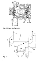
- FIG. 1 An embodiment of a turbocharger 1 according to the invention is shown schematically in FIG.
- the turbocharger 1 consists of a shaft 2, at one end of which there is a compressor V 1 and a turbine wheel T 1 .
- the housing, the bearings and all other things known from the prior art have been omitted for the sake of simplicity.
- the compressor V 1 is connected to a feed line 3 and a discharge line 4, just as a feed line 5 and a discharge line 6 are connected to the turbine wheel T 1 .
- the turbocharger is a turbocharger with variable geometry, since it is characterized by an increased sealing air supply.
- the air of the compressor V 1 is enriched with a gas in the exemplary embodiment shown and, for this reason, cannot be used as a sealing air supply for the turbine wheel T 1 , since explosive gas mixtures can arise which ignite in the vicinity of the hot turbine wheel T 1 .
- a small turbocharger 8 is arranged next to the turbocharger 1, which is also shown only schematically in FIG. 2.
- the basic construction of this small turbocharger 8 consists of a shaft 2a, to which a compressor V 2 and a turbine wheel T 2 are attached. Inlets and outlets 3a, 5a, 4a, 6a are connected to both the compressor V 2 and the turbine wheel T 2 .
- the supply and discharge lines 5a, 6a of the turbine wheel T 2 of the small turbine 8 are each connected to the supply and discharge lines 5, 6 of the turbine wheel T1 of the turbocharger 1.
- an orifice 7 or another pressure-reducing element is arranged between the supply line 5 and supply line 5a in the exemplary embodiment shown.
- the sealing air supply to the turbine wheel T 1 of the turbocharger 1 is operated according to FIG. 2 by the derivation 4a of the compressor V 2 of the small turbocharger 8.
- the sealing air is then released to the environment in a known manner, but this is not shown in FIG. 2.
- This arrangement of a small turbocharger 8 as sealing air supply for a turbine wheel of a turbocharger 1 has various advantages.
- the sealing air can be released to the environment without hesitation, since - in contrast to the compressor air of the compressor V 1 - it contains no gas admixture.
- Another advantage is that the pressure of the sealing air in the circuit shown in FIG. 2 adapts itself to the turbine inlet pressure.
Landscapes
- Engineering & Computer Science (AREA)
- Mechanical Engineering (AREA)
- General Engineering & Computer Science (AREA)
- Chemical & Material Sciences (AREA)
- Combustion & Propulsion (AREA)
- Supercharger (AREA)
- Structures Of Non-Positive Displacement Pumps (AREA)
Abstract
Description
- Fig.1
- einen Turbolader, welcher aus dem Stand der Technik bekannt ist, mit herkömmlicher Sperrluftversorgung des Turbinenrades durch Luft aus dem Verdichter und
- Fig.2
- einen erfindungsgemässen Turbolader mit der Verwendung eines Kleinturboladers für die Sperrluftversorgung des Turboladers.
- 1
- Turbolader
- 2
- Welle von Turbolader 1
- 2a
- Welle von Kleinturbolader 8
- 3
- Zuleitung von Verdichter V1
- 3a
- Zuleitung von Verdichter V2
- 4
- Ableitung von Verdichter V1
- 4a
- Ableitung von Verdichter V2
- 5
- Zuleitung von Turbinenrad T1
- 5a
- Zuleitung von Turbinenrad T2
- 6
- Ableitung von Turbinenrad T1
- 6a
- Ableitung von Turbinenrad T2
- 7
- Blende
- 8
- Kleinturbolader
- T1
- Turbinenrad von Turbolader 1
- T2
- Turbinenrad von Kleinturbolader 8
- V1
- Verdichter von Turbolader 1
- V2
- Verdichter von Kleinturbolader 8
Claims (4)
- Turbolader (1), welcher eine Welle (2), einen an der Welle (2) befestigten Verdichter (V1) mit einer Zuleitung (3) und einer Ableitung (4), sowie ein an der Welle (2) befestigtes Turbinenrad (T1) mit einer Zuleitung (5) und einer Ableitung (6), und eine Sperrluftversorgung des Turbinenrades (T1) enthält,
dadurch gekennzeichnet, dass
die Sperrluftversorgung einen Kleinturbolader (8) mit einer Welle (2a) sowie einen an der Welle (2a) befestigen Verdichter (V2) mit einer Zuleitung (3a) und einer Ableitung (4a) und ein an der Welle (2a) befestigtes Turbinenrad (T2) mit einer Zuleitung (5a) und einer Ableitung (6a) aufweist, wobei die Ableitung (4a) des Verdichters (V2) des Kleinturboladers (8) direkt mit einem Sperrluftzugang des Turbinenrades (T1) des Turboladers (1) verbunden ist. - Turbolader (1) nach Anspruch 1,
dadurch gekennzeichnet, dass
der Turbolader (1) ein Turbolader veränderlicher Geometrie ist. - Turbolader (1) nach Anspruch 1 oder 2,
dadurch gekennzeichnet, dass
die Zuleitung (5a) des Turbinenrades (T2) des Kleinturboladers (8) von der Zuleitung (5) des Turboladers (T1) abzweigt und die Ableitung (6a) des Turbinenrades (T2) des Kleinturboladers (8) in die Ableitung (6) des Turbinenrades (T1) des Turboladers (1) mündet. - Turbolader (1) nach Anspruch 3,
dadurch gekennzeichnet, dass
in der Zuleitung (5a) des Kleinturboladers (T2) ein druckminderndes Element (7) angeordnet ist.
Applications Claiming Priority (2)
| Application Number | Priority Date | Filing Date | Title |
|---|---|---|---|
| DE19928925 | 1999-06-24 | ||
| DE19928925A DE19928925A1 (de) | 1999-06-24 | 1999-06-24 | Turbolader |
Publications (2)
| Publication Number | Publication Date |
|---|---|
| EP1063390A2 true EP1063390A2 (de) | 2000-12-27 |
| EP1063390A3 EP1063390A3 (de) | 2003-08-20 |
Family
ID=7912368
Family Applications (1)
| Application Number | Title | Priority Date | Filing Date |
|---|---|---|---|
| EP00112173A Withdrawn EP1063390A3 (de) | 1999-06-24 | 2000-06-07 | Turbolader |
Country Status (4)
| Country | Link |
|---|---|
| US (1) | US6318086B1 (de) |
| EP (1) | EP1063390A3 (de) |
| JP (1) | JP2001020748A (de) |
| DE (1) | DE19928925A1 (de) |
Cited By (1)
| Publication number | Priority date | Publication date | Assignee | Title |
|---|---|---|---|---|
| EP4124734A1 (de) * | 2021-07-26 | 2023-02-01 | Volvo Truck Corporation | Brennkraftmaschinensystem |
Families Citing this family (6)
| Publication number | Priority date | Publication date | Assignee | Title |
|---|---|---|---|---|
| US6460519B1 (en) * | 2000-10-04 | 2002-10-08 | Caterpillar Inc | Twin turbine exhaust gas re-circulation system having fixed geometry turbines |
| DE602004028875D1 (de) * | 2004-07-09 | 2010-10-07 | Honeywell Int Inc | Turboladergehäuse, turbolader und multiturboladersystem |
| US8387385B2 (en) * | 2004-08-31 | 2013-03-05 | The United States Of America, As Represented By The Administrator Of The U.S. Environmental Protection Agency | Efficient bypass valve for multi-stage turbocharging system |
| JP5449062B2 (ja) * | 2010-07-02 | 2014-03-19 | 三菱重工業株式会社 | 排ガスタービン過給機のシールエア供給装置 |
| US10697388B2 (en) | 2013-01-25 | 2020-06-30 | Transportation Ip Holdings, Llc | Method and system for calibrating exhaust valves |
| US20140208740A1 (en) * | 2013-01-25 | 2014-07-31 | General Electric Company | Turbocharger, system, and method for draining fluid from a turbocharger |
Family Cites Families (9)
| Publication number | Priority date | Publication date | Assignee | Title |
|---|---|---|---|---|
| GB877951A (en) * | 1959-12-23 | 1961-09-20 | Prvni Brnenska Strojirna | Improvements in systems governing the steam in stuffing boxes |
| FR1312441A (fr) * | 1960-09-07 | 1962-12-21 | Sulzer Ag | Dispositif d'étanchéité d'arbre de turbomachine |
| DE3046876C2 (de) * | 1980-12-12 | 1987-05-14 | Mtu Motoren- Und Turbinen-Union Friedrichshafen Gmbh, 7990 Friedrichshafen | Brennkraftmaschine mit Aufladung durch Abgasturbolader |
| DE3704967C1 (de) * | 1987-02-17 | 1988-05-11 | Mtu Friedrichshafen Gmbh | Aufgeladene mehrzylindrige Hubkolben-Brennkraftmaschine mit mehreren parallel arbeitenden Abgasturboladern |
| US5063744A (en) * | 1988-10-06 | 1991-11-12 | Toyota Jidosha Kabushiki Kaisha | Actuator for controlling intake pressure in sequential turbo-system |
| DE4215301A1 (de) * | 1992-05-09 | 1993-11-11 | Mak Maschinenbau Krupp | Abgasturbolader mit einer Radialturbine |
| DE4225625A1 (de) * | 1992-08-03 | 1994-02-10 | Asea Brown Boveri | Abgasturbolader |
| DE4416572C1 (de) * | 1994-05-11 | 1995-04-27 | Daimler Benz Ag | Aufgeladene Brennkraftmaschine |
| US5460003A (en) * | 1994-06-14 | 1995-10-24 | Praxair Technology, Inc. | Expansion turbine for cryogenic rectification system |
-
1999
- 1999-06-24 DE DE19928925A patent/DE19928925A1/de not_active Withdrawn
-
2000
- 2000-06-07 EP EP00112173A patent/EP1063390A3/de not_active Withdrawn
- 2000-06-19 US US09/597,694 patent/US6318086B1/en not_active Expired - Lifetime
- 2000-06-20 JP JP2000184509A patent/JP2001020748A/ja not_active Withdrawn
Non-Patent Citations (1)
| Title |
|---|
| None |
Cited By (2)
| Publication number | Priority date | Publication date | Assignee | Title |
|---|---|---|---|---|
| EP4124734A1 (de) * | 2021-07-26 | 2023-02-01 | Volvo Truck Corporation | Brennkraftmaschinensystem |
| US12012862B2 (en) | 2021-07-26 | 2024-06-18 | Volvo Truck Corporation | Internal combustion engine system |
Also Published As
| Publication number | Publication date |
|---|---|
| EP1063390A3 (de) | 2003-08-20 |
| JP2001020748A (ja) | 2001-01-23 |
| DE19928925A1 (de) | 2000-12-28 |
| US6318086B1 (en) | 2001-11-20 |
Similar Documents
| Publication | Publication Date | Title |
|---|---|---|
| DE69900472T2 (de) | Turbinenmotor mit einleitung von gekühlter p3 luft in einen hohlraum hinter einem laufrad | |
| DE69402033T2 (de) | Vollständig integriertes Klima- und Hilfsantriebsaggregat | |
| DE102009021384A1 (de) | Strömungsvorrichtung mit Kavitätenkühlung | |
| DE665762C (de) | Einrichtung zur Kuehlung von Turbinen, insbesondere Gasturbinen | |
| DE112015003934B4 (de) | Gasturbine | |
| DE2541156A1 (de) | Verfahren zur aufladung eines verbrennungsmotors, insbesondere eines dieselmotors, und einrichtung zur durchfuehrung des verfahrens | |
| DE1951356A1 (de) | Gasturbine fuer Luftfahrzeuge | |
| EP1389690A1 (de) | Innenkühlbare Schraube | |
| DE102015116555B4 (de) | Verbrennungsmotor mit zweistufigem turboaufladesystem | |
| DE1426423A1 (de) | Gasturbinen-Strahltriebwerk | |
| CH266731A (de) | Vorrichtung zur Vermeidung von Schmiermittelverlusten bei hochtourigen Turbomaschinen mit fliegender Läuferanordnung. | |
| DE60317118T2 (de) | In eine Maschine intigrierte Hilfsenergieeinheit | |
| DE19928925A1 (de) | Turbolader | |
| EP0702129A2 (de) | Axialdurchströmte Gasturbine | |
| WO1998013584A1 (de) | Kompensation des druckverlustes einer kühlluftführung in einer gasturbinenanlage | |
| DE19652754A1 (de) | Abgasturbolader | |
| DE3132134C2 (de) | Verfahren und Vorrichtung zur Verminderung des Strömungsquerschnitts für die Auspuffgase im Leitkranz der Turbine eines Abgasturboladers für einen Verbrennungsmotor | |
| DE2625551A1 (de) | Einrichtung zur abdichtung der lagerkammer einer turbomaschine, insbesondere eines gasturbinentriebwerks | |
| DE3248439A1 (de) | Gasturbinentriebwerk mit gekuehlten schaufelspitzen | |
| DE2012245A1 (de) | Druckentlasteter Anlasserrotor | |
| DE19735172A1 (de) | Verbessertes Turbinenscheiben-Eintrittsverhinderungsverfahren und -vorrichtung | |
| DE2437965A1 (de) | Fluessigkeitsgekuehlter zylinderkopf | |
| EP0807576B1 (de) | Ejektor-Ölkühlsystem für ein Flugzeug-Hilfstriebwerk | |
| DE60206292T2 (de) | Geschwindigkeitsbegrenzer für turbinen im lastfreien betrieb | |
| EP1222399A1 (de) | Verfahren und vorrichtung zur kühlung der strömung in zwischen rotoren und statoren von turbomaschinen ausgebildeten radialspalten |
Legal Events
| Date | Code | Title | Description |
|---|---|---|---|
| PUAI | Public reference made under article 153(3) epc to a published international application that has entered the european phase |
Free format text: ORIGINAL CODE: 0009012 |
|
| AK | Designated contracting states |
Kind code of ref document: A2 Designated state(s): AT BE CH CY DE DK ES FI FR GB GR IE IT LI LU MC NL PT SE |
|
| AX | Request for extension of the european patent |
Free format text: AL;LT;LV;MK;RO;SI |
|
| PUAL | Search report despatched |
Free format text: ORIGINAL CODE: 0009013 |
|
| AK | Designated contracting states |
Designated state(s): AT BE CH CY DE DK ES FI FR GB GR IE IT LI LU MC NL PT SE |
|
| AX | Request for extension of the european patent |
Extension state: AL LT LV MK RO SI |
|
| RIC1 | Information provided on ipc code assigned before grant |
Ipc: 7F 02B 37/00 B Ipc: 7F 02C 6/12 B Ipc: 7F 01D 11/06 A |
|
| AKX | Designation fees paid | ||
| REG | Reference to a national code |
Ref country code: DE Ref legal event code: 8566 |
|
| STAA | Information on the status of an ep patent application or granted ep patent |
Free format text: STATUS: THE APPLICATION IS DEEMED TO BE WITHDRAWN |
|
| 18D | Application deemed to be withdrawn |
Effective date: 20040221 |