EP1063394A2 - Verbrennungskraftmaschine - Google Patents
Verbrennungskraftmaschine Download PDFInfo
- Publication number
- EP1063394A2 EP1063394A2 EP00113277A EP00113277A EP1063394A2 EP 1063394 A2 EP1063394 A2 EP 1063394A2 EP 00113277 A EP00113277 A EP 00113277A EP 00113277 A EP00113277 A EP 00113277A EP 1063394 A2 EP1063394 A2 EP 1063394A2
- Authority
- EP
- European Patent Office
- Prior art keywords
- intake
- opening
- valve
- engine
- intake valve
- Prior art date
- Legal status (The legal status is an assumption and is not a legal conclusion. Google has not performed a legal analysis and makes no representation as to the accuracy of the status listed.)
- Granted
Links
Images





Classifications
-
- F—MECHANICAL ENGINEERING; LIGHTING; HEATING; WEAPONS; BLASTING
- F02—COMBUSTION ENGINES; HOT-GAS OR COMBUSTION-PRODUCT ENGINE PLANTS
- F02D—CONTROLLING COMBUSTION ENGINES
- F02D13/00—Controlling the engine output power by varying inlet or exhaust valve operating characteristics, e.g. timing
- F02D13/02—Controlling the engine output power by varying inlet or exhaust valve operating characteristics, e.g. timing during engine operation
- F02D13/0223—Variable control of the intake valves only
- F02D13/0234—Variable control of the intake valves only changing the valve timing only
-
- F—MECHANICAL ENGINEERING; LIGHTING; HEATING; WEAPONS; BLASTING
- F01—MACHINES OR ENGINES IN GENERAL; ENGINE PLANTS IN GENERAL; STEAM ENGINES
- F01L—CYCLICALLY OPERATING VALVES FOR MACHINES OR ENGINES
- F01L9/00—Valve-gear or valve arrangements actuated non-mechanically
- F01L9/20—Valve-gear or valve arrangements actuated non-mechanically by electric means
-
- F—MECHANICAL ENGINEERING; LIGHTING; HEATING; WEAPONS; BLASTING
- F02—COMBUSTION ENGINES; HOT-GAS OR COMBUSTION-PRODUCT ENGINE PLANTS
- F02D—CONTROLLING COMBUSTION ENGINES
- F02D13/00—Controlling the engine output power by varying inlet or exhaust valve operating characteristics, e.g. timing
- F02D13/02—Controlling the engine output power by varying inlet or exhaust valve operating characteristics, e.g. timing during engine operation
- F02D13/0273—Multiple actuations of a valve within an engine cycle
-
- F—MECHANICAL ENGINEERING; LIGHTING; HEATING; WEAPONS; BLASTING
- F02—COMBUSTION ENGINES; HOT-GAS OR COMBUSTION-PRODUCT ENGINE PLANTS
- F02D—CONTROLLING COMBUSTION ENGINES
- F02D41/00—Electrical control of supply of combustible mixture or its constituents
- F02D41/0002—Controlling intake air
-
- F—MECHANICAL ENGINEERING; LIGHTING; HEATING; WEAPONS; BLASTING
- F01—MACHINES OR ENGINES IN GENERAL; ENGINE PLANTS IN GENERAL; STEAM ENGINES
- F01L—CYCLICALLY OPERATING VALVES FOR MACHINES OR ENGINES
- F01L2800/00—Methods of operation using a variable valve timing mechanism
-
- F—MECHANICAL ENGINEERING; LIGHTING; HEATING; WEAPONS; BLASTING
- F02—COMBUSTION ENGINES; HOT-GAS OR COMBUSTION-PRODUCT ENGINE PLANTS
- F02D—CONTROLLING COMBUSTION ENGINES
- F02D41/00—Electrical control of supply of combustible mixture or its constituents
- F02D41/0002—Controlling intake air
- F02D2041/001—Controlling intake air for engines with variable valve actuation
-
- Y—GENERAL TAGGING OF NEW TECHNOLOGICAL DEVELOPMENTS; GENERAL TAGGING OF CROSS-SECTIONAL TECHNOLOGIES SPANNING OVER SEVERAL SECTIONS OF THE IPC; TECHNICAL SUBJECTS COVERED BY FORMER USPC CROSS-REFERENCE ART COLLECTIONS [XRACs] AND DIGESTS
- Y02—TECHNOLOGIES OR APPLICATIONS FOR MITIGATION OR ADAPTATION AGAINST CLIMATE CHANGE
- Y02T—CLIMATE CHANGE MITIGATION TECHNOLOGIES RELATED TO TRANSPORTATION
- Y02T10/00—Road transport of goods or passengers
- Y02T10/10—Internal combustion engine [ICE] based vehicles
- Y02T10/12—Improving ICE efficiencies
-
- Y—GENERAL TAGGING OF NEW TECHNOLOGICAL DEVELOPMENTS; GENERAL TAGGING OF CROSS-SECTIONAL TECHNOLOGIES SPANNING OVER SEVERAL SECTIONS OF THE IPC; TECHNICAL SUBJECTS COVERED BY FORMER USPC CROSS-REFERENCE ART COLLECTIONS [XRACs] AND DIGESTS
- Y02—TECHNOLOGIES OR APPLICATIONS FOR MITIGATION OR ADAPTATION AGAINST CLIMATE CHANGE
- Y02T—CLIMATE CHANGE MITIGATION TECHNOLOGIES RELATED TO TRANSPORTATION
- Y02T10/00—Road transport of goods or passengers
- Y02T10/10—Internal combustion engine [ICE] based vehicles
- Y02T10/40—Engine management systems
Definitions
- This invention relates to improvements in an internal combustion engine, and more particularly to improvements in an internal combustion engine of the type wherein intake valves are electromagnetically operated.
- the engine is provided with a storage chamber communicable with a combustion chamber or engine cylinder.
- the engine valve or storage chamber valve is movably disposed between the storage chamber and the combustion chamber.
- the storage chamber valve makes its first opening and closing action in expansion stroke thereby temporarily storing combustion or burnt gas into the storage chamber.
- the storage chamber valve makes its second opening and closing action in compression stroke thereby returning or recirculating cooled burnt gas back into the combustion chamber.
- the above conventional engine requires a port for the storage chamber and the storage chamber valve in addition to intake and exhaust ports and intake and exhaust valves. Further, the storage chamber valve requires a valve operating mechanism therefore. This complicates the structure of the engine, making the engine large-sized and complicating the shape of the combustion chamber.
- the area for intake and exhaust valves (ports) is limited. Accordingly, in case of providing the port for the storage chamber, the area for the intake and exhaust valves (ports) is reduced upon addition of the storage chamber valve.
- Another object of the present invention is provide an improved internal combustion engine which can largely improve a volumetric efficiency of the engine without making the engine complicated and large-sized.
- An internal combustion engine of the present invention comprises an intake valve.
- An electromagnetic actuator is provided for actuating the intake valve so that the intake valve makes its opening and closing action.
- a control unit is provided for controlling the electromagnetic actuator in accordance with engine operating conditions. The control unit is arranged to control the electromagnetic actuator in a manner to cause the intake valve to make first and second opening and closing actions in an intake stroke in synchronism with intake air pulsation. The first opening and closing action is before in time the second opening and closing action.
- the engine E of this embodiment is for an automotive vehicle (not shown).
- the engine E comprises a cylinder block 1 which is formed with a plurality of cylinders 1a though only one cylinder 1a is shown.
- a piston 2 is disposed in each cylinder 1a to be movable in a reciprocating manner.
- a cylinder head 3 is fixedly disposed on the cylinder block to close the upper part of each cylinder 1a.
- a combustion chamber 4 is defined in the cylinder 1a and between the piston 2 and the cylinder head 3.
- the cylinder head 3 is formed with an intake port 5 and an exhaust port 7 for each combustion chamber 4 or each cylinder 1a.
- the intake port 5 has an end portion which is opened to the combustion chamber 4.
- the exhaust port 7 has an end portion which is opened to the combustion chamber 4.
- An intake valve 6 is axially movably disposed to the cylinder head 3 to open or close the end portion of the intake port 5.
- the end portion of the intake port 5 is closed when the intake valve 6 is closed, while is opened to allow intake air to flow into the combustion chamber 4 when the intake valve 6 is opened.
- An exhaust valve 8 is axially movably disposed to the cylinder head 3 so as to open or close the end portion of the exhaust port 7.
- the end portion of the exhaust port 7 is closed when the exhaust valve 8 is closed, while is opened to allow exhaust gas to be discharged through the exhaust port 7 when the exhaust valve 8 is opened.
- a fuel injector valve 9 is fixedly disposed to the cylinder head 3 to inject fuel into the combustion chamber 4 so as to form an air-fuel mixture in the combustion chamber 4 upon being mixed with intake air flown through the intake port 5 into the combustion chamber 4.
- a spark plug 10 is fixedly disposed to the cylinder head 3 in such a manner that its tip end projects into the combustion chamber 4 so as to ignite the air-fuel mixture within the combustion chamber 4.
- fuel such as gasoline or the like is injected from the fuel injector valve 9 to form the air-fuel mixture within the combustion chamber 4.
- the thus formed air-fuel mixture is pressurized by the rising piston 2 in compression stroke so as to obtain a high pressure and temperature air-fuel mixture.
- This air-fuel mixture is ignited by the spark plug 10 and burnt in the combustion chamber 4.
- the intake and exhaust valves 6, 8 are drivably connected respectively to electromagnetic actuators 12, 13 and electromagnetically driven or actuated respectively by the electromagnetic actuators 12, 13 so as to be upward and downward moved.
- the intake valve 6 is closed to close the intake port 5 upon being moved upward while is opened to open the intake port 5 upon being moved downward.
- the exhaust valve 8 is closed to close the exhaust port 7 upon being moved upward while is opened to open the exhaust port 7 upon being moved downward.
- the electromagnetic actuators 12, 13 are electrically and controllably connected to an engine control unit 11 and arranged to be independently moved upward or downward at certain timings in accordance with control signals fed from the engine control unit 11.
- the engine control unit 11 is supplied with a variety of input signals representative of operating conditions of the engine E, from the inside and outside of the engine E. Examples of the input signals are an engine speed signal representative of engine speed of the engine E, an engine load signal representative of engine load of the engine E, an engine oil temperature signal representative of temperature of engine oil, an engine coolant temperature signal representative of temperature of an engine coolant, an intake air amount signal representative of an amount of the intake air, an air-fuel ratio signal representative of an air-fuel ratio of the air-fuel mixture to be formed within the combustion chamber 4.
- the engine control unit 11 is arranged or programmed to carry out a processing operation in accordance with the above signals, thereby determining a fuel injection timing at which fuel is injected from the fuel injector valve 9, a fuel injection amount in which fuel is injected through the fuel injector valve 9, a spark timing at which the spark plug 10 produces a spark to ignite the air-fuel mixture, and controlling operation of the electromagnetic actuators 12, 13.
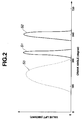
- Fig. 2 which depicts the relationship between valve lift (amount) and an operational cycle or crankangle of the engine in this embodiment.
- a solid curve indicates the valve timings of the intake valve 6, while a broken curve indicates the valve timings of the exhaust valve 8.
- an opening and closing action of the intake valve 6 is made twice in an intake stroke of the engine E.
- first and second opening and closing actions (or first and second air intakes) of the intake valve 6 is made in the intake stroke.
- a solid curve S1 indicates the first opening and closing action
- a solid curve S2 indicates the second opening and closing action
- a broken curve S3 indicates an opening and closing action of the exhaust valve 8.
- the first opening (forming part of the first opening and closing action) of the intake valve 6 is initiated after the closing of the exhaust valve 8 and at the initial period of the intake stroke.
- the first opening of the intake valve 6 is maintained throughout a duration (first opening duration) of 60° in crankangle.
- the first closing (forming part of the first opening and closing action) of the intake valve 6 is completed.
- the second opening (forming part of the second opening and closing action) of the intake valve 6 is initiated at a timing which is 60° in crankangle after the completion of the first closing of the intake valve 6.
- the second opening of the intake valve 6 is maintained throughout a duration (first opening duration) of 90° in crankangle.
- the second closing (forming part of the second opening and closing action) of the intake valve 6 is completed.
- the first opening of the intake valve 6 is made in timed relation to the initiation of the intake stroke as conventional, and the first closing of the intake valve 6 is made in synchronism with (in timed relation to) intake air pulsation in the intake port 5.
- the second opening and closing action of the intake valve 6 are also made in synchronism with the intake air pulsation.
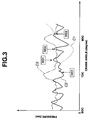
- Fig. 3 depicts variations in in-cylinder pressure (pressure inside the combustion chamber or cylinder), intake air pressure (pressure of intake air outside the combustion chamber) and exhaust gas pressure (pressure of exhaust gas outside the combustion chamber 4).
- the in-cylinder pressure is indicated by a curve C1; the intake air pressure is indicated by a curve C2; and the exhaust gas pressure is indicated by a curve C3.
- Fig. 3 depicts variations in in-cylinder pressure (pressure inside the combustion chamber or cylinder), intake air pressure (pressure of intake air outside the combustion chamber) and exhaust gas pressure (pressure of exhaust gas outside the combustion chamber 4).
- the in-cylinder pressure is indicated by a curve C1; the intake
- IVO1 and IVC1 represent respectively the first opening and the first closing (in the first opening and closing action) of the intake valve 6; and “IVO2" and “IVC2” represent respectively the second opening and the second closing (in the second opening and closing action) of the intake valve 6.
- the first opening of the intake valve 6 is initiated immediately after the top dead center (TDC), and the first closing of the intake valve 6 is completed or terminated at a timing (represented by "IVC1") at which the intake air pressure has reached to the highest level.
- TDC top dead center
- IVC1 a timing at which the intake air pressure has reached to the highest level.
- gas within the intake port 5 is sucked into the combustion chamber 4 so that gas flow toward the combustion chamber 4 is generated.
- the first opening and closing action of the intake valve 6 is terminated, and therefore the gas flow within the intake port 5 is interrupted by closing the intake valve 6 so that the intake air pressure wave is reflected. This amplifies the intake air pulsation.
- the intake air pressure is temporarily lowered under the action of wave motion of the intake air pressure wave, and then again starts to rise under the action of the intake air pulsation.
- the second opening of the intake valve 6 is initiated at a timing (represented by "IVO2") at which the difference in pressure between the inside and outside of the cylinder (combustion chamber) increases owing to lowering in the in-cylinder pressure upon downward movement of the piston 2.
- the piston 2 reaches the bottom dead center (BDC), and the second closing of the intake valve 6 is terminated immediately before the in-cylinder pressure rises over the intake air pressure (or at a timing represented by "IVC2").
- a duration in which the first and second opening and closing actions of the intake valve are made is not limited to a crankangle range of from 360° to 540°.
- Fig. 4 depicts a volumetric efficiency in terms of mass flow (kg) of intake air, in the intake stroke where two (first and second) air intakes are accomplished respectively by the first and second opening and closing actions of the intake valve.
- a curve M1 represents a variation in mass flow of the intake air in this embodiment of the present invention
- a curve M2 represents a variation in mass flow of the intake air in a conventional, technique in which air intake is made only once in the intake stroke.
- the intake air amount per unit time i.e., an inclination of the curve of mass flow
- the internal combustion engine E of this embodiment is the same in construction as that of the first embodiment but slightly different in control for the intake valve 6. Accordingly, the combustion chamber 4 is defined in the cylinder 1a and between the piston 2 and the cylinder head 3.
- the cylinder head 3 is provided with the intake and exhaust valves 6, 8 which are electromagnetically operated respectively by the actuators 12, 13. Additionally, the cylinder head 3 is provided with the fuel injector valve 9 and the spark plug 10.
- the actuators 12, 13, the fuel injector valve 9 and the spark plug 10 are controlled by the engine control unit 11.
- air intake to the cylinder is accomplished twice in the intake stroke in such a manner that an opening area of the intake valve 6 in the second air intake (or the second opening and closing action of the intake valve) becomes larger than that in the first air intake (or the first opening and closing action), i.e., the valve lift (amount) in the second air intake becomes larger than that in the first air intake.
- the opening area is an area of an imaginary generally frustoconical face F which imaginarily lies between a valve face 6a of the opened intake valve 6 (at the maximum valve lift) and a valve seat 3a fixed to the cylinder head 3 and located at such a position as to connect the shortest distance between the valve face 6a and the valve 3a.
- straight lines Fa, Fb corresponding to the generally frustoconical face F on a cross-sectional plane shown in Fig. 10A connect the valve seat 3a and the valve seat 3a at the shortest distance.
- the engine control unit 11 is arranged to control operation of the actuator 12 in such a manner that the valve lift (amount) in the second air intake is about two times of that in the first air intake.
- Fig. 5 depicts the relationship (or so-called valve lift sensitivity) between the amount (mass flow) of intake air to be sucked into the cylinder and the valve lift (amount) of the intake valve.
- the mass flow corresponds to a flow amount of intake air per second (kg/sec.)
- a line N1 indicates the valve lift sensitivity of the first air intake
- a line N2 indicates the valve lift sensitivity of the second air intake.
- the mass flow takes the value of W2-1 at the valve lift L1, and takes the value of W2-2 when the valve lift is increased to L2.
- the valve lift sensitivity is taken to its peak value by decreasing the valve lift (amount) of the intake valve in the first air intake. Additionally, the opening area of the intake valve is increased as large as possible by increasing the valve lift of the intake valve in the second air intake. According to this operation, decreasing the valve lift in the first air intake reduces an unnecessary valve lift (amount), thereby lowering an electric power supplied to the electromagnetic actuator and required for actuation of the intake valve.
- a third embodiment of the internal combustion engine E according to the present invention will be discussed with reference to Figs. 6A to 7B.
- the engine E of this embodiment is similar in construction to that of the second and third embodiments with the exception that a plurality of intake valves 61, 62, 63 and a plurality of exhaust valves 8, 8 are provided for each cylinder (combustion chamber).
- the total opening area of the intake valves in the second air intake becomes larger than that of the intake valve in the first air intake. This is realized by increasing the number of the intake valves to be opened in the second air intake relative to that of the intake valve(s) to be opened in the first air intake.
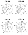
- Figs. 6A and 6B show a part of a four valve type engine E in which two intake valves 61, 62 and two exhaust valves 8, 8 are provided for each cylinder, constituting an example of this embodiment.
- one (oblique-lined) 61 of the two intake valves 61, 62 is opened in the first air intake as shown in Fig. 6A while the two intake valves 61, 62 are opened in the second air intake as shown in Fig. 6B.
- the intake valves 61 is opened for a time duration corresponding to the above-mentioned first opening and closing action; and the two intake valves 61, 62 are opened for a time duration corresponding to the above-mentioned second opening and closing action.
- the opening area of the intake valve (2) is a total of the opening area(s) of the opened intake valve(s).
- the opening area may be a total of the cross-sectional area(s) of the valve head(s) of the opened intake valve(s), the cross-sectional area being on a cross-sectional plane perpendicular to the axis of the intake valve.
- Fig. 8 depicts effects of generating swirl flow or tumble flow of intake air in terms of swirl ratio or tumble ratio, in cases of engine operation modes in which one or two intake valves are opened.
- the swirl ratio is represented by [a flow speed (m/sec.) of gas in a tangential direction of the cylinder bore / a flow speed (m/sec.) of gas in an axial direction of the cylinder bore].
- the tumble ratio is represented by [a flow speed (m/sec.) of tumble flow of gas in an axial direction of the cylinder bore / a flow speed (m/sec.) of gas in an axial direction of the cylinder bore].
- a line R1 represents a variation in swirl ratio in case of an engine operation mode in which only the right-side intake valve 61 is opened in intake stroke.
- a line R2 represents a variation in tumble ratio in case of an engine operation mode in which the two intake valves 61, 62 are opened in intake stroke.
- a line R3 represents a variation in tumble ratio in case of an engine operation mode in which only the right-side intake valve 61 is opened in intake stroke. It will be understood that the swirl ratio is about 0 in case of an engine operation mode in which both the intake valves 61, 62 are closed, and therefore the swirl ratio variation in such a case is not shown in Fig. 8.
- Figs. 7A and 7B show a part of a five valve type engine in which three intake valves 61, 62, 63 and two exhaust valves 8, 8 are provided for each cylinder, constituting another example of this embodiment.
- one (oblique-lined) 61 of the three intake valves 61, 62, 63 is opened in the first air intake as shown in Fig. 7A while the three intake valves 61, 62, 63 are opened in the second air intake as shown in Fig. 7B.
- the intake valves 61, 62 or the intake valves 61, 63 may be opened in the first air intake, while all the three intake valves 61, 62, 63 may be opened in the second air intake.
- a fourth embodiment of the internal combustion engine E according to the present invention will be discussed with reference to Fig. 9.
- the engine E of this embodiment is the same in construction as that of the first embodiment but slightly different in control for the intake valve 6. That is, in this embodiment, the first and second air intakes (made also in the first and second embodiments) made only in a predetermined low engine speed range of the engine E.
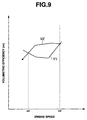
- Fig. 9 depicts comparison in volumetric efficiency ( ⁇ v) made between the engine operation mode (indicated by a line V1) carrying out only one air intake in intake stroke and the engine operation mode (indicated by a line V2) carrying out the first and second air intakes in intake stroke.
- the volumetric efficiency In a low engine speed range lower than a first predetermined engine speed n1, the volumetric efficiency is higher in the former engine operation mode. However, in an engine speed range between the first predetermined engine speed n1 and a second predetermined engine speed n2, the volumetric efficiency is higher in the latter engine operation mode than in the former engine operation mode. In an engine speed range over the second predetermined engine speed n2, the volumetric efficiency is higher in the former engine operation mode than in the latter engine operation mode.
- the first and second air intakes in intake stroke are carried out only in the predetermined engine speed range between the first and second predetermined engine speeds n1, n2. Only one air intake in intake stroke is carried out in the engine speed ranges lower than the first predetermined engine speed n1 and higher than the second predetermined engine speed n2.
- control manners of the intake valves are changed in accordance with engine speed.
- the first predetermined engine speed n1 is about 1000 r.p.m. while the second predetermined engine speed n2 is about 2500 r.p.m.
- the engine operation mode carrying out the only one air intake and the engine operation mode carrying out the first and second air intakes are changed over in accordance with engine speed of the engine E, thereby effectively improving the volumetric efficiency of the engine E.
- control manners of the intake valve of the fourth embodiment have been applied to the engine of the first embodiment, it will be understood that the same control manners of the intake valve(s) may be applied to the engines of the second and third embodiments.
- the intake valve(s) is electromagnetically operated to make two (first and second) opening and closing actions in an intake stroke in synchronism with intake air pulsation.
- the first opening and closing action of the intake valve amplitudes the intake air pulsation thereby increasing the pressure differential between the inside and the outside of the combustion chamber.
- air intake into the combustion chamber can be effectively accomplished by the second opening and closing action of the intake valve under the effect of the pressure differential.
- the volumetric efficiency of the engine can be largely improved without applying a structural change to a conventional internal combustion engine while avoiding making the engine large-sized. This can also improve the combustion efficiency of the engine.
Landscapes
- Engineering & Computer Science (AREA)
- Mechanical Engineering (AREA)
- General Engineering & Computer Science (AREA)
- Chemical & Material Sciences (AREA)
- Combustion & Propulsion (AREA)
- Valve Device For Special Equipments (AREA)
- Output Control And Ontrol Of Special Type Engine (AREA)
- Characterised By The Charging Evacuation (AREA)
- Control Of Throttle Valves Provided In The Intake System Or In The Exhaust System (AREA)
Applications Claiming Priority (2)
| Application Number | Priority Date | Filing Date | Title |
|---|---|---|---|
| JP11180453A JP2001012264A (ja) | 1999-06-25 | 1999-06-25 | 内燃機関 |
| JP18045399 | 1999-06-25 |
Publications (3)
| Publication Number | Publication Date |
|---|---|
| EP1063394A2 true EP1063394A2 (de) | 2000-12-27 |
| EP1063394A3 EP1063394A3 (de) | 2001-04-25 |
| EP1063394B1 EP1063394B1 (de) | 2004-12-15 |
Family
ID=16083500
Family Applications (1)
| Application Number | Title | Priority Date | Filing Date |
|---|---|---|---|
| EP00113277A Expired - Lifetime EP1063394B1 (de) | 1999-06-25 | 2000-06-21 | Verbrennungskraftmaschine |
Country Status (4)
| Country | Link |
|---|---|
| US (1) | US6311653B1 (de) |
| EP (1) | EP1063394B1 (de) |
| JP (1) | JP2001012264A (de) |
| DE (1) | DE60016669T2 (de) |
Cited By (10)
| Publication number | Priority date | Publication date | Assignee | Title |
|---|---|---|---|---|
| EP1431526A1 (de) * | 2002-12-20 | 2004-06-23 | Ford Global Technologies, Inc. | Verfahren zur Einlasstaktsteuerung in einer Brennkraftmaschine |
| WO2006117486A1 (fr) * | 2005-05-03 | 2006-11-09 | Peugeot Citroën Automobiles SA | Procédé de réduction des émissions d'hydrocarbures d'un moteur froid et dispositif et moteur mettant en oeuvre ce procédé |
| DE10234103B4 (de) * | 2002-07-26 | 2008-02-14 | Daimler Ag | Verfahren zur Steuerung eines Einlassventils |
| WO2012085450A1 (fr) * | 2010-12-22 | 2012-06-28 | Valeo Systemes De Controle Moteur | Procede de commande d'au moins une soupape d'admission d'un moteur thermique fonctionnant selon un cycle a quatre temps |
| IT202200025410A1 (it) * | 2022-12-13 | 2024-06-13 | Fiat Ricerche | "Motore a combustione interna con azionamento variabile delle valvole di aspirazione e procedimento di controllo del motore" |
| WO2024127137A1 (en) | 2022-12-13 | 2024-06-20 | C.R.F. Società Consortile Per Azioni | Internal combustion engine with improved intake valve opening strategies and engine control method |
| IT202300003450A1 (it) * | 2023-02-27 | 2024-08-27 | Fiat Ricerche | "motore a combustione interna con azionamento variabile delle valvole di aspirazione e procedimento di controllo del motore" |
| IT202300013266A1 (it) * | 2023-06-27 | 2024-12-27 | Fiat Ricerche | "motore a combustione interna con azionamento variabile delle valvole di aspirazione, con controllo perfezionato in condizioni di avviamento a freddo" |
| WO2025181590A1 (en) * | 2024-02-27 | 2025-09-04 | C.R.F. Società Consortile Per Azioni | Internal combustion engine with variable actuation intake valves and with cylinders controlled to operate independently with ultra-lean combustion or stoichiometric combustion, and a control method therefor |
| WO2025248339A1 (en) * | 2024-05-28 | 2025-12-04 | C.R.F. Società Consortile Per Azioni | Internal combustion engine with air jet system for cylinder filling, and method for controlling the engine |
Families Citing this family (20)
| Publication number | Priority date | Publication date | Assignee | Title |
|---|---|---|---|---|
| FR2815082B1 (fr) * | 2000-10-09 | 2003-04-11 | Inst Francais Du Petrole | Procede de controle d'auto-allumage dans un moteur a quatre temps |
| US6886533B2 (en) * | 2003-01-03 | 2005-05-03 | Ford Global Technologies, Llc | Internal combustion engine with multiple intake valves and variable valve actuation and timing |
| US7093568B2 (en) * | 2003-01-13 | 2006-08-22 | Ford Global Technologies, Llc | Control of autoignition timing in a HCCI engine |
| FR2852359B1 (fr) * | 2003-03-12 | 2005-05-20 | Procede de commande des soupapes d'un moteur a combustion interne | |
| JP4054711B2 (ja) * | 2003-04-21 | 2008-03-05 | 株式会社日立製作所 | 可変動弁式内燃機関 |
| JP4209317B2 (ja) * | 2003-12-18 | 2009-01-14 | 三菱重工業株式会社 | 内燃機関の排気浄化装置 |
| US6959689B1 (en) * | 2004-07-08 | 2005-11-01 | Ford Global Technologies, Llc | Engine expansion braking with adjustable valve timing |
| FR2872860B1 (fr) * | 2004-07-12 | 2008-03-28 | Peugeot Citroen Automobiles Sa | Procede ameliore de commande d'un moteur a combustion interne, en vue de diminuer les emissions de polluants, moteur fonctionnant selon un tel procede, et vehicule automobile equipe d'un tel moteur |
| US7152559B2 (en) * | 2004-07-26 | 2006-12-26 | General Motors Corporation | Valve and fueling strategy for operating a controlled auto-ignition four-stroke internal combustion engine |
| US7150250B2 (en) * | 2004-07-26 | 2006-12-19 | General Motors Corporation | Valve and fueling strategy for operating a controlled auto-ignition four-stroke internal combustion engine |
| US7128047B2 (en) * | 2004-07-26 | 2006-10-31 | General Motors Corporation | Valve and fueling strategy for operating a controlled auto-ignition four-stroke internal combustion engine |
| US7137381B1 (en) * | 2005-04-13 | 2006-11-21 | Ricardo, Inc. | Indirect variable valve actuation for an internal combustion engine |
| ES2296094T3 (es) * | 2005-05-24 | 2008-04-16 | C.R.F. Societa' Consortile Per Azioni | Sistema y procedimiento para controlar la carga y la combustion en un motor de combustion interna mediante el accionamiento de valvula segun un ciclo de elevacion multiple (multielevacion). |
| DE102005031241A1 (de) * | 2005-07-01 | 2007-01-04 | Fev Motorentechnik Gmbh | Variabler Ventiltrieb einer Kolben-Brennkraftmaschine |
| US7685976B2 (en) * | 2006-03-24 | 2010-03-30 | Gm Global Technology Operations, Inc. | Induction tuning using multiple intake valve lift events |
| US7832370B2 (en) * | 2006-11-16 | 2010-11-16 | Gm Global Technology Operations, Inc. | Low-load operation extension of a homogeneous charge compression ignition engine |
| JP4872885B2 (ja) * | 2007-11-05 | 2012-02-08 | トヨタ自動車株式会社 | 内燃機関 |
| GB2519334A (en) * | 2013-10-17 | 2015-04-22 | Barrus E P Ltd | A marine propulsion unit and a valve for a marine propulsion unit |
| JP6488877B2 (ja) * | 2015-05-18 | 2019-03-27 | いすゞ自動車株式会社 | 内燃機関 |
| US11585284B1 (en) * | 2021-07-29 | 2023-02-21 | Ford Global Technologies, Llc | Methods for re-combustion in engines |
Citations (2)
| Publication number | Priority date | Publication date | Assignee | Title |
|---|---|---|---|---|
| EP0508159A2 (de) | 1991-04-06 | 1992-10-14 | FEV Motorentechnik GmbH & Co. KG | Einlasssteuerung für Verbrennungskraftmaschinen |
| JPH05157008A (ja) | 1991-11-29 | 1993-06-22 | Mazda Motor Corp | エンジン |
Family Cites Families (6)
| Publication number | Priority date | Publication date | Assignee | Title |
|---|---|---|---|---|
| US4829947A (en) * | 1987-08-12 | 1989-05-16 | General Motors Corporation | Variable lift operation of bistable electromechanical poppet valve actuator |
| US5216987A (en) | 1992-06-01 | 1993-06-08 | Caterpillar Inc. | Method and apparatus for optimizing breathing utilizing unit valve actuation |
| US5327856A (en) * | 1992-12-22 | 1994-07-12 | General Motors Corporation | Method and apparatus for electrically driving engine valves |
| JPH07301105A (ja) | 1994-05-06 | 1995-11-14 | Honda Motor Co Ltd | 内燃機関の動弁装置 |
| WO1997013063A1 (en) * | 1995-10-02 | 1997-04-10 | Hitachi, Ltd. | Control device for an internal combustion engine |
| DE19733139A1 (de) | 1997-07-31 | 1999-02-04 | Fev Motorentech Gmbh & Co Kg | Verfahren zur Beeinflussung von Gemischbildung und Ladungsbewegung in einem Zylinder einer fremdgezündeten Kolbenbrennkraftmaschine |
-
1999
- 1999-06-25 JP JP11180453A patent/JP2001012264A/ja active Pending
-
2000
- 2000-06-21 US US09/598,834 patent/US6311653B1/en not_active Expired - Fee Related
- 2000-06-21 EP EP00113277A patent/EP1063394B1/de not_active Expired - Lifetime
- 2000-06-21 DE DE60016669T patent/DE60016669T2/de not_active Expired - Fee Related
Patent Citations (2)
| Publication number | Priority date | Publication date | Assignee | Title |
|---|---|---|---|---|
| EP0508159A2 (de) | 1991-04-06 | 1992-10-14 | FEV Motorentechnik GmbH & Co. KG | Einlasssteuerung für Verbrennungskraftmaschinen |
| JPH05157008A (ja) | 1991-11-29 | 1993-06-22 | Mazda Motor Corp | エンジン |
Cited By (14)
| Publication number | Priority date | Publication date | Assignee | Title |
|---|---|---|---|---|
| DE10234103B4 (de) * | 2002-07-26 | 2008-02-14 | Daimler Ag | Verfahren zur Steuerung eines Einlassventils |
| EP1431526A1 (de) * | 2002-12-20 | 2004-06-23 | Ford Global Technologies, Inc. | Verfahren zur Einlasstaktsteuerung in einer Brennkraftmaschine |
| WO2006117486A1 (fr) * | 2005-05-03 | 2006-11-09 | Peugeot Citroën Automobiles SA | Procédé de réduction des émissions d'hydrocarbures d'un moteur froid et dispositif et moteur mettant en oeuvre ce procédé |
| FR2885389A1 (fr) * | 2005-05-03 | 2006-11-10 | Peugeot Citroen Automobiles Sa | Procede de reduction des emissions d'hydrocarbures d'un moteur froid et dispositif et moteur mettant en oeuvre ce procede |
| WO2012085450A1 (fr) * | 2010-12-22 | 2012-06-28 | Valeo Systemes De Controle Moteur | Procede de commande d'au moins une soupape d'admission d'un moteur thermique fonctionnant selon un cycle a quatre temps |
| FR2972219A1 (fr) * | 2010-12-22 | 2012-09-07 | Valeo Sys Controle Moteur Sas | Procede de commande d'au moins une soupape d'admission d'un moteur thermique fonctionnant selon un cycle a quatre temps. |
| IT202200025410A1 (it) * | 2022-12-13 | 2024-06-13 | Fiat Ricerche | "Motore a combustione interna con azionamento variabile delle valvole di aspirazione e procedimento di controllo del motore" |
| WO2024127136A1 (en) | 2022-12-13 | 2024-06-20 | C.R.F. Società Consortile Per Azioni | Internal combustion engine with variable intake valve actuation and engine control method |
| WO2024127137A1 (en) | 2022-12-13 | 2024-06-20 | C.R.F. Società Consortile Per Azioni | Internal combustion engine with improved intake valve opening strategies and engine control method |
| IT202300003450A1 (it) * | 2023-02-27 | 2024-08-27 | Fiat Ricerche | "motore a combustione interna con azionamento variabile delle valvole di aspirazione e procedimento di controllo del motore" |
| WO2024180392A1 (en) | 2023-02-27 | 2024-09-06 | C.R.F. Società Consortile Per Azioni | Internal combustion engine with variable intake valve actuation and engine control method |
| IT202300013266A1 (it) * | 2023-06-27 | 2024-12-27 | Fiat Ricerche | "motore a combustione interna con azionamento variabile delle valvole di aspirazione, con controllo perfezionato in condizioni di avviamento a freddo" |
| WO2025181590A1 (en) * | 2024-02-27 | 2025-09-04 | C.R.F. Società Consortile Per Azioni | Internal combustion engine with variable actuation intake valves and with cylinders controlled to operate independently with ultra-lean combustion or stoichiometric combustion, and a control method therefor |
| WO2025248339A1 (en) * | 2024-05-28 | 2025-12-04 | C.R.F. Società Consortile Per Azioni | Internal combustion engine with air jet system for cylinder filling, and method for controlling the engine |
Also Published As
| Publication number | Publication date |
|---|---|
| EP1063394A3 (de) | 2001-04-25 |
| US6311653B1 (en) | 2001-11-06 |
| DE60016669D1 (de) | 2005-01-20 |
| JP2001012264A (ja) | 2001-01-16 |
| DE60016669T2 (de) | 2005-10-06 |
| EP1063394B1 (de) | 2004-12-15 |
Similar Documents
| Publication | Publication Date | Title |
|---|---|---|
| US6311653B1 (en) | Internal combustion engine | |
| US5269270A (en) | Four-stroke cycle internal-combustion engine | |
| EP1857654B1 (de) | Verbrennungsmotor | |
| US6260520B1 (en) | Homogeneous charge compression ignition internal combustion engine | |
| US5454356A (en) | Engine with pre-chamber | |
| EP1566528B1 (de) | Brennkraftmaschine | |
| US7004116B2 (en) | Four stroke auto-ignition engine | |
| WO2001046572A1 (en) | A four stroke engine | |
| US20120283932A1 (en) | Two-stroke internal combustion engine with variable compression ratio and an exhaust port shutter and a method of operating such an engine | |
| KR20010093780A (ko) | 내연기관의 연소과정을 제어하는 방법 및 실린더의 유효압축비를 변화시키기 위한 수단을 구비한 엔진 | |
| JPH03264747A (ja) | 2行程サイクルエンジン | |
| US6318308B1 (en) | Increased compression ratio diesel engine assembly for retarded fuel injection timing | |
| JP4731491B2 (ja) | 燃焼制御の均質給気圧縮点火開始方法 | |
| US6910459B2 (en) | HCCI engine with combustion-tailoring chamber | |
| US6539909B2 (en) | Retractable seat valve and method for selective gas flow control in a combustion chamber | |
| JP3695019B2 (ja) | 副室容積可変式ガスエンジン | |
| JPH04303121A (ja) | 2ストロークエンジン | |
| US20180252155A1 (en) | Selective cycle engine with sidewall valve | |
| EP4562283B1 (de) | Fremdgezündete brennkraftmaschine mit verdünnter ladung und verfahren zu ihrer steuerung | |
| JP4223987B2 (ja) | 爆発行程が圧縮行程より長い直噴4サイクルエンジン | |
| JP2005023831A (ja) | 内燃機関 | |
| JP2005226583A (ja) | 内燃機関の動弁制御方法 | |
| GB2393758A (en) | An auto-ignited homogeneous charge four stroke engine | |
| JP2007187046A (ja) | 可変圧縮比内燃機関 |
Legal Events
| Date | Code | Title | Description |
|---|---|---|---|
| PUAI | Public reference made under article 153(3) epc to a published international application that has entered the european phase |
Free format text: ORIGINAL CODE: 0009012 |
|
| 17P | Request for examination filed |
Effective date: 20000621 |
|
| AK | Designated contracting states |
Kind code of ref document: A2 Designated state(s): AT BE CH CY DE DK ES FI FR GB GR IE IT LI LU MC NL PT SE |
|
| AX | Request for extension of the european patent |
Free format text: AL;LT;LV;MK;RO;SI |
|
| PUAL | Search report despatched |
Free format text: ORIGINAL CODE: 0009013 |
|
| AK | Designated contracting states |
Kind code of ref document: A3 Designated state(s): AT BE CH CY DE DK ES FI FR GB GR IE IT LI LU MC NL PT SE |
|
| AX | Request for extension of the european patent |
Free format text: AL;LT;LV;MK;RO;SI |
|
| AKX | Designation fees paid |
Free format text: DE FR GB |
|
| 17Q | First examination report despatched |
Effective date: 20020402 |
|
| TPAC | Observations filed by third parties |
Free format text: ORIGINAL CODE: EPIDOSNTIPA |
|
| GRAP | Despatch of communication of intention to grant a patent |
Free format text: ORIGINAL CODE: EPIDOSNIGR1 |
|
| GRAS | Grant fee paid |
Free format text: ORIGINAL CODE: EPIDOSNIGR3 |
|
| GRAA | (expected) grant |
Free format text: ORIGINAL CODE: 0009210 |
|
| AK | Designated contracting states |
Kind code of ref document: B1 Designated state(s): DE FR GB |
|
| REG | Reference to a national code |
Ref country code: GB Ref legal event code: FG4D |
|
| REF | Corresponds to: |
Ref document number: 60016669 Country of ref document: DE Date of ref document: 20050120 Kind code of ref document: P |
|
| PLBE | No opposition filed within time limit |
Free format text: ORIGINAL CODE: 0009261 |
|
| STAA | Information on the status of an ep patent application or granted ep patent |
Free format text: STATUS: NO OPPOSITION FILED WITHIN TIME LIMIT |
|
| ET | Fr: translation filed | ||
| 26N | No opposition filed |
Effective date: 20050916 |
|
| PGFP | Annual fee paid to national office [announced via postgrant information from national office to epo] |
Ref country code: DE Payment date: 20070614 Year of fee payment: 8 |
|
| PGFP | Annual fee paid to national office [announced via postgrant information from national office to epo] |
Ref country code: GB Payment date: 20070620 Year of fee payment: 8 |
|
| PGFP | Annual fee paid to national office [announced via postgrant information from national office to epo] |
Ref country code: FR Payment date: 20070608 Year of fee payment: 8 |
|
| GBPC | Gb: european patent ceased through non-payment of renewal fee |
Effective date: 20080621 |
|
| REG | Reference to a national code |
Ref country code: FR Ref legal event code: ST Effective date: 20090228 |
|
| PG25 | Lapsed in a contracting state [announced via postgrant information from national office to epo] |
Ref country code: DE Free format text: LAPSE BECAUSE OF NON-PAYMENT OF DUE FEES Effective date: 20090101 |
|
| PG25 | Lapsed in a contracting state [announced via postgrant information from national office to epo] |
Ref country code: GB Free format text: LAPSE BECAUSE OF NON-PAYMENT OF DUE FEES Effective date: 20080621 |
|
| PG25 | Lapsed in a contracting state [announced via postgrant information from national office to epo] |
Ref country code: FR Free format text: LAPSE BECAUSE OF NON-PAYMENT OF DUE FEES Effective date: 20080630 |