EP1063467A2 - Procédé et dispositif d' éclairage - Google Patents
Procédé et dispositif d' éclairage Download PDFInfo
- Publication number
- EP1063467A2 EP1063467A2 EP00305279A EP00305279A EP1063467A2 EP 1063467 A2 EP1063467 A2 EP 1063467A2 EP 00305279 A EP00305279 A EP 00305279A EP 00305279 A EP00305279 A EP 00305279A EP 1063467 A2 EP1063467 A2 EP 1063467A2
- Authority
- EP
- European Patent Office
- Prior art keywords
- media
- ring
- assembly
- lamp
- locking
- Prior art date
- Legal status (The legal status is an assumption and is not a legal conclusion. Google has not performed a legal analysis and makes no representation as to the accuracy of the status listed.)
- Withdrawn
Links
- 238000000034 method Methods 0.000 title claims description 15
- 238000010079 rubber tapping Methods 0.000 description 3
- 125000006850 spacer group Chemical group 0.000 description 3
- 238000009434 installation Methods 0.000 description 1
- 238000000926 separation method Methods 0.000 description 1
Images




Classifications
-
- F—MECHANICAL ENGINEERING; LIGHTING; HEATING; WEAPONS; BLASTING
- F21—LIGHTING
- F21S—NON-PORTABLE LIGHTING DEVICES; SYSTEMS THEREOF; VEHICLE LIGHTING DEVICES SPECIALLY ADAPTED FOR VEHICLE EXTERIORS
- F21S8/00—Lighting devices intended for fixed installation
- F21S8/02—Lighting devices intended for fixed installation of recess-mounted type, e.g. downlighters
-
- F—MECHANICAL ENGINEERING; LIGHTING; HEATING; WEAPONS; BLASTING
- F21—LIGHTING
- F21S—NON-PORTABLE LIGHTING DEVICES; SYSTEMS THEREOF; VEHICLE LIGHTING DEVICES SPECIALLY ADAPTED FOR VEHICLE EXTERIORS
- F21S8/00—Lighting devices intended for fixed installation
- F21S8/02—Lighting devices intended for fixed installation of recess-mounted type, e.g. downlighters
- F21S8/026—Lighting devices intended for fixed installation of recess-mounted type, e.g. downlighters intended to be recessed in a ceiling or like overhead structure, e.g. suspended ceiling
-
- F—MECHANICAL ENGINEERING; LIGHTING; HEATING; WEAPONS; BLASTING
- F21—LIGHTING
- F21V—FUNCTIONAL FEATURES OR DETAILS OF LIGHTING DEVICES OR SYSTEMS THEREOF; STRUCTURAL COMBINATIONS OF LIGHTING DEVICES WITH OTHER ARTICLES, NOT OTHERWISE PROVIDED FOR
- F21V17/00—Fastening of component parts of lighting devices, e.g. shades, globes, refractors, reflectors, filters, screens, grids or protective cages
- F21V17/10—Fastening of component parts of lighting devices, e.g. shades, globes, refractors, reflectors, filters, screens, grids or protective cages characterised by specific fastening means or way of fastening
- F21V17/12—Fastening of component parts of lighting devices, e.g. shades, globes, refractors, reflectors, filters, screens, grids or protective cages characterised by specific fastening means or way of fastening by screwing
-
- F—MECHANICAL ENGINEERING; LIGHTING; HEATING; WEAPONS; BLASTING
- F21—LIGHTING
- F21V—FUNCTIONAL FEATURES OR DETAILS OF LIGHTING DEVICES OR SYSTEMS THEREOF; STRUCTURAL COMBINATIONS OF LIGHTING DEVICES WITH OTHER ARTICLES, NOT OTHERWISE PROVIDED FOR
- F21V17/00—Fastening of component parts of lighting devices, e.g. shades, globes, refractors, reflectors, filters, screens, grids or protective cages
- F21V17/10—Fastening of component parts of lighting devices, e.g. shades, globes, refractors, reflectors, filters, screens, grids or protective cages characterised by specific fastening means or way of fastening
- F21V17/14—Bayonet-type fastening
-
- F—MECHANICAL ENGINEERING; LIGHTING; HEATING; WEAPONS; BLASTING
- F21—LIGHTING
- F21V—FUNCTIONAL FEATURES OR DETAILS OF LIGHTING DEVICES OR SYSTEMS THEREOF; STRUCTURAL COMBINATIONS OF LIGHTING DEVICES WITH OTHER ARTICLES, NOT OTHERWISE PROVIDED FOR
- F21V17/00—Fastening of component parts of lighting devices, e.g. shades, globes, refractors, reflectors, filters, screens, grids or protective cages
- F21V17/10—Fastening of component parts of lighting devices, e.g. shades, globes, refractors, reflectors, filters, screens, grids or protective cages characterised by specific fastening means or way of fastening
- F21V17/16—Fastening of component parts of lighting devices, e.g. shades, globes, refractors, reflectors, filters, screens, grids or protective cages characterised by specific fastening means or way of fastening by deformation of parts; Snap action mounting
- F21V17/162—Fastening of component parts of lighting devices, e.g. shades, globes, refractors, reflectors, filters, screens, grids or protective cages characterised by specific fastening means or way of fastening by deformation of parts; Snap action mounting the parts being subjected to traction or compression, e.g. coil springs
-
- F—MECHANICAL ENGINEERING; LIGHTING; HEATING; WEAPONS; BLASTING
- F21—LIGHTING
- F21V—FUNCTIONAL FEATURES OR DETAILS OF LIGHTING DEVICES OR SYSTEMS THEREOF; STRUCTURAL COMBINATIONS OF LIGHTING DEVICES WITH OTHER ARTICLES, NOT OTHERWISE PROVIDED FOR
- F21V17/00—Fastening of component parts of lighting devices, e.g. shades, globes, refractors, reflectors, filters, screens, grids or protective cages
- F21V17/10—Fastening of component parts of lighting devices, e.g. shades, globes, refractors, reflectors, filters, screens, grids or protective cages characterised by specific fastening means or way of fastening
- F21V17/16—Fastening of component parts of lighting devices, e.g. shades, globes, refractors, reflectors, filters, screens, grids or protective cages characterised by specific fastening means or way of fastening by deformation of parts; Snap action mounting
- F21V17/168—Fastening of component parts of lighting devices, e.g. shades, globes, refractors, reflectors, filters, screens, grids or protective cages characterised by specific fastening means or way of fastening by deformation of parts; Snap action mounting the parts being resilient rings acting substantially isotropically, e.g. split rings
-
- F—MECHANICAL ENGINEERING; LIGHTING; HEATING; WEAPONS; BLASTING
- F21—LIGHTING
- F21V—FUNCTIONAL FEATURES OR DETAILS OF LIGHTING DEVICES OR SYSTEMS THEREOF; STRUCTURAL COMBINATIONS OF LIGHTING DEVICES WITH OTHER ARTICLES, NOT OTHERWISE PROVIDED FOR
- F21V19/00—Fastening of light sources or lamp holders
-
- F—MECHANICAL ENGINEERING; LIGHTING; HEATING; WEAPONS; BLASTING
- F21—LIGHTING
- F21V—FUNCTIONAL FEATURES OR DETAILS OF LIGHTING DEVICES OR SYSTEMS THEREOF; STRUCTURAL COMBINATIONS OF LIGHTING DEVICES WITH OTHER ARTICLES, NOT OTHERWISE PROVIDED FOR
- F21V21/00—Supporting, suspending, or attaching arrangements for lighting devices; Hand grips
- F21V21/14—Adjustable mountings
- F21V21/30—Pivoted housings or frames
Definitions
- the present invention pertains to a lighting apparatus.
- the lighting apparatus comprises a yoke.
- the apparatus comprises a lamp ring for holding a lamp.
- the lamp ring is connected to the mounting structure.
- the apparatus comprises a ring locking mechanism for locking the lamp ring in a fixed position relative to the yoke.
- Figure 2 is a bottom view of a lighting apparatus of the present invention.
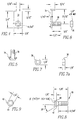
- Figure 6 is a side view of a locking clip with threaded stud or screw.
- Figure 19 is a schematic representation of an exploded view of a self-tapping screw and a spacer.
- the locking nut 38 can have a locking head 42 with holes 44 which receive a tool, such as an Allen wrench, to facilitate tightening or loosening of the second threaded screw or stud 36.
- the inner nut 38 can have an inner head 46 with holes 44 for the same purpose to facilitate tightening or loosening.
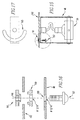
- the yoke 48 can be locked in place to the housing 162 with a yoke screw 157 that extends throughout a yoke hole 159 and threads into a bushing mechanism 161 that clamps to the housing 162 in a housing slot 163, as shown in the figures of 15, 16 and 17.
- the bushing mechanism 161 comprises an upper bushing 168 with a threaded hole that is disposed above the housing 162 in which the yoke screw 157 threads into, and a lower bushing 169 with a hole disposed on the bottom of the housing 162 which mates with the upper bushing 168.
- the lower bushing 169 essentially acts as a spacer between the yoke 48 and the housing 162, when the yoke screw 157 is threaded into the threaded hole of the upper bushing 168.
- the bushing mechanism 161 squeezes the housing 162 and the yoke is tightened and locked by the yoke screw 159 in place.
- the yoke is positioned and locked prior to the installation of the lamp.
- the self-tapping screw 171 can extend through the yoke hole 159, through a spacer 173, and pierce the housing 162 to lock the yoke 48 in place, as shown in figures 18 and 19.
- the present invention pertains to a lighting apparatus 60, as shown in figures 11-14.
- the apparatus 60 comprises a first mechanism 61 for holding a lamp 62.
- the apparatus 60 comprises a media 63.
- the apparatus 60 comprises a second mechanism 64 for holding the media 63 to the first mechanism 61.
- the second mechanism 64 is removably attachable to the first mechanism 61.
- the media 63 is removably attachable to the second mechanism 64 so the media 63 will not separate from the second mechanism 64 when the second mechanism 64 is separated from the first mechanism 61.
- the present invention pertains to a lighting apparatus 60, as shown in figures 13 and 14.
- the apparatus 60 comprises a mounting structure 12.
- the apparatus 60 comprises a gimbal ring assembly 11 for holding a lamp 62.
- the gimbal ring assembly 11 has a first axis and a second axis perpendicular with the first axis.
- the gimbal ring assembly 11 is rotatable about the first axis and about the second axis.
- the gimbal ring assembly 11 is connected to the mounting structure 12.
- the apparatus 60 comprises a locking mechanism for locking the gimbal ring assembly 11 in a fixed position relative to the first axis, to the second axis and the mounting structure 12.
Landscapes
- Engineering & Computer Science (AREA)
- General Engineering & Computer Science (AREA)
- Non-Portable Lighting Devices Or Systems Thereof (AREA)
- Fastening Of Light Sources Or Lamp Holders (AREA)
Applications Claiming Priority (2)
| Application Number | Priority Date | Filing Date | Title |
|---|---|---|---|
| US09/344,977 US6511208B1 (en) | 1998-09-26 | 1999-06-25 | Method and apparatus for lighting |
| US344977 | 1999-06-25 |
Publications (2)
| Publication Number | Publication Date |
|---|---|
| EP1063467A2 true EP1063467A2 (fr) | 2000-12-27 |
| EP1063467A3 EP1063467A3 (fr) | 2004-03-24 |
Family
ID=23352923
Family Applications (1)
| Application Number | Title | Priority Date | Filing Date |
|---|---|---|---|
| EP00305279A Withdrawn EP1063467A3 (fr) | 1999-06-25 | 2000-06-22 | Procédé et dispositif d' éclairage |
Country Status (2)
| Country | Link |
|---|---|
| US (1) | US6511208B1 (fr) |
| EP (1) | EP1063467A3 (fr) |
Cited By (2)
| Publication number | Priority date | Publication date | Assignee | Title |
|---|---|---|---|---|
| EP1455135A1 (fr) * | 2003-03-04 | 2004-09-08 | BÄ*RO GmbH & Co. KG | Luminaire encastré pour encastrer dans un faux plafond ou similaire |
| GB2412423A (en) * | 2004-03-22 | 2005-09-28 | Benny Lin | Lamp structure |
Families Citing this family (12)
| Publication number | Priority date | Publication date | Assignee | Title |
|---|---|---|---|---|
| US6793379B2 (en) * | 2001-11-01 | 2004-09-21 | Lucifer Lighting Company | Configurable track or monopoint light |
| GB2384550B (en) * | 2002-01-23 | 2003-12-17 | Aurora Ltd | Light fitting |
| US7108394B1 (en) * | 2002-10-21 | 2006-09-19 | Toni F. Swarens, legal representative | Built-in low-glare light fixtures recessed in ceilings and walls |
| US7300176B2 (en) | 2003-05-02 | 2007-11-27 | Irwin Kotovsky | Method and apparatus for lighting with reflection |
| US7207698B2 (en) * | 2004-03-30 | 2007-04-24 | Irwin Kotovsky | Method and apparatus for lighting involving reflectors |
| US8444302B1 (en) * | 2009-05-04 | 2013-05-21 | Interline Brands, Inc. | Pivoting recessed light fixture |
| CN101922693A (zh) * | 2009-06-12 | 2010-12-22 | 富准精密工业(深圳)有限公司 | 灯具 |
| US8641241B2 (en) * | 2010-12-14 | 2014-02-04 | Bridgelux, Inc. | Gimbaled LED array module |
| WO2015058810A1 (fr) * | 2013-10-25 | 2015-04-30 | Sg Armaturen As | Équipement d'éclairage renfoncé |
| JP6084183B2 (ja) * | 2014-07-16 | 2017-02-22 | アルモテクノス株式会社 | 照明装置及びこれを備えた照明システム |
| US10502403B2 (en) | 2016-04-15 | 2019-12-10 | Current Lighting Solutions, Llc | Integrated cardan mechanism for adjustable luminaires |
| JP7557834B2 (ja) * | 2020-11-18 | 2024-09-30 | パナソニックIpマネジメント株式会社 | 照明器具 |
Family Cites Families (12)
| Publication number | Priority date | Publication date | Assignee | Title |
|---|---|---|---|---|
| US1483934A (en) * | 1921-02-05 | 1924-02-19 | Edmunds & Jones Corp | Lamp |
| FR933854A (fr) * | 1945-09-24 | 1948-05-04 | Lampes pour studios cinématographiques et pour usages analogues | |
| US2855503A (en) * | 1954-10-28 | 1958-10-07 | Harry M Gerstel | Recessed adjustable accent light |
| US2878374A (en) * | 1957-04-01 | 1959-03-17 | Pyle National Co | Lens collar and retaining spring |
| US3300634A (en) * | 1963-09-30 | 1967-01-24 | Liberman Milton | Lighting fixture and mount therefor |
| DE2122330C3 (de) * | 1971-05-06 | 1978-11-23 | Original Hanau Quarzlampen Gmbh, 6450 Hanau | Operationsleuchte |
| FR2166563A5 (fr) * | 1971-12-30 | 1973-08-17 | Franckiewicz Jean | |
| US4412274A (en) * | 1982-12-17 | 1983-10-25 | General Motors Corporation | Support housing for a vehicle headlamp |
| US5432683A (en) * | 1993-08-24 | 1995-07-11 | Brown; Douglas | Photographic lighting system |
| US5690420A (en) * | 1996-01-19 | 1997-11-25 | Saldana, Sr.; Andres B. | Upwardly projecting indicator light |
| US5677669A (en) * | 1996-08-13 | 1997-10-14 | Applied Electro Mechanics, Inc. | Audio illuminator |
| US6170965B1 (en) * | 1998-09-26 | 2001-01-09 | Irwin Kotovsky | Method and apparatus for locking a yoke or gimbal ring assembly |
-
1999
- 1999-06-25 US US09/344,977 patent/US6511208B1/en not_active Expired - Lifetime
-
2000
- 2000-06-22 EP EP00305279A patent/EP1063467A3/fr not_active Withdrawn
Non-Patent Citations (1)
| Title |
|---|
| None |
Cited By (2)
| Publication number | Priority date | Publication date | Assignee | Title |
|---|---|---|---|---|
| EP1455135A1 (fr) * | 2003-03-04 | 2004-09-08 | BÄ*RO GmbH & Co. KG | Luminaire encastré pour encastrer dans un faux plafond ou similaire |
| GB2412423A (en) * | 2004-03-22 | 2005-09-28 | Benny Lin | Lamp structure |
Also Published As
| Publication number | Publication date |
|---|---|
| US6511208B1 (en) | 2003-01-28 |
| EP1063467A3 (fr) | 2004-03-24 |
Similar Documents
| Publication | Publication Date | Title |
|---|---|---|
| US6170965B1 (en) | Method and apparatus for locking a yoke or gimbal ring assembly | |
| US6511208B1 (en) | Method and apparatus for lighting | |
| US5291381A (en) | Light fixture mounting assembly | |
| US5072341A (en) | Lamp assembly suspended from a ceiling fan | |
| US7207762B2 (en) | Push-on screw-off attachment device | |
| US5295727A (en) | Bicycle seat adjusting device | |
| RU2684671C1 (ru) | Крепежная система | |
| US20200248930A1 (en) | Method and apparatus for mounting panels | |
| US6550731B1 (en) | Device for mounting sign of direction to post | |
| JP2003176801A (ja) | 空気圧式モジュールからなるブロック | |
| JPH054141A (ja) | 工作物締付け取付け装置部品のための調節式固定部材セツト | |
| US4223861A (en) | Adjustable hanger for elongated wall mounted members | |
| US6981679B1 (en) | Mounting bracket for light fixture | |
| US3593020A (en) | Lighting fixture | |
| US3065981A (en) | Clamping means | |
| JP2002374108A (ja) | アンテナ取付金具 | |
| JPS6320016Y2 (fr) | ||
| US20240247678A1 (en) | Stop turn fitting | |
| US7377712B1 (en) | Swivel assembly | |
| JPS6075103A (ja) | パラボラアンテナの取付装置 | |
| CA2543278C (fr) | Support de montage universel pour retroviseur de vehicule | |
| SU1454427A1 (ru) | Устройство дл установки костных трансплантатов при компрессионной краниопластике | |
| KR102498345B1 (ko) | 탄지구형 원터치 체결부재를 구비한 엣지등 | |
| CN220208012U (zh) | 光机锁紧装置及可调光机设备 | |
| US20040187646A1 (en) | Stud installation and stud removal tool set |
Legal Events
| Date | Code | Title | Description |
|---|---|---|---|
| PUAI | Public reference made under article 153(3) epc to a published international application that has entered the european phase |
Free format text: ORIGINAL CODE: 0009012 |
|
| AK | Designated contracting states |
Kind code of ref document: A2 Designated state(s): AT BE CH CY DE DK ES FI FR GB GR IE IT LI LU MC NL PT SE |
|
| AX | Request for extension of the european patent |
Free format text: AL;LT;LV;MK;RO;SI |
|
| PUAL | Search report despatched |
Free format text: ORIGINAL CODE: 0009013 |
|
| AK | Designated contracting states |
Kind code of ref document: A3 Designated state(s): AT BE CH CY DE DK ES FI FR GB GR IE IT LI LU MC NL PT SE |
|
| AX | Request for extension of the european patent |
Extension state: AL LT LV MK RO SI |
|
| RIC1 | Information provided on ipc code assigned before grant |
Ipc: 7F 21V 17/14 B Ipc: 7F 21V 21/30 A |
|
| 17P | Request for examination filed |
Effective date: 20040920 |
|
| AKX | Designation fees paid |
Designated state(s): AT BE CH CY DE DK ES FI FR GB GR IE IT LI LU MC NL PT SE |
|
| STAA | Information on the status of an ep patent application or granted ep patent |
Free format text: STATUS: THE APPLICATION IS DEEMED TO BE WITHDRAWN |
|
| 18D | Application deemed to be withdrawn |
Effective date: 20070103 |