EP1063475A2 - Chauffe-eau continu à gaz - Google Patents
Chauffe-eau continu à gaz Download PDFInfo
- Publication number
- EP1063475A2 EP1063475A2 EP00111997A EP00111997A EP1063475A2 EP 1063475 A2 EP1063475 A2 EP 1063475A2 EP 00111997 A EP00111997 A EP 00111997A EP 00111997 A EP00111997 A EP 00111997A EP 1063475 A2 EP1063475 A2 EP 1063475A2
- Authority
- EP
- European Patent Office
- Prior art keywords
- gas
- water heater
- line
- burner
- heated
- Prior art date
- Legal status (The legal status is an assumption and is not a legal conclusion. Google has not performed a legal analysis and makes no representation as to the accuracy of the status listed.)
- Ceased
Links
Images
Classifications
-
- F—MECHANICAL ENGINEERING; LIGHTING; HEATING; WEAPONS; BLASTING
- F24—HEATING; RANGES; VENTILATING
- F24H—FLUID HEATERS, e.g. WATER OR AIR HEATERS, HAVING HEAT-GENERATING MEANS, e.g. HEAT PUMPS, IN GENERAL
- F24H1/00—Water heaters, e.g. boilers, continuous-flow heaters or water-storage heaters
- F24H1/0027—Water heaters, e.g. boilers, continuous-flow heaters or water-storage heaters using fluid fuel
-
- F—MECHANICAL ENGINEERING; LIGHTING; HEATING; WEAPONS; BLASTING
- F24—HEATING; RANGES; VENTILATING
- F24D—DOMESTIC- OR SPACE-HEATING SYSTEMS, e.g. CENTRAL HEATING SYSTEMS; DOMESTIC HOT-WATER SUPPLY SYSTEMS; ELEMENTS OR COMPONENTS THEREFOR
- F24D18/00—Small-scale combined heat and power [CHP] generation systems specially adapted for domestic heating, space heating or domestic hot-water supply
-
- F—MECHANICAL ENGINEERING; LIGHTING; HEATING; WEAPONS; BLASTING
- F24—HEATING; RANGES; VENTILATING
- F24D—DOMESTIC- OR SPACE-HEATING SYSTEMS, e.g. CENTRAL HEATING SYSTEMS; DOMESTIC HOT-WATER SUPPLY SYSTEMS; ELEMENTS OR COMPONENTS THEREFOR
- F24D2101/00—Electric generators of small-scale CHP systems
- F24D2101/10—Gas turbines; Steam engines or steam turbines; Water turbines, e.g. located in water pipes
-
- F—MECHANICAL ENGINEERING; LIGHTING; HEATING; WEAPONS; BLASTING
- F24—HEATING; RANGES; VENTILATING
- F24D—DOMESTIC- OR SPACE-HEATING SYSTEMS, e.g. CENTRAL HEATING SYSTEMS; DOMESTIC HOT-WATER SUPPLY SYSTEMS; ELEMENTS OR COMPONENTS THEREFOR
- F24D2103/00—Thermal aspects of small-scale CHP systems
- F24D2103/10—Small-scale CHP systems characterised by their heat recovery units
- F24D2103/13—Small-scale CHP systems characterised by their heat recovery units characterised by their heat exchangers
-
- F—MECHANICAL ENGINEERING; LIGHTING; HEATING; WEAPONS; BLASTING
- F24—HEATING; RANGES; VENTILATING
- F24H—FLUID HEATERS, e.g. WATER OR AIR HEATERS, HAVING HEAT-GENERATING MEANS, e.g. HEAT PUMPS, IN GENERAL
- F24H2240/00—Fluid heaters having electrical generators
- F24H2240/01—Batteries, electrical energy storage device
Definitions
- the present invention relates to a gas-fired instantaneous water heater according to the introductory part of the independent claim.
- Such gas-fired instantaneous water heaters are one with electronic control electric ignition on the market.
- an electric battery has been used so far. These batteries have normal Operation has a lifespan of about a year, after which it exceeds need to be replaced.
- This exchange causes for the consumer Additional costs and inconvenience to the extent that if he forgets the exchange, Problems with the operation of the instantaneous water heater, because this usually occurs does not start up properly. Furthermore, the environment is affected by the disposal of the Used batteries charged.
- the present invention is based on the object just described above To avoid disadvantages and to create a gas-fired instantaneous water heater which no longer needs to replace batteries.
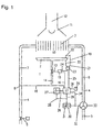
- the figure shows a schematic diagram of a gas-fired once-through water heater.
- the gas-fired instantaneous water heater 1 has one of one as the most important components atmospheric gas burner 2 heated fin heat exchanger 3, which in the course of a Waterway 4 is located, which is fed from a cold water source 5 Cold water supply line 6 and one leading away from the heat exchanger 3 Hot water tap line 7, in which a temperature sensor 8 is arranged and which of a nozzle 9 is controlled.
- the heat exchanger 3 is arranged in a combustion chamber 10 by a Exhaust collector 11 is covered, to which an exhaust pipe 12 is connected.
- the Gas burner 2 is fed from a gas line 14 provided with a solenoid valve 13, wherein the solenoid valve has an electromagnet 15 which with a line 16 with a control and regulating circuit 17 is connected. With this is also via a line 18 the temperature sensor 8 connected.
- the burner is an ignition electrode 19 and one Monitoring electrode 20 assigned. Both are connected via lines 21 and 22 to one Automatic burner controls 23 connected. This controls the line 24 Electromagnet 15 and is via a line 25 from the control / regulation circuit 17th controlled.
- This control and regulating circuit 17 is a via a line 26 Accumulator 27 assigned, which is connected via a line 28 to a further line 29 connected is. This is connected to an electric generator 30, which is connected to a rectifier 31 assigned.
- the electric generator is driven by a shaft 32 by one Vane encoder 33 in the water path 4 and more precisely in the cold water supply line 6 is arranged.
- the impeller 33 can also be used to control and Control circuit to communicate how high the actual value of the water flow is. this happens via a line 34.
- the function of the gas-fired instantaneous water heater just described is as follows: When the nozzle 9 is closed, the entire device is at rest, the accumulator 27 is either charged, freshly installed or charged from the last start-up. When the nozzle 9 is opened, a certain water throughput is set depending on the degree of opening of the nozzle or a water flow limiter or water constant flow regulator located in the course of the water path 4. This water throughput is registered by the impeller 33 and initially acts on the control and regulating circuit 17 via the line 34. At this moment, the latter is supplied with electrical energy from the charged accumulator 27 via the line 26.
- the control and regulating circuit 17 activates the automatic firing device 23 via the line 25, which activates the electromagnet 15 of the solenoid valve 13 via the line 24 and opens the solenoid valve.
- the ignition electrode 19 is supplied with high voltage via line 21, so that sparks jump from the electrode to the burner in certain time cycles, which attempt to ignite the gas-air mixture flowing out of the burner 2. After ignition has taken place, a flame forms, so that the monitoring electrode 20 notifies this via the line 22 to the automatic burner control 23, which then keeps the electromagnet 15 of the gas solenoid valve 13 open via the line 24.
- the automatic firing device 23 switches the electromagnet 15 to be de-energized via the line 24, so that the gas valve 13 closes .
- the electrical supply of the automatic burner control 23 with electrical energy follows indirectly through the accumulator 27 via the line 26 and the control and regulating circuit 17.
- the temperature controller integrated in the device consisting of the temperature sensor 8 as the actual value transmitter and the setpoint adjuster 35, which has a Line 36 is connected to the controller in the control and regulating circuit 17 and which energizes the electromagnet 15 via the line 16 is fed by the accumulator 17.
- the impeller 33 drives the electric generator 30 via the shaft 32, so that it generates alternating voltage, which is rectified in the rectifier 31 and which feeds the control and regulating circuit 17 via the line 29, and in parallel thereto via the Line 28, the accumulator 27 is charged. Accordingly, an at least partially charged accumulator is always available at the start of the device, so that the control and regulating circuit 17 can start operating immediately without a certain amount of water having to have passed the device before the electric generator 30 driven by the impeller 33 is able to supply electrical power for commissioning.
Landscapes
- Engineering & Computer Science (AREA)
- Physics & Mathematics (AREA)
- Thermal Sciences (AREA)
- Chemical & Material Sciences (AREA)
- Combustion & Propulsion (AREA)
- Mechanical Engineering (AREA)
- General Engineering & Computer Science (AREA)
- Regulation And Control Of Combustion (AREA)
- Instantaneous Water Boilers, Portable Hot-Water Supply Apparatuses, And Control Of Portable Hot-Water Supply Apparatuses (AREA)
- Control Of Eletrric Generators (AREA)
Applications Claiming Priority (4)
| Application Number | Priority Date | Filing Date | Title |
|---|---|---|---|
| DE19930248 | 1999-06-25 | ||
| DE19930248 | 1999-06-25 | ||
| DE19932265 | 1999-07-07 | ||
| DE19932265 | 1999-07-07 |
Publications (2)
| Publication Number | Publication Date |
|---|---|
| EP1063475A2 true EP1063475A2 (fr) | 2000-12-27 |
| EP1063475A3 EP1063475A3 (fr) | 2003-03-26 |
Family
ID=26054006
Family Applications (1)
| Application Number | Title | Priority Date | Filing Date |
|---|---|---|---|
| EP00111997A Ceased EP1063475A3 (fr) | 1999-06-25 | 2000-06-20 | Chauffe-eau continu à gaz |
Country Status (2)
| Country | Link |
|---|---|
| EP (1) | EP1063475A3 (fr) |
| DE (1) | DE10030132A1 (fr) |
Cited By (2)
| Publication number | Priority date | Publication date | Assignee | Title |
|---|---|---|---|---|
| EP1865272A1 (fr) * | 2006-06-09 | 2007-12-12 | Honeywell Technologies Sarl | Chauffe-eau |
| EP1688670A3 (fr) * | 2005-02-08 | 2010-09-15 | Robert Bosch Gmbh | Chauffe-eau instantané chauffé au gaz |
Families Citing this family (3)
| Publication number | Priority date | Publication date | Assignee | Title |
|---|---|---|---|---|
| DE10107190C1 (de) * | 2001-02-16 | 2002-10-10 | Heatec Thermotechnik Gmbh | Gas-Wärmeerzeugungseinrichtung |
| DE102005005679A1 (de) * | 2005-02-08 | 2006-08-10 | Robert Bosch Gmbh | Vorrichtung zur elektrischen Energieversorgung von Komponenten eines Durchlaufwassererhitzers in einem Bereitschaftsbetrieb |
| DE102009056140A1 (de) * | 2009-11-27 | 2011-06-01 | Robert Bosch Gmbh | Verfahren zum Betreiben eines Gasbrenners und Gasbrenner |
Family Cites Families (4)
| Publication number | Priority date | Publication date | Assignee | Title |
|---|---|---|---|---|
| FR1215731A (fr) * | 1958-11-07 | 1960-04-20 | Saunier Duval | Appareil de production instantanée d'eau chaude par le gaz avec allumage automatique du brûleur et dispositif de sécurité totale sans veilleuse de contrôle permanente |
| FR2583112B1 (fr) * | 1985-06-06 | 1987-08-14 | Charron Jean Claude | Microturbo-alternateur hydraulique |
| CA1323906C (fr) * | 1988-09-27 | 1993-11-02 | Ferdinand F. Hochstrasser | Raccord hydraulique pour installations sanitaires domestiques |
| DE19844856C1 (de) * | 1998-09-30 | 2000-05-18 | Honeywell Bv | Warmwasser-Heizgerät |
-
2000
- 2000-06-20 EP EP00111997A patent/EP1063475A3/fr not_active Ceased
- 2000-06-20 DE DE10030132A patent/DE10030132A1/de not_active Withdrawn
Cited By (2)
| Publication number | Priority date | Publication date | Assignee | Title |
|---|---|---|---|---|
| EP1688670A3 (fr) * | 2005-02-08 | 2010-09-15 | Robert Bosch Gmbh | Chauffe-eau instantané chauffé au gaz |
| EP1865272A1 (fr) * | 2006-06-09 | 2007-12-12 | Honeywell Technologies Sarl | Chauffe-eau |
Also Published As
| Publication number | Publication date |
|---|---|
| DE10030132A1 (de) | 2000-12-28 |
| EP1063475A3 (fr) | 2003-03-26 |
Similar Documents
| Publication | Publication Date | Title |
|---|---|---|
| EP0275439B1 (fr) | Dispositif de régulation de puissance de générateurs de chaleur à carburant | |
| DE4317981A1 (de) | Gas-Luft-Verhältnisregelvorrichtung für einen Temperaturregelkreis für Gasverbrauchseinrichtungen | |
| DE3114954A1 (de) | Regeleinrichtung fuer einen gasbefeuerten wasser- oder lufterhitzer | |
| EP0062854A1 (fr) | Dispositif de chauffage à gaz pour eau ou air | |
| EP4187163A1 (fr) | Procédé de fonctionnement d'un dispositif de chauffage | |
| EP1063475A2 (fr) | Chauffe-eau continu à gaz | |
| US4438340A (en) | Domestic electric generator and steam heating plant | |
| DE2803649A1 (de) | Heizungsanlage | |
| EP0229319B1 (fr) | Installation de chauffage à eau chaude avec calorimètre | |
| DE3310852C2 (de) | Umlaufwasserheizer | |
| EP4464950A1 (fr) | Procédé de fonctionnement d'au moins un circuit d'eau de chauffage, dispositif comprenant un circuit d'eau de chauffage et appareil de chauffage et programme informatique | |
| DE1551947B2 (de) | Einrichtung zur Steuerung der Brenner eines Dampferzeugers | |
| EP0337922A2 (fr) | Installation de chauffage | |
| EP0108032A2 (fr) | Dispositif de commande pour une source de chaleur chauffée au combustible | |
| DE10338868A1 (de) | Verfahren und Einrichtung zur Anpassung der Vorlauftemperatur eines Wärmeerzeugers an die jeweilige Heizkreisbelastung einer nachgeschalteten Heizungsanlage | |
| DE102007049478B3 (de) | Wassererhitzer | |
| DE10033910A1 (de) | Schichtenspeicher | |
| AT403423B (de) | Heizgerät, insbesondere wasserheizer, mit einer batteriegespeisten brennersteuerung mit unterspannungsmelder | |
| DE2724353C3 (de) | Warmwasserheizanlage | |
| EP0194637B1 (fr) | Circuit pour commander une source de chaleur chauffée par combustible et chargeant un réservoir à eau sanitaire | |
| EP1703224A1 (fr) | Dispositif d'alimentation électrique pour de composants d'un chauffe-eau intantané | |
| DE2609701C3 (de) | Steuereinrichtung für einen Gasbrenner | |
| DE3330374A1 (de) | Einrichtung zur steuerung des luftueberschusses an einem oelbrenner mit einem oelvorwaermer | |
| WO2026073688A1 (fr) | Appareil de commande pour four de fusion et four de fusion | |
| DE4429224A1 (de) | Gasheizgerät |
Legal Events
| Date | Code | Title | Description |
|---|---|---|---|
| PUAI | Public reference made under article 153(3) epc to a published international application that has entered the european phase |
Free format text: ORIGINAL CODE: 0009012 |
|
| AK | Designated contracting states |
Kind code of ref document: A2 Designated state(s): AT BE CH CY DE DK ES FI FR GB GR IE IT LI LU MC NL PT SE |
|
| AX | Request for extension of the european patent |
Free format text: AL;LT;LV;MK;RO;SI |
|
| RAP1 | Party data changed (applicant data changed or rights of an application transferred) |
Owner name: VAILLANT GMBH |
|
| PUAL | Search report despatched |
Free format text: ORIGINAL CODE: 0009013 |
|
| AK | Designated contracting states |
Kind code of ref document: A3 Designated state(s): AT BE CH CY DE DK ES FI FR GB GR IE IT LI LU MC NL PT SE Designated state(s): AT BE CH CY DE DK ES FI FR GB GR IE IT LI LU MC NL PT SE |
|
| AX | Request for extension of the european patent |
Extension state: AL LT LV MK RO SI |
|
| RIC1 | Information provided on ipc code assigned before grant |
Ipc: 7F 24H 9/20 B Ipc: 7F 23Q 9/08 A |
|
| 17P | Request for examination filed |
Effective date: 20030217 |
|
| AKX | Designation fees paid |
Designated state(s): AT BE CH CY DE DK ES FI FR GB GR IE IT LI LU MC NL PT SE |
|
| 17Q | First examination report despatched |
Effective date: 20040526 |
|
| 18R | Application refused |
Effective date: 20060120 |
|
| STAA | Information on the status of an ep patent application or granted ep patent |
Free format text: STATUS: THE APPLICATION HAS BEEN REFUSED |
|
| R18R | Application refused (corrected) |
Effective date: 20051021 |