EP1063496A1 - Capteur de déplacement magnétique - Google Patents
Capteur de déplacement magnétique Download PDFInfo
- Publication number
- EP1063496A1 EP1063496A1 EP00401729A EP00401729A EP1063496A1 EP 1063496 A1 EP1063496 A1 EP 1063496A1 EP 00401729 A EP00401729 A EP 00401729A EP 00401729 A EP00401729 A EP 00401729A EP 1063496 A1 EP1063496 A1 EP 1063496A1
- Authority
- EP
- European Patent Office
- Prior art keywords
- target
- transducer
- sensor according
- harmonic
- magnetic
- Prior art date
- Legal status (The legal status is an assumption and is not a legal conclusion. Google has not performed a legal analysis and makes no representation as to the accuracy of the status listed.)
- Granted
Links
- 230000005291 magnetic effect Effects 0.000 title claims abstract description 56
- 238000006073 displacement reaction Methods 0.000 title claims abstract description 25
- 230000001360 synchronised effect Effects 0.000 claims abstract description 7
- 238000004804 winding Methods 0.000 claims description 30
- 238000012545 processing Methods 0.000 claims description 10
- 238000004458 analytical method Methods 0.000 claims description 9
- 230000005294 ferromagnetic effect Effects 0.000 claims description 9
- 230000000737 periodic effect Effects 0.000 claims description 9
- 239000000463 material Substances 0.000 claims description 6
- 230000005293 ferrimagnetic effect Effects 0.000 claims description 5
- 230000005415 magnetization Effects 0.000 claims description 5
- 238000007493 shaping process Methods 0.000 claims description 3
- 230000004907 flux Effects 0.000 claims 1
- 230000008054 signal transmission Effects 0.000 claims 1
- 238000001514 detection method Methods 0.000 description 5
- 239000000696 magnetic material Substances 0.000 description 4
- 238000000354 decomposition reaction Methods 0.000 description 3
- 238000005259 measurement Methods 0.000 description 3
- 239000000523 sample Substances 0.000 description 3
- 230000035945 sensitivity Effects 0.000 description 3
- 238000004519 manufacturing process Methods 0.000 description 2
- 238000000034 method Methods 0.000 description 2
- 230000005355 Hall effect Effects 0.000 description 1
- 230000003321 amplification Effects 0.000 description 1
- KPLQYGBQNPPQGA-UHFFFAOYSA-N cobalt samarium Chemical compound [Co].[Sm] KPLQYGBQNPPQGA-UHFFFAOYSA-N 0.000 description 1
- 238000012937 correction Methods 0.000 description 1
- 230000008878 coupling Effects 0.000 description 1
- 238000010168 coupling process Methods 0.000 description 1
- 238000005859 coupling reaction Methods 0.000 description 1
- 230000007547 defect Effects 0.000 description 1
- 238000011161 development Methods 0.000 description 1
- 238000010586 diagram Methods 0.000 description 1
- 230000001939 inductive effect Effects 0.000 description 1
- UGKDIUIOSMUOAW-UHFFFAOYSA-N iron nickel Chemical compound [Fe].[Ni] UGKDIUIOSMUOAW-UHFFFAOYSA-N 0.000 description 1
- 239000006247 magnetic powder Substances 0.000 description 1
- 230000007935 neutral effect Effects 0.000 description 1
- 238000003199 nucleic acid amplification method Methods 0.000 description 1
- 210000000056 organ Anatomy 0.000 description 1
- 230000035699 permeability Effects 0.000 description 1
- 239000002994 raw material Substances 0.000 description 1
- 229910000938 samarium–cobalt magnet Inorganic materials 0.000 description 1
- 229910000859 α-Fe Inorganic materials 0.000 description 1
Images

Classifications
-
- G—PHYSICS
- G01—MEASURING; TESTING
- G01D—MEASURING NOT SPECIALLY ADAPTED FOR A SPECIFIC VARIABLE; ARRANGEMENTS FOR MEASURING TWO OR MORE VARIABLES NOT COVERED IN A SINGLE OTHER SUBCLASS; TARIFF METERING APPARATUS; MEASURING OR TESTING NOT OTHERWISE PROVIDED FOR
- G01D5/00—Mechanical means for transferring the output of a sensing member; Means for converting the output of a sensing member to another variable where the form or nature of the sensing member does not constrain the means for converting; Transducers not specially adapted for a specific variable
- G01D5/12—Mechanical means for transferring the output of a sensing member; Means for converting the output of a sensing member to another variable where the form or nature of the sensing member does not constrain the means for converting; Transducers not specially adapted for a specific variable using electric or magnetic means
- G01D5/14—Mechanical means for transferring the output of a sensing member; Means for converting the output of a sensing member to another variable where the form or nature of the sensing member does not constrain the means for converting; Transducers not specially adapted for a specific variable using electric or magnetic means influencing the magnitude of a current or voltage
- G01D5/20—Mechanical means for transferring the output of a sensing member; Means for converting the output of a sensing member to another variable where the form or nature of the sensing member does not constrain the means for converting; Transducers not specially adapted for a specific variable using electric or magnetic means influencing the magnitude of a current or voltage by varying inductance, e.g. by a movable armature
- G01D5/2006—Mechanical means for transferring the output of a sensing member; Means for converting the output of a sensing member to another variable where the form or nature of the sensing member does not constrain the means for converting; Transducers not specially adapted for a specific variable using electric or magnetic means influencing the magnitude of a current or voltage by varying inductance, e.g. by a movable armature by influencing the self-induction of one or more coils
- G01D5/2013—Mechanical means for transferring the output of a sensing member; Means for converting the output of a sensing member to another variable where the form or nature of the sensing member does not constrain the means for converting; Transducers not specially adapted for a specific variable using electric or magnetic means influencing the magnitude of a current or voltage by varying inductance, e.g. by a movable armature by influencing the self-induction of one or more coils by a movable ferromagnetic element, e.g. a core
Definitions
- the present invention relates to a displacement sensor, in particular for motor vehicle.
- the invention relates to a displacement sensor of the type comprising a magnetic target associated with a part of which there instead of picking up the displacement and a magnetic transducer connected to means for processing the output signals of this transducer, to determine the displacement of the target and therefore of the part.
- This type of sensor finds many applications for example in motor vehicles which require more and more use inexpensive position or speed sensors that should work in a harsh environment, particularly in terms of temperature and vibration.
- These sensors include a ferromagnetic core and a magnet permanent and the rotation of the target is translated by a periodic electrical signal at the output of a winding which is an image of the passage of the magnetic patterns.
- connection between the sensor and the processing means associated signals is done by a shielded cable.
- the means for processing the output signals thereof are integrated into the transducer and are therefore subject to the harsh environment.
- the object of the invention is therefore to solve these problems by proposing a simple, reliable displacement sensor that can work in a harsh environment, which has good resolution and whose cost as low as possible.
- the invention relates to a displacement sensor of the type comprising a magnetic target associated with a part which should be captured displacement and a magnetic transducer connected to processing means output signals from this transducer to determine displacement of the target and therefore of the part, characterized in that the transducer comprises at least one magnetic circuit on which is disposed at least one coil connected to means for applying a periodic radio frequency current thereto amplitude determined to generate in the magnetic circuit, a saturation field of the material thereof at each alternation of the radio-frequency current and in that the processing means include means analysis of at least one harmonic of the voltage present across the winding to determine the displacement of the target and therefore of the part.
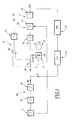
- FIG. 1 shows a displacement sensor which is designated by the general reference 1.
- This displacement sensor has a designated magnetic target by the general reference 2, associated with a part whose displacement should be captured and to a magnetic transducer designated by the general reference 3, connected to means for processing the output signals of this transducer to determine the displacement of the target and therefore of the part.
- the transducer comprises at least one magnetic circuit on which at least one winding is arranged.
- This winding is connected to means for supplying the latter with compensation current to generate a field in the magnetic circuit magnetic opposite the field created in it by the moving magnetic target in order to obtain a zero field in the circuit.
- the compensation current is designated by the reference le on this figure 1.
- the supply means are designated by the reference general 4 and are connected to the transducer winding.
- means are provided for processing the output signals. of this transducer to determine the displacement of the target and therefore of the piece, these processing means comprising means for analyzing this current compensation to determine this displacement.
- the transducer winding is also connected to means 6a for superimposing on the compensation current l c a periodic radiofrequency current l rf , for example sinusoidal, of amplitude determined to generate in the magnetic circuit, a material saturation field. of the latter at each alternation of the radiofrequency current and to means 6b for analyzing a harmonic of the resulting voltage present at the terminals of the winding to control the amplitude of the latter to zero by varying the compensation current l c .
- a periodic radiofrequency current l rf for example sinusoidal
- the harmonic analyzed can be an even harmonic such as the second or an odd harmonic such as the first.
- the superposition means designated by the general reference 6a include for example an oscillator designated by the general reference 7 on this figure 1.
- this oscillator 7 delivers a signal at a multiple frequency such as for example double that of the periodic current l rf , at the input of a frequency divider by two, designated by the general reference 8, the output of which is connected to a signal shaping module designated by the general reference 9, connected to the winding of the transducer 3.
- the analysis means 6b for their part comprise a bandpass amplifier designated by the general reference 10, which is connected to the winding of the transducer 3 to amplify and select the corresponding harmonic of the voltage signal V 1 present at the terminals thereof. ci, the output of this bandpass amplifier being connected to a multiplier 11 also receiving as input a signal from the oscillator 7, to ensure synchronous detection.
- the output of this multiplier 11 is connected to a low-pass filter 12 which delivers a voltage signal V 2h proportional to the amplitude and to the phase of the corresponding harmonic, for example a PID type corrector, designated by the general reference 13.
- This PID type corrector 13 is connected to a voltage-current converter designated by the general reference 14, delivering the compensation current l c to the winding.
- the means 5 for analyzing the compensation current l c comprise a resistor designated by the general reference 15 in this figure, in series with the winding of the transducer and at the terminals of which the inputs of an amplifier 16 are connected, the output of which is connected to a low-pass filter 17, delivering a voltage V s proportional to this compensation current.
- the bandpass amplifier 10 performs a preselection and amplification of the second harmonic, while the multiplier 11 and low pass filter 12 assembly performs the harmonic analysis by outputting a signal V 2h proportional to the amplitude and the phase of the second harmonic and at the voltage V 1 at the terminals of the winding.
- This voltage V 2h image of the second harmonic is processed by the corrector 13 for example of the PID type and the voltage-current converter 14 delivers the compensation current l c to the winding of the transducer.
- the oscillator, divider and shaping modules 7,8,9 respectively, generate the periodic current l rf at the frequency F 0 and the reference signal at the frequency 2 F0 for synchronous detection, the periodic radiofrequency resulting l rf being superimposed on the current l c delivered by the converter 14, in the winding of the transducer.
- the current flowing in this winding that is to say l rf + I C le, is taken thanks to the resistor 15 which can be a precision shunt resistor, and the amplifier 16.
- the high frequency information is eliminated by the low pass filter 17 to output a voltage signal representative of the displacement of the target.
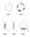
- Two main categories of magnetic targets 2 can then be used, like those illustrated in Figures 2 and 3, which respectively illustrate the production of ferromagnetic (Fig. 2) and ferrimagnetic targets (Fig. 3).
- Ferromagnetic targets are formed from magnetic material soft and have a magnetic pattern formed by teeth, lamellae magnetic or perforations, etc ...
- the ferrimagnetic targets (Fig. 3) are presented under the shape of a ring or a disc and are made of magnetic powder with high coercivity.
- FIGS. 4 to 6 various embodiments of the transducer 3.
- This transducer actually consists of a magnetic circuit on which a winding is arranged.
- the magnetic circuit is designated by the reference 20 while the winding is designated by the general reference 21.
- the magnetic circuit can then have different shapes, such as that for example the shape of a ribbon as shown in Figure 4, a wire as shown in Figure 5 or a cut torus (for example in U) as shown in Figure 6.
- All magnetic materials with high magnetic permeability, weak coercive field and weak magnetostriction can be suitable as for example materials of amorphous, nanocrystalline type, of the iron-nickel family or ferrites, etc ...
- the winding placed on this magnetic circuit and designated by the reference general 21 is a winding of N contiguous turns, uniformly distributed along the length of the magnetic circuit in one or more layers.
- the number of these turns varies for example from 50 to 300.
- the coupling of this transducer to the target can be achieved in different ways manners.
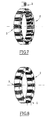
- FIGS. 7 and 8 three main positions have indeed been illustrated usable for a ferromagnetic target.
- a transverse position has indeed been illustrated in which the transducer is in the same plane as the target, but this is perpendicular to a radius of this target.
- an axial position can also be used, in which the transducer is placed in an axis perpendicular to the target plane.
- an axially magnetized target can also be used and the transducer must then be placed parallel to the axis of the target or on the slice thereof as shown in Figure 8.
- the target is ferromagnetic, made of soft magnetic material, it then add one or more magnets to the transducer, like this is illustrated.
- two magnets are added on the sides of the transducer for axial and radial positions, illustrated for example on Figures 9 and 11, while a single magnet is added in front of or behind this transducer, for the transverse position, such as that shown in the figure 10.
- magnet configurations can also work with a ferrimagnetic target.
- the axis of the magnetic circuit of the transducer 3 is placed in parallel to target 2 in the direction of easy magnetization.
- this circuit magnetized only under the influence of magnetic components applied along its axis.
- the field varies from one point to another of the magnetic circuit and its value on average, over the length of the transducer, is then positive or negative depending on the position of the transducer in the field map.
- the voltage across the transducer winding is symmetrical in the absence of internal magnetic field in the magnetic material.
- the Fourrier series decomposition leads to harmonics null peers. This same decomposition shows even harmonics non-zero in the case of the presence of an internal magnetic field.
- An even harmonic such as the second one, translates to the output of the electronic module by a continuous signal whose amplitude and sign are the image of the average magnetic field seen by the magnetic circuit.
- the zero crossing of the output signal then makes it possible to detect with very high precision, the change of sign of the radiated magnetic field by the target.
- Sensitivity is then limited only by the Earth's magnetic field or the presence of stray magnetic fields.
- Synchronous demodulation totally eliminates sensitivity to noise electromagnetic and it allows to have electronic means associated with the remote sensor thereof and to connect these two elements by via a two-wire connection for example.
- this type of sensor using decomposition harmonic of signals by synchronous demodulation is particularly suitable to the measurement of speed or movement of mechanical organs for example in motor vehicles.
- This sensor also has the advantage of being able to operate in permanence in a severe thermal environment such as beyond 200 ° C.
Landscapes
- Physics & Mathematics (AREA)
- General Physics & Mathematics (AREA)
- Measurement Of Length, Angles, Or The Like Using Electric Or Magnetic Means (AREA)
- Transmission And Conversion Of Sensor Element Output (AREA)
Abstract
Description
- la Fig.1 représente un schéma synoptique illustrant la structure générale d'un capteur de déplacement selon l'invention et des moyens électroniques associés à celui-ci;
- les Fig.2 et 3 représentent deux exemples de réalisation d'une cible magnétique entrant dans la constitution d'un capteur selon l'invention;
- les Fig.4,5 et 6 représentent trois exemples de réalisation d'un transducteur magnétique entrant dans la constitution d'un capteur selon l'invention; et
- les Fig.7 à 12 illustrent différentes dispositions relatives d'un transducteur magnétique et d'une cible magnétique.
Claims (17)
- Capteur de déplacement du type comportant une cible magnétique (2) associée à une pièce dont il y a lieu de capter le déplacement et un transducteur (3) magnétique raccordé à des moyens de traitement de signaux de sortie de ce transducteur pour déterminer le déplacement de la cible et donc de la pièce, caractérisé en ce que le transducteur (3) comporte au moins un circuit magnétique (20) sur lequel est disposé au moins un bobinage (21) raccordé à des moyens (6a) d'application à celui-ci d'un courant périodique radio-fréquence (lrf) d'amplitude déterminée pour engendrer dans le circuit magnétique, un champ de saturation du matériau de celui-ci à chaque alternance du courant radio-fréquence et en ce que les moyens de traitement comprennent des moyens d'analyse (5) d'au moins un harmonique de la tension présente aux bornes du bobinage pour en déterminer le déplacement de la cible et donc de la pièce.
- Capteur selon la revendication 1, caractérisé en ce que la cible (2) est formée par une cible ferrimagnétique.
- Capteur selon la revendication 1, caractérisé en ce que la cible (2) est formée par une cible ferromagnétique.
- Capteur selon l'une quelconque des revendications précédentes, caractérisé en ce que le transducteur (3) est disposé axialement par rapport à la cible (2).
- Capteur selon l'une quelconque des revendications 1 à 3, caractérisé en ce que le transducteur (3) est disposé radialement par rapport à la cible (2).
- Capteur selon l'une quelconque des revendications 1 à 3, caractérisé en ce que le transducteur (3) est disposé transversalement par rapport à la cible (2).
- Capteur selon l'une quelconque des revendications 1 à 3, caractérisé en ce que le transducteur (3) est disposé parallèlement à la cible (2) dans la direction de facile aimantation.
- Capteur selon l'une quelconque des revendications précédentes, caractérisé en ce qu'au moins un aimant est associé au transducteur (3) de façon à avoir un flux nul dans ce transducteur hors présence de la cible (2).
- Capteur selon l'une quelconque des revendications précédentes, caractérisé en ce que ledit harmonique est un harmonique impair.
- Capteur selon la revendication 9, caractérisé en ce que ledit harmonique est le premier harmonique.
- Capteur selon l'une quelconque des revendications 1 à 8, caractérisé en ce que ledit harmonique est un harmonique pair.
- Capteur selon la revendication 11, caractérisé en ce que ledit harmonique est le second harmonique.
- Capteur selon l'une quelconque des revendications précédentes, caractérisé en ce que les moyens d'application du courant périodique radio-fréquence comprennent un oscillateur (7) délivrant un signal à une fréquence multiple de celle du courant périodique à l'entrée d'un diviseur de fréquence (8), dont la sortie est reliée à l'entrée d'un module de mise en forme de signaux (9), dont la sortie est raccordée au bobinage et en ce que les moyens d'analyse comprennent un amplificateur passe-bande (10) dont l'entrée est raccordée au bobinage pour amplifier et sélectionner l'harmonique correspondant et dont la sortie est reliée à l'entrée d'un multiplicateur (11) recevant également en entrée le signal de sortie de l'oscillateur (7) et dont la sortie est reliée à l'entrée d'un filtre passe-bas (12) pour une analyse synchrone de signal et délivrer un signal de tension (V2h) proportionnel à l'amplitude et à la phase de l'harmonique et donc au déplacement de la cible et de la pièce.
- Capteur selon les revendications 11 ou 12 et 13, caractérisé en ce que le filtre passe-bas (12) est raccordé à des moyens d'alimentation du bobinage en courant de compensation (lc) pour engendrer dans le circuit magnétique du transducteur, un champ magnétique de compensation afin d'obtenir un champ nul dans le transducteur.
- Capteur selon la revendication 14, caractérisé en ce que les moyens d'alimentation comprennent un correcteur de type PID (13) dont la sortie est reliée à un convertisseur tension-courant (14) dont la sortie est raccordée au bobinage pour délivrer à celui-ci, le courant de compensation (lc).
- Capteur selon la revendication 15, caractérisé en ce que les moyens d'analyse comprennent une résistance (15) en série avec le bobinage, un amplificateur (16) raccordé aux bornes de cette résistance et un filtre passe-bas (17) raccordé à la sortie de l'amplificateur pour délivrer en sortie un signal de tension (Vs) proportionnel au courant de compensation et donc au déplacement de la cible et de la pièce.
- Capteur selon l'une quelconque des revendications précédentes, caractérisé en ce que le circuit magnétique et le bobinage d'une part, et les différents moyens du capteur raccordés à ceux-ci d'autre part, sont disposés à distance les uns des autres et sont raccordés par des lignes de transmission de signaux.
Applications Claiming Priority (2)
| Application Number | Priority Date | Filing Date | Title |
|---|---|---|---|
| FR9908037 | 1999-06-23 | ||
| FR9908037A FR2795503B1 (fr) | 1999-06-23 | 1999-06-23 | Capteur de deplacement comportant une cible magnetique et un transducteur magnetique, par exemple pour vehicule automobile |
Publications (2)
| Publication Number | Publication Date |
|---|---|
| EP1063496A1 true EP1063496A1 (fr) | 2000-12-27 |
| EP1063496B1 EP1063496B1 (fr) | 2004-05-06 |
Family
ID=9547221
Family Applications (1)
| Application Number | Title | Priority Date | Filing Date |
|---|---|---|---|
| EP00401729A Expired - Lifetime EP1063496B1 (fr) | 1999-06-23 | 2000-06-16 | Capteur de déplacement magnétique |
Country Status (4)
| Country | Link |
|---|---|
| EP (1) | EP1063496B1 (fr) |
| AT (1) | ATE266189T1 (fr) |
| DE (1) | DE60010374T2 (fr) |
| FR (1) | FR2795503B1 (fr) |
Cited By (1)
| Publication number | Priority date | Publication date | Assignee | Title |
|---|---|---|---|---|
| WO2010084146A1 (fr) * | 2009-01-21 | 2010-07-29 | Balluff Gmbh | Dispositif de détection conçu pour une cible dans laquelle des courants tourbillonnaires peuvent être générés, et procédé de détection |
Citations (4)
| Publication number | Priority date | Publication date | Assignee | Title |
|---|---|---|---|---|
| EP0010303A1 (fr) * | 1978-10-19 | 1980-04-30 | United Airlines, Inc. | Convertisseur de signaux |
| EP0317497A2 (fr) * | 1987-11-20 | 1989-05-24 | Vibro-Meter Sa | Détecteur de position |
| EP0466604A1 (fr) * | 1990-07-13 | 1992-01-15 | Societe D'applications Generales D'electricite Et De Mecanique Sagem | Dispositif de détermination de la position relative de deux pièces montées mobiles l'une par rapport à l'autre, et reliées par au moins un amortisseur téléscopique |
| DE4446313A1 (de) * | 1994-12-23 | 1996-06-27 | Teves Gmbh Alfred | Aktiver Sensor mit einem magnetfeldabhängigen Meßelement |
-
1999
- 1999-06-23 FR FR9908037A patent/FR2795503B1/fr not_active Expired - Fee Related
-
2000
- 2000-06-16 DE DE60010374T patent/DE60010374T2/de not_active Expired - Fee Related
- 2000-06-16 EP EP00401729A patent/EP1063496B1/fr not_active Expired - Lifetime
- 2000-06-16 AT AT00401729T patent/ATE266189T1/de not_active IP Right Cessation
Patent Citations (4)
| Publication number | Priority date | Publication date | Assignee | Title |
|---|---|---|---|---|
| EP0010303A1 (fr) * | 1978-10-19 | 1980-04-30 | United Airlines, Inc. | Convertisseur de signaux |
| EP0317497A2 (fr) * | 1987-11-20 | 1989-05-24 | Vibro-Meter Sa | Détecteur de position |
| EP0466604A1 (fr) * | 1990-07-13 | 1992-01-15 | Societe D'applications Generales D'electricite Et De Mecanique Sagem | Dispositif de détermination de la position relative de deux pièces montées mobiles l'une par rapport à l'autre, et reliées par au moins un amortisseur téléscopique |
| DE4446313A1 (de) * | 1994-12-23 | 1996-06-27 | Teves Gmbh Alfred | Aktiver Sensor mit einem magnetfeldabhängigen Meßelement |
Non-Patent Citations (1)
| Title |
|---|
| "Basic Solid-State Electronics", 1982, VAN VALKENBURGH, NOOGER & NEVILLE, INC., ROCHELLE PARK, NEW JERSEY, USA, XP002132659 * |
Cited By (3)
| Publication number | Priority date | Publication date | Assignee | Title |
|---|---|---|---|---|
| WO2010084146A1 (fr) * | 2009-01-21 | 2010-07-29 | Balluff Gmbh | Dispositif de détection conçu pour une cible dans laquelle des courants tourbillonnaires peuvent être générés, et procédé de détection |
| CN102292620A (zh) * | 2009-01-21 | 2011-12-21 | 格尔德·赖梅 | 用于感应产生电测量信号的方法和相关的传感器装置 |
| CN102292620B (zh) * | 2009-01-21 | 2013-12-25 | 格尔德·赖梅 | 用于感应产生电测量信号的方法和相关的传感器装置 |
Also Published As
| Publication number | Publication date |
|---|---|
| FR2795503B1 (fr) | 2001-09-21 |
| ATE266189T1 (de) | 2004-05-15 |
| DE60010374D1 (de) | 2004-06-09 |
| EP1063496B1 (fr) | 2004-05-06 |
| DE60010374T2 (de) | 2005-05-04 |
| FR2795503A1 (fr) | 2000-12-29 |
Similar Documents
| Publication | Publication Date | Title |
|---|---|---|
| EP0665416B1 (fr) | Capteur magnétique de position à sonde de hall | |
| EP2084496B1 (fr) | Capteur de position lineaire ou rotatif a profil d'aimant variable | |
| EP2326919B2 (fr) | Capteur de position linéaire ou rotatif à aimant permanent pour la détection d'une cible ferromagnétique | |
| FR2562253A1 (fr) | Dispositif pour capter la vitesse de rotation et/ou un angle de rotation d'un arbre | |
| FR2790549A1 (fr) | Capteur de position a sonde magneto-sensible et aimant encastre dans le fer | |
| FR2724723A1 (fr) | Capteur incremental de vitesse et/ou de position. | |
| FR3019892B1 (fr) | Dispositif de mesure pour une saisie sans contact d'un angle de rotation | |
| FR2893410A1 (fr) | Capteur de position angulaire magnetique pour une course allant jusqu'a 360 | |
| FR2952430A1 (fr) | Capteur de position magnetique bidirectionnel a rotation de champ | |
| US6657476B1 (en) | AC-coupled sensor signal conditioning circuit | |
| FR2801969A1 (fr) | Capteur analogique de decalage angulaire sans contact | |
| FR2800915A1 (fr) | Composant magnetosensible notamment element de capteur muni de systemes a couches magnetoresistantes selon un montage en pont | |
| EP1063496B1 (fr) | Capteur de déplacement magnétique | |
| FR2776064A1 (fr) | Dispositif de mesure de position angulaire utilisant un capteur magnetique | |
| FR3018113A1 (fr) | Capteur magnetique pour determiner la position relative entre une cible aimantee et un systeme de mesure | |
| JP7313932B2 (ja) | 磁気センサおよび磁気センサモジュール | |
| FR2795501A1 (fr) | Capteur de deplacement comportant une cible magnetique et un transducteur magnetique, notamment pour vehicule automobile | |
| FR2795502A1 (fr) | Capteur de deplacement comportant une cible magnetique et un transducteur magnetique, destine notamment a un vehicule automobile | |
| JP3367094B2 (ja) | 回転検出装置 | |
| EP1166295A1 (fr) | Procede pour la determination de la position d'un organe mobile dans au moins un entrefer principal d'un actionneur electromagnetique | |
| JP2009204364A (ja) | 磁性物の欠陥位置検出方法 | |
| EP1020728B1 (fr) | Dispositif de mesure d'un courant circulant dans un conducteur. | |
| JP2004271235A (ja) | 回転検出装置 | |
| EP2307897B1 (fr) | Dispositif et procédé de mesure de champ magnétique. | |
| FR2943795A1 (fr) | Dispositif pour detecteur et/ou un champ magnetique faible |
Legal Events
| Date | Code | Title | Description |
|---|---|---|---|
| PUAI | Public reference made under article 153(3) epc to a published international application that has entered the european phase |
Free format text: ORIGINAL CODE: 0009012 |
|
| AK | Designated contracting states |
Kind code of ref document: A1 Designated state(s): AT BE CH CY DE DK ES FI FR GB GR IE IT LI LU MC NL PT SE |
|
| AX | Request for extension of the european patent |
Free format text: AL;LT;LV;MK;RO;SI |
|
| 17P | Request for examination filed |
Effective date: 20001118 |
|
| AKX | Designation fees paid |
Free format text: AT BE CH CY DE DK ES FI FR GB GR IE IT LI LU MC NL PT SE |
|
| 17Q | First examination report despatched |
Effective date: 20021113 |
|
| GRAP | Despatch of communication of intention to grant a patent |
Free format text: ORIGINAL CODE: EPIDOSNIGR1 |
|
| GRAS | Grant fee paid |
Free format text: ORIGINAL CODE: EPIDOSNIGR3 |
|
| GRAA | (expected) grant |
Free format text: ORIGINAL CODE: 0009210 |
|
| AK | Designated contracting states |
Kind code of ref document: B1 Designated state(s): AT BE CH CY DE DK ES FI FR GB GR IE IT LI LU MC NL PT SE |
|
| PG25 | Lapsed in a contracting state [announced via postgrant information from national office to epo] |
Ref country code: NL Free format text: LAPSE BECAUSE OF FAILURE TO SUBMIT A TRANSLATION OF THE DESCRIPTION OR TO PAY THE FEE WITHIN THE PRESCRIBED TIME-LIMIT Effective date: 20040506 Ref country code: IE Free format text: LAPSE BECAUSE OF FAILURE TO SUBMIT A TRANSLATION OF THE DESCRIPTION OR TO PAY THE FEE WITHIN THE PRESCRIBED TIME-LIMIT Effective date: 20040506 Ref country code: FI Free format text: LAPSE BECAUSE OF FAILURE TO SUBMIT A TRANSLATION OF THE DESCRIPTION OR TO PAY THE FEE WITHIN THE PRESCRIBED TIME-LIMIT Effective date: 20040506 Ref country code: CY Free format text: LAPSE BECAUSE OF FAILURE TO SUBMIT A TRANSLATION OF THE DESCRIPTION OR TO PAY THE FEE WITHIN THE PRESCRIBED TIME-LIMIT Effective date: 20040506 Ref country code: AT Free format text: LAPSE BECAUSE OF FAILURE TO SUBMIT A TRANSLATION OF THE DESCRIPTION OR TO PAY THE FEE WITHIN THE PRESCRIBED TIME-LIMIT Effective date: 20040506 |
|
| REG | Reference to a national code |
Ref country code: GB Ref legal event code: FG4D Free format text: NOT ENGLISH |
|
| REG | Reference to a national code |
Ref country code: CH Ref legal event code: EP |
|
| PGFP | Annual fee paid to national office [announced via postgrant information from national office to epo] |
Ref country code: FR Payment date: 20040604 Year of fee payment: 5 |
|
| PGFP | Annual fee paid to national office [announced via postgrant information from national office to epo] |
Ref country code: GB Payment date: 20040608 Year of fee payment: 5 |
|
| PGFP | Annual fee paid to national office [announced via postgrant information from national office to epo] |
Ref country code: DE Payment date: 20040609 Year of fee payment: 5 |
|
| REF | Corresponds to: |
Ref document number: 60010374 Country of ref document: DE Date of ref document: 20040609 Kind code of ref document: P |
|
| PG25 | Lapsed in a contracting state [announced via postgrant information from national office to epo] |
Ref country code: LU Free format text: LAPSE BECAUSE OF NON-PAYMENT OF DUE FEES Effective date: 20040616 |
|
| REG | Reference to a national code |
Ref country code: IE Ref legal event code: FG4D Free format text: FRENCH |
|
| PG25 | Lapsed in a contracting state [announced via postgrant information from national office to epo] |
Ref country code: MC Free format text: LAPSE BECAUSE OF NON-PAYMENT OF DUE FEES Effective date: 20040630 Ref country code: LI Free format text: LAPSE BECAUSE OF NON-PAYMENT OF DUE FEES Effective date: 20040630 Ref country code: CH Free format text: LAPSE BECAUSE OF NON-PAYMENT OF DUE FEES Effective date: 20040630 Ref country code: BE Free format text: LAPSE BECAUSE OF NON-PAYMENT OF DUE FEES Effective date: 20040630 |
|
| PG25 | Lapsed in a contracting state [announced via postgrant information from national office to epo] |
Ref country code: SE Free format text: LAPSE BECAUSE OF FAILURE TO SUBMIT A TRANSLATION OF THE DESCRIPTION OR TO PAY THE FEE WITHIN THE PRESCRIBED TIME-LIMIT Effective date: 20040806 Ref country code: GR Free format text: LAPSE BECAUSE OF FAILURE TO SUBMIT A TRANSLATION OF THE DESCRIPTION OR TO PAY THE FEE WITHIN THE PRESCRIBED TIME-LIMIT Effective date: 20040806 Ref country code: DK Free format text: LAPSE BECAUSE OF FAILURE TO SUBMIT A TRANSLATION OF THE DESCRIPTION OR TO PAY THE FEE WITHIN THE PRESCRIBED TIME-LIMIT Effective date: 20040806 |
|
| PG25 | Lapsed in a contracting state [announced via postgrant information from national office to epo] |
Ref country code: ES Free format text: LAPSE BECAUSE OF FAILURE TO SUBMIT A TRANSLATION OF THE DESCRIPTION OR TO PAY THE FEE WITHIN THE PRESCRIBED TIME-LIMIT Effective date: 20040817 |
|
| GBT | Gb: translation of ep patent filed (gb section 77(6)(a)/1977) |
Effective date: 20040825 |
|
| NLV1 | Nl: lapsed or annulled due to failure to fulfill the requirements of art. 29p and 29m of the patents act | ||
| REG | Reference to a national code |
Ref country code: IE Ref legal event code: FD4D |
|
| BERE | Be: lapsed |
Owner name: PEUGEOT CITROEN AUTOMOBILES SA Effective date: 20040630 |
|
| REG | Reference to a national code |
Ref country code: CH Ref legal event code: PL |
|
| PLBE | No opposition filed within time limit |
Free format text: ORIGINAL CODE: 0009261 |
|
| STAA | Information on the status of an ep patent application or granted ep patent |
Free format text: STATUS: NO OPPOSITION FILED WITHIN TIME LIMIT |
|
| 26N | No opposition filed |
Effective date: 20050208 |
|
| PG25 | Lapsed in a contracting state [announced via postgrant information from national office to epo] |
Ref country code: IT Free format text: LAPSE BECAUSE OF NON-PAYMENT OF DUE FEES;WARNING: LAPSES OF ITALIAN PATENTS WITH EFFECTIVE DATE BEFORE 2007 MAY HAVE OCCURRED AT ANY TIME BEFORE 2007. THE CORRECT EFFECTIVE DATE MAY BE DIFFERENT FROM THE ONE RECORDED. Effective date: 20050616 Ref country code: GB Free format text: LAPSE BECAUSE OF NON-PAYMENT OF DUE FEES Effective date: 20050616 |
|
| PG25 | Lapsed in a contracting state [announced via postgrant information from national office to epo] |
Ref country code: DE Free format text: LAPSE BECAUSE OF NON-PAYMENT OF DUE FEES Effective date: 20060103 |
|
| PG25 | Lapsed in a contracting state [announced via postgrant information from national office to epo] |
Ref country code: FR Free format text: LAPSE BECAUSE OF NON-PAYMENT OF DUE FEES Effective date: 20060228 |
|
| GBPC | Gb: european patent ceased through non-payment of renewal fee |
Effective date: 20050616 |
|
| REG | Reference to a national code |
Ref country code: FR Ref legal event code: ST Effective date: 20060228 |
|
| PG25 | Lapsed in a contracting state [announced via postgrant information from national office to epo] |
Ref country code: PT Free format text: LAPSE BECAUSE OF NON-PAYMENT OF DUE FEES Effective date: 20041006 |