EP1063530A1 - Systeme de mesure de la charge résiduelle d'une batterie - Google Patents
Systeme de mesure de la charge résiduelle d'une batterie Download PDFInfo
- Publication number
- EP1063530A1 EP1063530A1 EP00113072A EP00113072A EP1063530A1 EP 1063530 A1 EP1063530 A1 EP 1063530A1 EP 00113072 A EP00113072 A EP 00113072A EP 00113072 A EP00113072 A EP 00113072A EP 1063530 A1 EP1063530 A1 EP 1063530A1
- Authority
- EP
- European Patent Office
- Prior art keywords
- voltage
- full
- residual capacity
- battery
- charge voltage
- Prior art date
- Legal status (The legal status is an assumption and is not a legal conclusion. Google has not performed a legal analysis and makes no representation as to the accuracy of the status listed.)
- Withdrawn
Links
- 238000005259 measurement Methods 0.000 title 1
- 238000001514 detection method Methods 0.000 claims description 18
- 238000012935 Averaging Methods 0.000 claims 1
- 230000007423 decrease Effects 0.000 description 10
- 238000000034 method Methods 0.000 description 7
- 230000006866 deterioration Effects 0.000 description 1
- 238000007599 discharging Methods 0.000 description 1
- 230000001172 regenerating effect Effects 0.000 description 1
- 238000005070 sampling Methods 0.000 description 1
- 230000036962 time dependent Effects 0.000 description 1
Images




Classifications
-
- G—PHYSICS
- G01—MEASURING; TESTING
- G01R—MEASURING ELECTRIC VARIABLES; MEASURING MAGNETIC VARIABLES
- G01R31/00—Arrangements for testing electric properties; Arrangements for locating electric faults; Arrangements for electrical testing characterised by what is being tested not provided for elsewhere
- G01R31/36—Arrangements for testing, measuring or monitoring the electrical condition of accumulators or electric batteries, e.g. capacity or state of charge [SoC]
- G01R31/3644—Constructional arrangements
- G01R31/3648—Constructional arrangements comprising digital calculation means, e.g. for performing an algorithm
-
- G—PHYSICS
- G01—MEASURING; TESTING
- G01R—MEASURING ELECTRIC VARIABLES; MEASURING MAGNETIC VARIABLES
- G01R31/00—Arrangements for testing electric properties; Arrangements for locating electric faults; Arrangements for electrical testing characterised by what is being tested not provided for elsewhere
- G01R31/36—Arrangements for testing, measuring or monitoring the electrical condition of accumulators or electric batteries, e.g. capacity or state of charge [SoC]
- G01R31/382—Arrangements for monitoring battery or accumulator variables, e.g. SoC
- G01R31/3842—Arrangements for monitoring battery or accumulator variables, e.g. SoC combining voltage and current measurements
-
- G—PHYSICS
- G01—MEASURING; TESTING
- G01R—MEASURING ELECTRIC VARIABLES; MEASURING MAGNETIC VARIABLES
- G01R31/00—Arrangements for testing electric properties; Arrangements for locating electric faults; Arrangements for electrical testing characterised by what is being tested not provided for elsewhere
- G01R31/005—Testing of electric installations on transport means
- G01R31/006—Testing of electric installations on transport means on road vehicles, e.g. automobiles or trucks
-
- G—PHYSICS
- G01—MEASURING; TESTING
- G01R—MEASURING ELECTRIC VARIABLES; MEASURING MAGNETIC VARIABLES
- G01R31/00—Arrangements for testing electric properties; Arrangements for locating electric faults; Arrangements for electrical testing characterised by what is being tested not provided for elsewhere
- G01R31/36—Arrangements for testing, measuring or monitoring the electrical condition of accumulators or electric batteries, e.g. capacity or state of charge [SoC]
- G01R31/3644—Constructional arrangements
- G01R31/3647—Constructional arrangements for determining the ability of a battery to perform a critical function, e.g. cranking
Definitions
- the present invention relates to a system for performing analysis, calculation, computation, determination, detection, estimation, measurement and/or prediction (hereinafter collectively referred to as "detection") of the state of charge (hereinafter sometimes abbreviated as "SOC”) of a battery, in terms of a residual capacity, by using a saturation or full-charge voltage of the battery.
- detection analysis, calculation, computation, determination, detection, estimation, measurement and/or prediction
- SOC state of charge
- a battery controller determines the residual capacity (SOC) of a battery immediately after an ignition switch is turned on, using the following expression (1), and displays this value.
- SOC [(Vn 2 -Ve 2 )]/(Vs 2 -Ve 2 )] x 100% where Vn is an estimation voltage of the battery, Ve is a discharge-end voltage of the battery, and Vs is a full-charge voltage of the battery.
- the battery is fully charged after a travel or trip, such as when in a guarage.
- the battery During operation of an electrical vehicle, the battery has its terminal voltage and discharge current providing their time-dependent values, of which prescribed numbers are collected on associated axes of a voltage vs. current coordinate system, where they are averaged to provide a set of corresponding component data.
- the regression line is determined by applying the method of least squares to calculation of the constants "a" and "b".
- a current value of the battery voltage Vn is estimated by subsituting a reference current Io into the expression of linear approximation.
- the estimation voltage Vn is substituted into the expression (1) to determine the residual capacity of the battery in terms of a current SOC during vehicle operation.
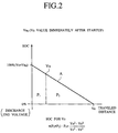
- the residual capacity is calculated to be displayed as a 100% at the startup of operation (switching of ignition to on and start of driving) after a full charge. As the vehicle is driven, the residual capacity gradually decreases along a given characteristic curve.
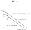
- the battery capacity becomes smaller than in a high-temperature range.
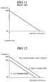
- the characteristic A would indicate a gradual decrease from a 80% residual capacity, when driving. Initially after the full charge, however, there would be a sudden decrease (a) from a 100% to lower than the 80% (for example, to a 70%), before entering the gradual decrease.
- the residual capacity at part of the characteristic curve A subsequent from the sudden decrease (a) might be by calculation based on the constant voltage Vn, thus having wrong values displayed.
- the present invention has been made with such points in view. It therefore is an object of the present invention to provide a residual capacity detection system for a battery enabling a residual battery capacity of 100% to be detected immediately after a full charge, irrespective of ambient temperatures to be high or low. It is preferable if like detection can be maintained as well during subsequent operation.
- An aspect of the present invention to achieve the object is a battery residual capacity detection system having a calculator for estimating the battery voltage from a linear approximation representing a relationship between a terminal voltage of the battery, detected by a voltage detector and a current flowing in a load from the battery, detected by a current sensor, and a reference current, and determining the residual capacity of the battery from this estimation voltage, a full-charge voltage, and a discharge-end voltage, the calculator having a full-charge voltage corrector that, immediately after a change in the load, reads the obtained estimation voltage, changes the full-charge voltage to the estimation voltage, determines the residual capacity.
- the full-charge voltage is the estimation voltage of the battery immediately after a change in the load, the subsequent residual capacity being calculated in accordance with this full-charge voltage (battery voltage estimated immediately after a change in the load).
- the residual capacity is determined using the full-charge voltage at the time of the change, resulting in a determination of the residual capacity that takes into consideration the influence of temperature.
- the present invention also has a full-charge voltage estimator. Immediately after a change occurs in the load, the full-charge voltage estimator deletes the current full-charge voltage setting, then reads the estimation voltage obtained immediately after the change and the maximum set maximum residual capacity, and using the maximum residual capacity, the estimation voltage obtained immediately after the change in the load, and the discharge-end voltage to estimate and set the new full-charge voltage.
- the estimated battery voltage immediately after the electrical vehicle motor is driven and the load changes is used to estimate the full-charge voltage corresponding to that estimation voltage, this estimated full-charge voltage being used to determine the residual capacity.
- Fig. 1 shows the general configuration of a battery residual capacity detection system according to a first embodiment of the present invention, immediately after the start of operation.
- the battery controller 1 shown in Fig. 1 discharges electrical driving power into the motor 2 (alternator) and determines the residual capacity of the battery 3 that is charged by regenerative electrical power from the motor 2.
- the battery controller 1 has a input circuit 8 connected to current sensor 6 that detects a discharge current and a full-charge current from the battery 3 and a voltage sensor that detects the voltage of the battery 3, and performs waveshaping of the detected current I and the detected voltage V, and a battery residual capacity calculator 10 (microcomputer) for sampling the current I and the voltage V form the input circuit 8 at a fixed time interval and, for collecting a plurality of averaged data when a prescribed number thereof are collected, and determining the residual capacity.
- a battery residual capacity calculator 10 microcomputer
- the battery residual capacity calculator 10 as shown in Fig. 1, has a battery voltage estimator 11, a residual capacity calculator 12, an initial capacity setter 13, and a full-charge voltage corrector 14.
- the residual capacity calculator 12 Each time the estimation voltage Vn (or Vn0) is determined by the battery voltage estimator 11, the residual capacity calculator 12 reads that estimated battery voltage Vn, a pre-established discharge-end voltage Ve, and a full-charge voltage Vs set by the full-charge voltage corrector 14, to be described later, and determines the residual capacity SOC according to the expression 1, this being stored in an SOC output register 15 and displayed.
- the initial residual capacity setter 13 writes the residual capacity after the start of operation into the output register 15, into which the residual capacity is written, as 100% residual capacity, and causes the full-charge voltage corrector 14 to start.
- the full-charge voltage corrector 14 clears the register 16, into which is stored the full-charge voltage Vs.
- the full-charge voltage is, for example, 12 V, and the residual capacity at this voltage is generally taken to be 100%.
- the estimation voltage Vn0 immediately after the ignition is switched on (or immediately after the start of running) is for example 11 V (which would be 90% with respect to the residual capacity at the reference temperature)
- the residual capacity is determined using residual capacity characteristics A, which exhibit a linear decrease, eliminating the part of the characteristics in which there is a sudden drop.
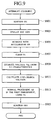
- step S301 With the switching on of the ignition (step S301), the initial residual capacity setter 13 of the residual capacity calculator 10 mounted in an electrical vehicle immediately displays the initial residual capacity SOC as 100% (step S303). That is, even if the battery full-charge voltage vary in response to the temperature (high or low), this voltage is ignored, the initial residual capacity immediately after switching the ignition on being taken as 100%.
- the battery voltage estimator 11 collects and averages a prescribed number of current I and voltage V values and, when a prescribed number of averaged data has been collected, determines the correlation coefficient r therefrom.
- step S307 the current voltage of the battery 3 immediately after start of running is estimated.
- the full-charge voltage corrector 14 sets this estimation voltage Vn0 as the full-charge voltage Vs (step S309). That is, the full-charge voltage Vs when the residual capacity SOC immediately after the ignition is switched on (or immediately after the start of running) is not made a constant value, but rather replaced by the estimation voltage Vn0.
- step S311 because the full-charge voltage Vs is the estimation voltage Vn, this is displayed as 100%, similar to step S303.
- the normal residual capacity calculation as noted above is that in which, the full-charge voltage Vs set at step S309 (this being the estimation voltage Vn0 immediately after operation startup) is taken as a fixed value in subsequent processing by the residual capacity calculator 12.
- the residual capacity calculator 12 determines the residual capacity SOC during running according to equation 2.
- steps S307 through S315 is as follows, referring to the flowchart of Fig. 4.
- the full-charge voltage corrector 14 clears the register 16 in which the full-charge voltage Vs is set (step S401).
- the full-charge voltage corrector 14 makes a judgment as to whether or not the battery voltage estimator 11 has been able to calculate the estimation voltage Vn0.
- the residual capacity calculator 12 makes a judgment as to whether the accumulated value of current I collected by the battery voltage estimator 11 corresponds to 1% of the capacity (100%) set at step S303 and, if it does correspond to 1%, the residual capacity calculator 12 subtracts from the capacity (100%) set at step S303, taking this value as the residual capacity and setting it into the register 15 (step S407), and displaying this capacity SOC on a meter (step S409).
- a reason why the estimation voltage Vn0 cannot be calculated at step S405 is that, in the case of incomplete discharging, such as immediately after the ignition is switched on, there is little change in the voltage and current, and the correlation is weak, making it impossible to calculate the estimation voltage Vn0.
- step S405 The subtraction of capacity in step S405 is also described in detail in the Japanese Patent Application Laid-Open Publication No. 9-318717.
- step S405 if the full-charge voltage corrector 14 judges that it was possible to calculate the estimation voltage Vn0, a judgment is made as to whether the full-charge voltage Vs has already been written into the register 16.
- step S413 if the judgment is made that the full-charge voltage Vs has not been calculated, the estimation voltage Vn0 calculated at step S403 is set into register 16as the full-charge voltage Vs, and a full-charge voltage set flag is set (not shown in the drawing) (step S415).
- the residual capacity calculator 12 uses equation 12 to determine the residual capacity SOC at the beginning of operation (step S417). That is, the residual capacity at the start of operation set into the register 15 at step S417 is set as the 100% data and displayed on the meter.
- the residual capacity calculator 12 uses the current estimation voltage Vn determined by the battery voltage estimator 11, the discharge-end voltage Ve, and the full-charge voltage Vs (Vn0) set into the register 16 to determine and display the residual capacity SOC, according to equation 2.
- the voltage is, for example, 10.8 V, and the residual capacity SOC is displayed as 90% (90% with respect to the residual capacity at the reference temperature). That is, there exists a point a, to which a sudden drop is made, and from this point a the residual capacity characteristics exhibit a gradually linear decrease.
- the display is 100%, and excessive charging is not done. For example, regeneratively developed current is not used for charging.
- the estimation voltage Vn0 immediately after the start of operation is taken as the full-charge voltage Vs, as shown in Fig. 7B, using residual capacity characteristics A, which exhibit a linear decrease from the full-charge voltage Vs (Vn0) as a peak, it is possible to determine the residual capacity SOC from the subsequent battery estimation voltage Vn, making it possible to accurately determine the residual capacity uninfluenced by the temperature, without using a temperature sensor.
- Fig. 8 shows the general configuration of a battery controller according to a second embodiment of the present invention.
- a battery residual capacity calculator 20 using in the battery controller of Fig. 8 has in addition to a battery voltage estimator 11, a residual capacity calculator 12, an initial capacity setter 14, and a full-charge voltage corrector 14 (not shown in the drawing) according to the first embodiment, a full-charge voltage estimator 21, and accurately calculates the residual capacity when charging is stopped midway and the residual capacity at that point is used to start running.
- the full-charge voltage estimator 21 estimates the full-charge voltage Vs from the estimation voltage Vn determined by the battery voltage estimator 11, and sets this estimated full-charge voltage Vs into the register 16.
- the initial residual capacity setter 13 of the residual capacity calculator 20 mounted in an electrical vehicle immediately displays the initial residual capacity SOC as 100% (step S903).
- the full-charge voltage estimator 21 clears the full-charge voltage Vs set in the register 16 (step S907).
- the battery voltage estimator 11 collects and averages a prescribed number of current I and voltage V values and, when a prescribed number of averaged data has been collected, determines the correlation coefficient r therefrom.
- the full-charge voltage estimator 21 of the second embodiment uses the initial residual capacity (100%) set at step S903, the estimation voltage Vn0 immediately after the start of operation determined at step S909, and a pre-established discharge-end voltage Ve to determine the full-charge voltage Vs, according to equation 3, and sets this into the register 15 (step S911).
- Vs ⁇ [((Vn-Ve)/SOC)+Ve] where Vn is the estimated battery voltage, Ve is the discharge-end voltage, and Vs is the full-charge voltage.
- the residual capacity calculator 12 uses this estimated full-charge voltage Vs to perform the normal residual capacity calculations indicated by equation 2, until the ignition is switched off.
- the capacity characteristics Bi are as shown in Fig. 10B.
- the full-charge voltage is taken as the battery voltage immediately after a change in the load, from which full-charge voltage (estimated battery voltage immediately after a change), the residual capacity immediately after the change is determined, so that immediately after a change the maximum capacity of 100% is displayed, after which with running the residual capacity gradually decreases from the maximum capacity of 100%.
- the full-charge voltage estimator estimates a full-charge voltage responsive to the estimation voltage immediately after the change, so that even if running is done on a partial charge, it is possible to obtain an full-charge voltage responsive to the estimation voltage, thereby enabling accurate detection of the residual capacity.
Landscapes
- Physics & Mathematics (AREA)
- General Physics & Mathematics (AREA)
- Secondary Cells (AREA)
- Tests Of Electric Status Of Batteries (AREA)
- Charge And Discharge Circuits For Batteries Or The Like (AREA)
Applications Claiming Priority (2)
| Application Number | Priority Date | Filing Date | Title |
|---|---|---|---|
| JP18062399 | 1999-06-25 | ||
| JP11180623A JP2001004721A (ja) | 1999-06-25 | 1999-06-25 | 満充電電圧修正機能付きバッテリの残存容量測定装置 |
Publications (1)
| Publication Number | Publication Date |
|---|---|
| EP1063530A1 true EP1063530A1 (fr) | 2000-12-27 |
Family
ID=16086457
Family Applications (1)
| Application Number | Title | Priority Date | Filing Date |
|---|---|---|---|
| EP00113072A Withdrawn EP1063530A1 (fr) | 1999-06-25 | 2000-06-26 | Systeme de mesure de la charge résiduelle d'une batterie |
Country Status (3)
| Country | Link |
|---|---|
| US (1) | US6310462B1 (fr) |
| EP (1) | EP1063530A1 (fr) |
| JP (1) | JP2001004721A (fr) |
Cited By (11)
| Publication number | Priority date | Publication date | Assignee | Title |
|---|---|---|---|---|
| WO2003106250A3 (fr) * | 2002-06-14 | 2004-07-15 | Deka Products Lp | Caracteristiques de commande pour un moyen de transport en equilibre |
| US9188984B2 (en) | 1999-06-04 | 2015-11-17 | Deka Products Limited Partnership | Control of a personal transporter based on user position |
| US9545963B2 (en) | 2002-07-12 | 2017-01-17 | DEKA Products Limited Partnership LLP | Control of a transporter based on attitude |
| US10220843B2 (en) | 2016-02-23 | 2019-03-05 | Deka Products Limited Partnership | Mobility device control system |
| USD846452S1 (en) | 2017-05-20 | 2019-04-23 | Deka Products Limited Partnership | Display housing |
| CN110249233A (zh) * | 2017-02-09 | 2019-09-17 | Abb瑞士股份有限公司 | 用于电池的健康状态估计 |
| US10802495B2 (en) | 2016-04-14 | 2020-10-13 | Deka Products Limited Partnership | User control device for a transporter |
| US10908045B2 (en) | 2016-02-23 | 2021-02-02 | Deka Products Limited Partnership | Mobility device |
| US10926756B2 (en) | 2016-02-23 | 2021-02-23 | Deka Products Limited Partnership | Mobility device |
| US11399995B2 (en) | 2016-02-23 | 2022-08-02 | Deka Products Limited Partnership | Mobility device |
| US11681293B2 (en) | 2018-06-07 | 2023-06-20 | Deka Products Limited Partnership | System and method for distributed utility service execution |
Families Citing this family (18)
| Publication number | Priority date | Publication date | Assignee | Title |
|---|---|---|---|---|
| DE10133806A1 (de) * | 2001-07-11 | 2003-01-23 | Vb Autobatterie Gmbh | Verfahren zur Bestimmung des Ladezustands von Akkumulatoren |
| JP4010288B2 (ja) | 2003-07-29 | 2007-11-21 | ソニー株式会社 | 二次電池の残容量算出方法およびバッテリパック |
| KR200422353Y1 (ko) * | 2006-05-12 | 2006-07-25 | 공만수 | 잔량이 표시되는 배터리 |
| JP4997994B2 (ja) * | 2007-01-31 | 2012-08-15 | 富士通株式会社 | 電池の残量予測装置 |
| US9397502B2 (en) | 2009-03-02 | 2016-07-19 | Volterra Semiconductor LLC | System and method for proportioned power distribution in power converter arrays |
| JP5624333B2 (ja) * | 2009-03-31 | 2014-11-12 | プライムアースEvエナジー株式会社 | 二次電池の制御装置及びマップの補正方法 |
| DE102009049589A1 (de) * | 2009-10-16 | 2011-04-21 | Bayerische Motoren Werke Aktiengesellschaft | Verfahren zur Bestimmung und/oder Vorhersage der maximalen Leistungsfähigkeit einer Batterie |
| US8854003B2 (en) | 2012-05-21 | 2014-10-07 | The United States Of America As Represented By The Secretary Of The Army | Technique for rapid battery capacity testing |
| FR3006450B1 (fr) * | 2013-06-04 | 2015-05-22 | Renault Sa | Procede pour estimer l'etat de sante d'une cellule electrochimique de stockage d'energie electrique |
| JP5852087B2 (ja) * | 2013-11-25 | 2016-02-03 | プライムアースEvエナジー株式会社 | 使用済み二次電池の選択方法、及び、組電池の製造方法 |
| TWI509270B (zh) * | 2013-11-27 | 2015-11-21 | 電池組健康狀態估測之方法與系統 | |
| CN104953193B (zh) * | 2014-03-24 | 2018-06-22 | 神讯电脑(昆山)有限公司 | 电子装置及其电池模块的监控方法 |
| JP2016099271A (ja) * | 2014-11-25 | 2016-05-30 | カルソニックカンセイ株式会社 | 二次電池の充電状態表示装置 |
| TWI541525B (zh) * | 2014-12-10 | 2016-07-11 | 大同股份有限公司 | 電池電量估測裝置及其估測方法 |
| TWI585429B (zh) * | 2015-12-31 | 2017-06-01 | 環旭電子股份有限公司 | 估計電池容量的方法 |
| CN106291390B (zh) * | 2016-10-13 | 2019-06-21 | 宁德时代新能源科技股份有限公司 | 一种电池充电时的剩余电量计算方法、装置与电池包 |
| KR102869898B1 (ko) * | 2020-09-01 | 2025-10-14 | 삼성전자주식회사 | 배터리 상태 추정 방법 및 장치 |
| CN113820605B (zh) * | 2021-09-30 | 2023-10-13 | 蜂巢能源科技(无锡)有限公司 | 电池soc的修正方法及其装置、计算机可读存储介质 |
Citations (3)
| Publication number | Priority date | Publication date | Assignee | Title |
|---|---|---|---|---|
| US5539318A (en) * | 1992-07-16 | 1996-07-23 | Toyota Jidosha Kabushiki Kaisha | Residual capacity meter for electric car battery |
| US5872453A (en) * | 1995-07-25 | 1999-02-16 | Yazaki Corporation | Battery remaining capacity measuring apparatus |
| US5898292A (en) * | 1996-05-09 | 1999-04-27 | Honda Giken Kogyo Kabushiki Kaisha | Process for evaluating remaining capacity of battery |
Family Cites Families (5)
| Publication number | Priority date | Publication date | Assignee | Title |
|---|---|---|---|---|
| JP3274287B2 (ja) | 1994-08-25 | 2002-04-15 | 矢崎総業株式会社 | 電池残存容量測定装置 |
| JPH08240647A (ja) | 1995-03-03 | 1996-09-17 | Yazaki Corp | 電池残存容量算出方法及び電池残存容量測定装置 |
| JP3164998B2 (ja) | 1995-04-07 | 2001-05-14 | 矢崎総業株式会社 | 電池残存容量測定装置 |
| JP3200364B2 (ja) | 1996-05-30 | 2001-08-20 | 矢崎総業株式会社 | 電気自動車の電池残存容量測定装置 |
| JPH1024670A (ja) | 1996-07-10 | 1998-01-27 | Canon Inc | 製本テープ及び該製本テープを使用する製本装置並びに該製本装置を備えた画像形成ライン |
-
1999
- 1999-06-25 JP JP11180623A patent/JP2001004721A/ja active Pending
-
2000
- 2000-06-26 US US09/604,059 patent/US6310462B1/en not_active Expired - Fee Related
- 2000-06-26 EP EP00113072A patent/EP1063530A1/fr not_active Withdrawn
Patent Citations (3)
| Publication number | Priority date | Publication date | Assignee | Title |
|---|---|---|---|---|
| US5539318A (en) * | 1992-07-16 | 1996-07-23 | Toyota Jidosha Kabushiki Kaisha | Residual capacity meter for electric car battery |
| US5872453A (en) * | 1995-07-25 | 1999-02-16 | Yazaki Corporation | Battery remaining capacity measuring apparatus |
| US5898292A (en) * | 1996-05-09 | 1999-04-27 | Honda Giken Kogyo Kabushiki Kaisha | Process for evaluating remaining capacity of battery |
Cited By (30)
| Publication number | Priority date | Publication date | Assignee | Title |
|---|---|---|---|---|
| US9188984B2 (en) | 1999-06-04 | 2015-11-17 | Deka Products Limited Partnership | Control of a personal transporter based on user position |
| US9411336B2 (en) | 1999-06-04 | 2016-08-09 | Deka Products Limited Partnership | Control of a personal transporter based on user position |
| US9442491B2 (en) | 1999-06-04 | 2016-09-13 | Deka Products Limited Partnership | Control of a personal transporter based on user position |
| US9442492B2 (en) | 1999-06-04 | 2016-09-13 | Deka Products Limited Partnership | Control of a personal transporter based on user position |
| WO2003106250A3 (fr) * | 2002-06-14 | 2004-07-15 | Deka Products Lp | Caracteristiques de commande pour un moyen de transport en equilibre |
| US9545963B2 (en) | 2002-07-12 | 2017-01-17 | DEKA Products Limited Partnership LLP | Control of a transporter based on attitude |
| US9400502B2 (en) | 2004-09-13 | 2016-07-26 | Deka Products Limited Partnership | Control of a personal transporter based on user position |
| US9411339B2 (en) | 2004-09-13 | 2016-08-09 | Deka Products Limited Partnership | Control of a personal transporter based on user position |
| US9429955B2 (en) | 2004-09-13 | 2016-08-30 | Deka Products Limited Partnership | Control of a personal transporter based on user position |
| US9442486B2 (en) | 2004-09-13 | 2016-09-13 | Deka Products Limited Partnership | Control of a personal transporter based on user position |
| US9459627B2 (en) | 2004-09-13 | 2016-10-04 | Deka Products Limited Partership | Control of a personal transporter based on user position |
| US9529365B2 (en) | 2004-09-13 | 2016-12-27 | Deka Products Limited Partnership | Control of a personal transporter based on user position |
| US11679044B2 (en) | 2016-02-23 | 2023-06-20 | Deka Products Limited Partnership | Mobility device |
| US12023285B2 (en) | 2016-02-23 | 2024-07-02 | Deka Products Limited Partnership | Mobility device |
| US12533971B2 (en) | 2016-02-23 | 2026-01-27 | Deka Products Limited Partnership | Mobility device control system |
| US12440401B2 (en) | 2016-02-23 | 2025-10-14 | Deka Products Limited Partnership | Mobility device |
| US10752243B2 (en) | 2016-02-23 | 2020-08-25 | Deka Products Limited Partnership | Mobility device control system |
| US12240440B2 (en) | 2016-02-23 | 2025-03-04 | Deka Products Limited Partnership | Mobility device |
| US10908045B2 (en) | 2016-02-23 | 2021-02-02 | Deka Products Limited Partnership | Mobility device |
| US10926756B2 (en) | 2016-02-23 | 2021-02-23 | Deka Products Limited Partnership | Mobility device |
| US11399995B2 (en) | 2016-02-23 | 2022-08-02 | Deka Products Limited Partnership | Mobility device |
| US10220843B2 (en) | 2016-02-23 | 2019-03-05 | Deka Products Limited Partnership | Mobility device control system |
| US11794722B2 (en) | 2016-02-23 | 2023-10-24 | Deka Products Limited Partnership | Mobility device |
| US11720115B2 (en) | 2016-04-14 | 2023-08-08 | Deka Products Limited Partnership | User control device for a transporter |
| US12117842B2 (en) | 2016-04-14 | 2024-10-15 | Deka Products Limited Partnership | User control device for a transporter |
| US10802495B2 (en) | 2016-04-14 | 2020-10-13 | Deka Products Limited Partnership | User control device for a transporter |
| CN110249233A (zh) * | 2017-02-09 | 2019-09-17 | Abb瑞士股份有限公司 | 用于电池的健康状态估计 |
| USD846452S1 (en) | 2017-05-20 | 2019-04-23 | Deka Products Limited Partnership | Display housing |
| USD876994S1 (en) | 2017-05-20 | 2020-03-03 | Deka Products Limited Partnership | Display housing |
| US11681293B2 (en) | 2018-06-07 | 2023-06-20 | Deka Products Limited Partnership | System and method for distributed utility service execution |
Also Published As
| Publication number | Publication date |
|---|---|
| US6310462B1 (en) | 2001-10-30 |
| JP2001004721A (ja) | 2001-01-12 |
Similar Documents
| Publication | Publication Date | Title |
|---|---|---|
| EP1063530A1 (fr) | Systeme de mesure de la charge résiduelle d'une batterie | |
| EP1065511B1 (fr) | Sytéme de détection de la capacité d'une batterie | |
| US10551443B2 (en) | Battery deterioration determination device, battery deterioration determination method, and vehicle | |
| JP3253495B2 (ja) | 電池残存容量測定装置 | |
| US6633165B2 (en) | In-vehicle battery monitor | |
| US7893652B2 (en) | Battery control apparatus, electric vehicle, and computer-readable medium storing a program that causes a computer to execute processing for estimating a state of charge of a secondary battery | |
| JP2004201484A (ja) | 車載バッテリ監視装置 | |
| JP5644190B2 (ja) | 電池状態推定装置および電池情報報知装置 | |
| JP3006298B2 (ja) | 電池残存容量計 | |
| JP4457781B2 (ja) | 劣化度推定方法及び劣化度推定装置 | |
| JP2003035755A (ja) | 電池蓄電量検出方法 | |
| EP3756937B1 (fr) | Appareil et procédé d'estimation de soc | |
| EP1632781A1 (fr) | Procédé et dispositif de détection de la capacité d'une batterie | |
| JP4304923B2 (ja) | 二次電池の残存容量推定装置および残存容量推定方法 | |
| JP2005274214A (ja) | 車両用バッテリの残存容量検出装置 | |
| JPH1138107A (ja) | 二次電池の残存容量推定方法 | |
| JP3634077B2 (ja) | 電池残量計 | |
| JP2002031671A (ja) | 車両のアイドリングストップ処理方法と、車両に搭載された蓄電池の残存容量測定方法、および、これらの装置 | |
| JP2004257785A (ja) | 電池状態検知システム | |
| JP2001021629A (ja) | 負荷、温度変動による容量補正機能付きバッテリの残存容量測定装置 | |
| JPH04250376A (ja) | 密閉型鉛蓄電池の残存容量推定方法 | |
| JP3930786B2 (ja) | バッテリ充電状態演算方法及びその装置 | |
| JP2007170953A (ja) | 二次電池の劣化判定装置 | |
| JP4442262B2 (ja) | 電池状態検出装置 | |
| KR20200102891A (ko) | 배터리 관리 시스템, 배터리 관리 방법 및 배터리 팩 |
Legal Events
| Date | Code | Title | Description |
|---|---|---|---|
| PUAI | Public reference made under article 153(3) epc to a published international application that has entered the european phase |
Free format text: ORIGINAL CODE: 0009012 |
|
| 17P | Request for examination filed |
Effective date: 20000626 |
|
| AK | Designated contracting states |
Kind code of ref document: A1 Designated state(s): DE FR GB IT SE |
|
| AX | Request for extension of the european patent |
Free format text: AL;LT;LV;MK;RO;SI |
|
| AKX | Designation fees paid |
Free format text: DE FR GB IT SE |
|
| STAA | Information on the status of an ep patent application or granted ep patent |
Free format text: STATUS: THE APPLICATION IS DEEMED TO BE WITHDRAWN |
|
| 18D | Application deemed to be withdrawn |
Effective date: 20050103 |