EP1063642A2 - Support d'enregistrement optique - Google Patents
Support d'enregistrement optique Download PDFInfo
- Publication number
- EP1063642A2 EP1063642A2 EP00112386A EP00112386A EP1063642A2 EP 1063642 A2 EP1063642 A2 EP 1063642A2 EP 00112386 A EP00112386 A EP 00112386A EP 00112386 A EP00112386 A EP 00112386A EP 1063642 A2 EP1063642 A2 EP 1063642A2
- Authority
- EP
- European Patent Office
- Prior art keywords
- prepit
- area
- width
- push
- groove
- Prior art date
- Legal status (The legal status is an assumption and is not a legal conclusion. Google has not performed a legal analysis and makes no representation as to the accuracy of the status listed.)
- Granted
Links
Images
Classifications
-
- G—PHYSICS
- G11—INFORMATION STORAGE
- G11B—INFORMATION STORAGE BASED ON RELATIVE MOVEMENT BETWEEN RECORD CARRIER AND TRANSDUCER
- G11B7/00—Recording or reproducing by optical means, e.g. recording using a thermal beam of optical radiation by modifying optical properties or the physical structure, reproducing using an optical beam at lower power by sensing optical properties; Record carriers therefor
- G11B7/24—Record carriers characterised by shape, structure or physical properties, or by the selection of the material
- G11B7/2407—Tracks or pits; Shape, structure or physical properties thereof
- G11B7/24073—Tracks
- G11B7/24079—Width or depth
-
- G—PHYSICS
- G11—INFORMATION STORAGE
- G11B—INFORMATION STORAGE BASED ON RELATIVE MOVEMENT BETWEEN RECORD CARRIER AND TRANSDUCER
- G11B7/00—Recording or reproducing by optical means, e.g. recording using a thermal beam of optical radiation by modifying optical properties or the physical structure, reproducing using an optical beam at lower power by sensing optical properties; Record carriers therefor
- G11B7/24—Record carriers characterised by shape, structure or physical properties, or by the selection of the material
- G11B7/2407—Tracks or pits; Shape, structure or physical properties thereof
- G11B7/24085—Pits
-
- G—PHYSICS
- G11—INFORMATION STORAGE
- G11B—INFORMATION STORAGE BASED ON RELATIVE MOVEMENT BETWEEN RECORD CARRIER AND TRANSDUCER
- G11B7/00—Recording or reproducing by optical means, e.g. recording using a thermal beam of optical radiation by modifying optical properties or the physical structure, reproducing using an optical beam at lower power by sensing optical properties; Record carriers therefor
- G11B7/007—Arrangement of the information on the record carrier, e.g. form of tracks, actual track shape, e.g. wobbled, or cross-section, e.g. v-shaped; Sequential information structures, e.g. sectoring or header formats within a track
- G11B7/00718—Groove and land recording, i.e. user data recorded both in the grooves and on the lands
-
- G—PHYSICS
- G11—INFORMATION STORAGE
- G11B—INFORMATION STORAGE BASED ON RELATIVE MOVEMENT BETWEEN RECORD CARRIER AND TRANSDUCER
- G11B7/00—Recording or reproducing by optical means, e.g. recording using a thermal beam of optical radiation by modifying optical properties or the physical structure, reproducing using an optical beam at lower power by sensing optical properties; Record carriers therefor
- G11B7/007—Arrangement of the information on the record carrier, e.g. form of tracks, actual track shape, e.g. wobbled, or cross-section, e.g. v-shaped; Sequential information structures, e.g. sectoring or header formats within a track
- G11B7/00745—Sectoring or header formats within a track
Definitions
- the present invention relates to recordable (once-writable) and rewritable information-recording media, and more particularly, to optical discs.
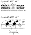
- Figs. 5A and 5B show a disc of related art, and are a top view and a perspective view of the disc, respectively.
- Fig. 5B a cross section of the disc is also shown.
- Reference symbols 'G' and 'L' indicate a groove and a land, respectively.
- Reference symbol 'PP' indicates a prepit.
- Light 3 (typically, a laser beam) is condensed by a lens 2 and then incident through a substrate 1. Comparing the land with the groove, the groove is nearer to the lens 2.
- a recording layer of a material represented by a magneto-optical material, a phase-change material or an organic dye material is formed (not shown in the figures) on the lands, grooves, and prepits.
- a recording mark M is written in the groove. This is because better signals in quality are obtained when the information is written in the grooves than when written on the lands.
- tracking servo control is implemented by a push-pull method using a servo control signal called the 'push-pull signal' resulting from the diffraction of light at the grooves and prepits.
- a light beam ('beam spot') condensed by the lens 2 tracks on the grooves and prepits.
- the push-pull signal in the prepit area has a smaller amplitude than the push-pull signal in the groove area.
- the reason for that is as follows.
- the structure of the prepit area in which concave portions are spaced from each other is equivalent to the structure of a broken, or discontinuous groove. Therefore, in the prepit area, due to the discontinuity of the concave portions, the amount of diffraction of light is reduced accordingly on the average. This is why that the amplitude of the push-pull signal is smaller in the prepit area than in the groove area.
- the gain of the tracking servo control is adjusted so that it is suitable for the groove area, the amplitude of the push-pull signal in the prepit area becomes too small. Therefore, the gain of the tracking servo control is relatively small for the prepit area, and the control precision deteriorates. In contrast, if the gain of the tracking servo control is adapted to the prepit area, the amplitude of the push-pull signal in the groove area becomes excessively large. Thus, disadvantageously, oscillation occurs in the tracking servo system.
- the present invention has been made in order to solve the above problems, and the object of the present invention is to provide a highly reliable optical recording medium with a prepit area wherein recording is implemented at least at grooves, and push-pull signals obtained in a groove area (recording area) and a prepit area have similar magnitudes so that precise tracking can be implemented without deterioration of control precision nor occurrence of oscillation of the tracking servo control system, whereby complication of the circuitry of a recording/reproducing device and the increase of the costs of such a device can be avoided.
- an optical recording medium comprising a substrate having a recording area, composed at least of lands and grooves, and a prepit area in which information has been recorded beforehand in the form of prepits, the recording area being recordable at least at the grooves among the lands and grooves,
- the amplitudes of the push-pull signals from the recording area (groove area) and the prepit area can be made equivalent to each other or little different from each other.
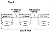
- an optical recording medium comprising a substrate having a recording area, composed at least of lands and grooves, and a prepit area in which information has been recorded beforehand in the form of prepits, the recording area being recordable at least at the grooves among the lands and grooves, wherein a sum of lengths of pit-presence portions in the prepit area is larger than a sum of lengths of pit-absence portions in the prepit area.
- the inventor of this invention has found that by increasing duty of prepits (also referred to as simply 'pits') which is calculated from (the sum of lengths of the pit-presence portions in the prepit area)/(the sum of lengths of the pit-presence portions and pit-absence portions in the prepit area), it is possible to increase the amplitude of the push-pull signal from the prepit area.
- the optical recording medium with this arrangement has duty of prepits of more than 50 %.
- first and second aspects of the present invention may be combined so that not only the widths of the grooves and prepits but also the duty of prepits are changed.
- freedom is increased in designing the optical recording medium such that there is no difference or little difference between the amplitudes of the push-pull signals from the groove area and the prepit area.
- the grooves G and prepits PP each have a depth of 30 nm.
- GeSbTe which is a phase-change material, was used for the recording layer.
- Each disc was rotated at a linear velocity of 3.5 m/s for recording and reproducing.
- Embodiment 1 is described below with reference to Figs. 1 and 2.
- Discs having different groove widths, Wg, land widths, Wl, and prepit widths, Wp, were first prepared, with their groove depths and prepit depths fixed to the above-mentioned values, respectively. Then, a test of these discs was carried out to measure the amplitudes of the push-pull signals from the groove area (namely, recording area) and the prepit area.
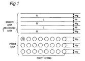
- Fig. 1 is an explanatory illustration showing a part of an optical disc prepared.
- the groove area includes alternate grooves G and lands L, and the prepit area includes strings of prepits PP (referred to also as simply 'pits').
- the grooves/lands define concentric circles or a helix together with the prepit strings, although not shown in the figures.
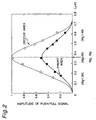
- Fig. 2 is a graph showing the measurement results.
- the axis of abscissas indicates the groove width, Wg, and the prepit width, Wp
- the axis of ordinates indicates the amplitude of the push-pull signal for Wg and Wp.
- the prepit width, Wp is equal to or larger than the sum of Wg and Wl (a track pitch: 0.74 ⁇ m in this example). This is because if so, the adjacent prepit strings will touch or overlap each other.
- the push-pull signal of the groove area has an amplitude of 0.5 after normalized.
- Wg, Wp, and Wl that allow the push-pull signals from the groove area and the prepit area to have almost equal amplitudes, or slightly different amplitudes.
- Such combinations exist under the following formularized conditions: Wl > Wg, and Wp > Wg, or alternatively, Wl ⁇ Wg, and Wp ⁇ Wg
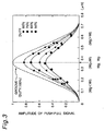
- Various optical discs were prepared by changing the duty of the prepit area while maintaining the prepit width, Wp, at a constant value (0.37 ⁇ m). Then, amplitudes of push-pull signals of the optical discs were measured. Fig. 3 shows the measurement results.
- the 'duty' here means a rate of occupation of pit-presence portions in the prepit area, and is calculated from (the total length of the pit-presence portions)/(the sum of the total length of the pit-presence portions and the total length of the pit-absence portions).
- the larger the duty the larger the push-pull signal.
- the duty of 100 % of the prepit area represents the state in which pits are not separated from each other, or rather a single pit extends continuously. In other words, the prepit area having the duty of 100 % is equivalent to the groove, and this value of the duty allows a push-pull signal to have the largest amplitude.
- the prepit width, Wp is 0.37 ⁇ m (the track pitch is 0.74 ⁇ m as in Embodiment.). Even if the prepit width, Wp, is changed from this value, there remains the inclination that the larger duty provides the larger amplitude of the push-pull signal, although the maximum value of the amplitude depends on the prepit width.
- the axis of ordinates of the graph in Fig. 3 indicates normalized values of amplitudes of the individual push-pull signal derived from various duties at the given prepit width, Wp, (0.37 ⁇ m in this case), wherein normalization has been done using, as a value of 1, the amplitude of the push-pull signal derived from the duty of 100 %.
- Embodiment 1 description has been made of a technique of making the groove width, Wg, and the prepit width, Wp, different from each other to obtain push-pull signals of almost same amplitudes in both the groove area and the prepit area.
- the prepit width, Wp can be the same as the groove width, Wg. Therefore, the optical discs (optical recording media) of the present embodiment can be simply fabricated.
- the pit width may be, of course, designed to be different from the groove width, as in Embodiment 1.
- parameters for balancing the amplitude of the push-pull signal in the groove area with that of the push-pull signal in the prepit area include not only the pit width and the groove width, but also the duty of pits. As a result, freedom of design increases, as compared with the technique of Embodiment 1.
- the above discussion holds true for the push-pull signal derived from between the prepit strings because the push-pull signal derived from between the prepit strings has the same amplitude as that of the push-pull signal derived from the prepit string, although the phase of the signal is reversed.
- an optical system having a wavelength of 650 nm and a numerical aperture (NA) of 0.6 is used. It is evident, however, that the effects of the present invention are not limited by the optical system. Furthermore, the track pitch, the groove width and the prepit width are not limited to the values shown above. Needless to say, following the gist of the present invention, it is possible to arrange various combinations of widths within the range as set forth in claims.
Landscapes
- Optical Record Carriers And Manufacture Thereof (AREA)
- Optical Recording Or Reproduction (AREA)
Applications Claiming Priority (2)
| Application Number | Priority Date | Filing Date | Title |
|---|---|---|---|
| JP11174915A JP2001006220A (ja) | 1999-06-22 | 1999-06-22 | 光記録媒体 |
| JP17491599 | 1999-06-22 |
Publications (3)
| Publication Number | Publication Date |
|---|---|
| EP1063642A2 true EP1063642A2 (fr) | 2000-12-27 |
| EP1063642A3 EP1063642A3 (fr) | 2004-03-31 |
| EP1063642B1 EP1063642B1 (fr) | 2008-01-23 |
Family
ID=15986941
Family Applications (1)
| Application Number | Title | Priority Date | Filing Date |
|---|---|---|---|
| EP00112386A Expired - Lifetime EP1063642B1 (fr) | 1999-06-22 | 2000-06-09 | Support d'enregistrement optique |
Country Status (5)
| Country | Link |
|---|---|
| US (1) | US6487165B1 (fr) |
| EP (1) | EP1063642B1 (fr) |
| JP (1) | JP2001006220A (fr) |
| KR (1) | KR100386040B1 (fr) |
| DE (1) | DE60037851T2 (fr) |
Cited By (1)
| Publication number | Priority date | Publication date | Assignee | Title |
|---|---|---|---|---|
| US7016295B2 (en) * | 2000-04-26 | 2006-03-21 | Optical Disc Corporation | Hybrid discs displaying certain dimensional values |
Families Citing this family (1)
| Publication number | Priority date | Publication date | Assignee | Title |
|---|---|---|---|---|
| JP4206620B2 (ja) * | 2000-07-31 | 2009-01-14 | 日本ビクター株式会社 | 光情報記録媒体およびその記録再生装置 |
Family Cites Families (14)
| Publication number | Priority date | Publication date | Assignee | Title |
|---|---|---|---|---|
| US5107486A (en) * | 1985-12-04 | 1992-04-21 | Sharp Kabushiki Kaisha | Optical memory device with grooves and pits in selected dimensional relationship |
| DE3876544T3 (de) * | 1987-09-02 | 1999-04-29 | Sharp K.K., Osaka | Optisches Speichersystem. |
| US5204852A (en) * | 1990-02-17 | 1993-04-20 | Victor Company Of Japan, Ltd. | Optical disc-like recoding medium and manufacturing method thereof |
| JP2755355B2 (ja) * | 1990-03-15 | 1998-05-20 | 松下電器産業株式会社 | 情報記録媒体 |
| JPH05120733A (ja) | 1991-10-24 | 1993-05-18 | Hitachi Ltd | 光デイスク |
| US5638354A (en) * | 1993-07-16 | 1997-06-10 | Ricoh Company, Ltd. | Optical information recording medium |
| US5581539A (en) * | 1994-08-12 | 1996-12-03 | Mitsubishi Chemical Corporation | Optical recording medium |
| JP2788022B2 (ja) * | 1995-02-14 | 1998-08-20 | 株式会社日立製作所 | 光記録媒体 |
| US5982738A (en) * | 1995-02-14 | 1999-11-09 | Hitachi, Ltd. | Optical recording medium having at least wobbled synchronous information shared between tracks |
| JPH08293129A (ja) * | 1995-04-21 | 1996-11-05 | Matsushita Electric Ind Co Ltd | 光学的情報記録媒体 |
| US6118752A (en) * | 1995-07-07 | 2000-09-12 | Matsushita Electric Industrial Co., Ltd. | Optical information recording medium offset pre-pit array indicating identification information |
| JP3065529B2 (ja) | 1996-03-12 | 2000-07-17 | 株式会社リコー | 光情報記録媒体および光情報記録媒体のトラッキングサーボ方法 |
| JPH09306034A (ja) * | 1996-05-20 | 1997-11-28 | Sony Corp | 光学式記録媒体 |
| JPH11126372A (ja) * | 1997-10-23 | 1999-05-11 | Pioneer Electron Corp | 光記録媒体 |
-
1999
- 1999-06-22 JP JP11174915A patent/JP2001006220A/ja active Pending
-
2000
- 2000-06-09 EP EP00112386A patent/EP1063642B1/fr not_active Expired - Lifetime
- 2000-06-09 DE DE60037851T patent/DE60037851T2/de not_active Expired - Lifetime
- 2000-06-19 US US09/596,483 patent/US6487165B1/en not_active Expired - Lifetime
- 2000-06-21 KR KR10-2000-0034085A patent/KR100386040B1/ko not_active Expired - Fee Related
Cited By (1)
| Publication number | Priority date | Publication date | Assignee | Title |
|---|---|---|---|---|
| US7016295B2 (en) * | 2000-04-26 | 2006-03-21 | Optical Disc Corporation | Hybrid discs displaying certain dimensional values |
Also Published As
| Publication number | Publication date |
|---|---|
| DE60037851T2 (de) | 2009-01-22 |
| US6487165B1 (en) | 2002-11-26 |
| KR100386040B1 (ko) | 2003-06-02 |
| EP1063642B1 (fr) | 2008-01-23 |
| JP2001006220A (ja) | 2001-01-12 |
| DE60037851D1 (de) | 2008-03-13 |
| KR20010007463A (ko) | 2001-01-26 |
| EP1063642A3 (fr) | 2004-03-31 |
Similar Documents
| Publication | Publication Date | Title |
|---|---|---|
| US6438098B1 (en) | Optical recording medium, media tracking method and recording/reproducing apparatus | |
| JP3268126B2 (ja) | 光記録媒体 | |
| US6532208B2 (en) | Optical recording medium having prepits deeper than grooves | |
| EP1341167B1 (fr) | Support d'enregistrement optique et dispositif de disques optiques | |
| US6549511B1 (en) | Optical disk medium having features for radial tilt detection and apparatus for measuring radial tilt | |
| EP0898270A2 (fr) | Disque optique et procédé d'enregistrement et de lecture associé | |
| KR20000061315A (ko) | 광디스크 기판 | |
| US6487165B1 (en) | Optical recording medium | |
| JPH09237441A (ja) | 光ディスク及びその記録再生方法 | |
| JPS6151631A (ja) | 光磁気メモリ素子 | |
| JP2644840B2 (ja) | 光ディスク | |
| US20020127365A1 (en) | Optical recording medium | |
| JPH1092016A (ja) | 光ディスク | |
| EP1262964A1 (fr) | Disque optique | |
| CN1327419C (zh) | 磁光记录介质 | |
| JPH09251674A (ja) | 光ディスク及びその記録再生方法 | |
| JPH0917032A (ja) | 光情報記録媒体 | |
| JPH07105569A (ja) | 光学的情報記録部材 | |
| JPH09231615A (ja) | 光ディスク及びその記録方法 | |
| JPH1027384A (ja) | 光ディスク | |
| JPH10188378A (ja) | 光磁気記録媒体及びその記録再生方法 | |
| JPH05298705A (ja) | 光記録再生装置 | |
| JPH09282715A (ja) | 光ディスク | |
| JPH08306079A (ja) | 光記録媒体 | |
| JPH0917031A (ja) | 光ディスク |
Legal Events
| Date | Code | Title | Description |
|---|---|---|---|
| PUAI | Public reference made under article 153(3) epc to a published international application that has entered the european phase |
Free format text: ORIGINAL CODE: 0009012 |
|
| AK | Designated contracting states |
Kind code of ref document: A2 Designated state(s): AT BE CH CY DE DK ES FI FR GB GR IE IT LI LU MC NL PT SE |
|
| AX | Request for extension of the european patent |
Free format text: AL;LT;LV;MK;RO;SI |
|
| PUAL | Search report despatched |
Free format text: ORIGINAL CODE: 0009013 |
|
| AK | Designated contracting states |
Kind code of ref document: A3 Designated state(s): AT BE CH CY DE DK ES FI FR GB GR IE IT LI LU MC NL PT SE |
|
| AX | Request for extension of the european patent |
Extension state: AL LT LV MK RO SI |
|
| RIC1 | Information provided on ipc code assigned before grant |
Ipc: 7G 11B 7/007 A Ipc: 7G 11B 7/09 B Ipc: 7G 11B 7/013 B |
|
| 17P | Request for examination filed |
Effective date: 20040827 |
|
| AKX | Designation fees paid |
Designated state(s): DE FR GB |
|
| 17Q | First examination report despatched |
Effective date: 20050221 |
|
| GRAP | Despatch of communication of intention to grant a patent |
Free format text: ORIGINAL CODE: EPIDOSNIGR1 |
|
| GRAS | Grant fee paid |
Free format text: ORIGINAL CODE: EPIDOSNIGR3 |
|
| GRAA | (expected) grant |
Free format text: ORIGINAL CODE: 0009210 |
|
| AK | Designated contracting states |
Kind code of ref document: B1 Designated state(s): DE FR GB |
|
| REG | Reference to a national code |
Ref country code: GB Ref legal event code: FG4D |
|
| REF | Corresponds to: |
Ref document number: 60037851 Country of ref document: DE Date of ref document: 20080313 Kind code of ref document: P |
|
| ET | Fr: translation filed | ||
| PLBE | No opposition filed within time limit |
Free format text: ORIGINAL CODE: 0009261 |
|
| STAA | Information on the status of an ep patent application or granted ep patent |
Free format text: STATUS: NO OPPOSITION FILED WITHIN TIME LIMIT |
|
| 26N | No opposition filed |
Effective date: 20081024 |
|
| PGFP | Annual fee paid to national office [announced via postgrant information from national office to epo] |
Ref country code: GB Payment date: 20140604 Year of fee payment: 15 |
|
| PGFP | Annual fee paid to national office [announced via postgrant information from national office to epo] |
Ref country code: DE Payment date: 20140603 Year of fee payment: 15 |
|
| PGFP | Annual fee paid to national office [announced via postgrant information from national office to epo] |
Ref country code: FR Payment date: 20140609 Year of fee payment: 15 |
|
| REG | Reference to a national code |
Ref country code: DE Ref legal event code: R119 Ref document number: 60037851 Country of ref document: DE |
|
| GBPC | Gb: european patent ceased through non-payment of renewal fee |
Effective date: 20150609 |
|
| REG | Reference to a national code |
Ref country code: FR Ref legal event code: ST Effective date: 20160229 |
|
| PG25 | Lapsed in a contracting state [announced via postgrant information from national office to epo] |
Ref country code: GB Free format text: LAPSE BECAUSE OF NON-PAYMENT OF DUE FEES Effective date: 20150609 Ref country code: DE Free format text: LAPSE BECAUSE OF NON-PAYMENT OF DUE FEES Effective date: 20160101 |
|
| PG25 | Lapsed in a contracting state [announced via postgrant information from national office to epo] |
Ref country code: FR Free format text: LAPSE BECAUSE OF NON-PAYMENT OF DUE FEES Effective date: 20150630 |