EP1063658A2 - Circuit magnétique - Google Patents
Circuit magnétique Download PDFInfo
- Publication number
- EP1063658A2 EP1063658A2 EP00113442A EP00113442A EP1063658A2 EP 1063658 A2 EP1063658 A2 EP 1063658A2 EP 00113442 A EP00113442 A EP 00113442A EP 00113442 A EP00113442 A EP 00113442A EP 1063658 A2 EP1063658 A2 EP 1063658A2
- Authority
- EP
- European Patent Office
- Prior art keywords
- magnetic
- pole magnet
- magnet
- magnets
- pole
- Prior art date
- Legal status (The legal status is an assumption and is not a legal conclusion. Google has not performed a legal analysis and makes no representation as to the accuracy of the status listed.)
- Granted
Links
- 230000005291 magnetic effect Effects 0.000 title claims abstract description 137
- 230000005405 multipole Effects 0.000 claims abstract description 27
- 125000006850 spacer group Chemical group 0.000 claims description 4
- 230000004907 flux Effects 0.000 description 30
- 238000009826 distribution Methods 0.000 description 19
- 238000013016 damping Methods 0.000 description 8
- 230000005415 magnetization Effects 0.000 description 4
- 238000012986 modification Methods 0.000 description 4
- 230000004048 modification Effects 0.000 description 4
- 239000010949 copper Substances 0.000 description 3
- 239000000463 material Substances 0.000 description 3
- 230000002829 reductive effect Effects 0.000 description 3
- 238000010276 construction Methods 0.000 description 2
- 229910052802 copper Inorganic materials 0.000 description 2
- 230000005292 diamagnetic effect Effects 0.000 description 2
- 230000005674 electromagnetic induction Effects 0.000 description 2
- 238000002955 isolation Methods 0.000 description 2
- 229910052751 metal Inorganic materials 0.000 description 2
- 239000002184 metal Substances 0.000 description 2
- 229910052761 rare earth metal Inorganic materials 0.000 description 2
- 150000002910 rare earth metals Chemical class 0.000 description 2
- 230000002441 reversible effect Effects 0.000 description 2
- 230000002269 spontaneous effect Effects 0.000 description 2
- 230000003068 static effect Effects 0.000 description 2
- 239000000725 suspension Substances 0.000 description 2
- RYGMFSIKBFXOCR-UHFFFAOYSA-N Copper Chemical compound [Cu] RYGMFSIKBFXOCR-UHFFFAOYSA-N 0.000 description 1
- CBENFWSGALASAD-UHFFFAOYSA-N Ozone Chemical compound [O-][O+]=O CBENFWSGALASAD-UHFFFAOYSA-N 0.000 description 1
- 229910052782 aluminium Inorganic materials 0.000 description 1
- XAGFODPZIPBFFR-UHFFFAOYSA-N aluminium Chemical compound [Al] XAGFODPZIPBFFR-UHFFFAOYSA-N 0.000 description 1
- 230000002238 attenuated effect Effects 0.000 description 1
- 230000005347 demagnetization Effects 0.000 description 1
- 230000006866 deterioration Effects 0.000 description 1
- 230000000694 effects Effects 0.000 description 1
- 230000005484 gravity Effects 0.000 description 1
- 238000005339 levitation Methods 0.000 description 1
- 230000005381 magnetic domain Effects 0.000 description 1
- 239000011553 magnetic fluid Substances 0.000 description 1
- 238000000034 method Methods 0.000 description 1
- 229910001172 neodymium magnet Inorganic materials 0.000 description 1
- 239000003921 oil Substances 0.000 description 1
- 230000000737 periodic effect Effects 0.000 description 1
- 230000010287 polarization Effects 0.000 description 1
- 230000035807 sensation Effects 0.000 description 1
- 230000035939 shock Effects 0.000 description 1
- 239000003190 viscoelastic substance Substances 0.000 description 1
- 230000003313 weakening effect Effects 0.000 description 1
Images


Classifications
-
- H—ELECTRICITY
- H01—ELECTRIC ELEMENTS
- H01F—MAGNETS; INDUCTANCES; TRANSFORMERS; SELECTION OF MATERIALS FOR THEIR MAGNETIC PROPERTIES
- H01F3/00—Cores, Yokes, or armatures
- H01F3/10—Composite arrangements of magnetic circuits
-
- F—MECHANICAL ENGINEERING; LIGHTING; HEATING; WEAPONS; BLASTING
- F16—ENGINEERING ELEMENTS AND UNITS; GENERAL MEASURES FOR PRODUCING AND MAINTAINING EFFECTIVE FUNCTIONING OF MACHINES OR INSTALLATIONS; THERMAL INSULATION IN GENERAL
- F16F—SPRINGS; SHOCK-ABSORBERS; MEANS FOR DAMPING VIBRATION
- F16F6/00—Magnetic springs; Fluid magnetic springs, i.e. magnetic spring combined with a fluid
- F16F6/005—Magnetic springs; Fluid magnetic springs, i.e. magnetic spring combined with a fluid using permanent magnets only
-
- H—ELECTRICITY
- H01—ELECTRIC ELEMENTS
- H01F—MAGNETS; INDUCTANCES; TRANSFORMERS; SELECTION OF MATERIALS FOR THEIR MAGNETIC PROPERTIES
- H01F7/00—Magnets
- H01F7/02—Permanent magnets [PM]
- H01F7/0231—Magnetic circuits with PM for power or force generation
- H01F7/0236—Magnetic suspension or levitation
-
- F—MECHANICAL ENGINEERING; LIGHTING; HEATING; WEAPONS; BLASTING
- F16—ENGINEERING ELEMENTS AND UNITS; GENERAL MEASURES FOR PRODUCING AND MAINTAINING EFFECTIVE FUNCTIONING OF MACHINES OR INSTALLATIONS; THERMAL INSULATION IN GENERAL
- F16C—SHAFTS; FLEXIBLE SHAFTS; ELEMENTS OR CRANKSHAFT MECHANISMS; ROTARY BODIES OTHER THAN GEARING ELEMENTS; BEARINGS
- F16C32/00—Bearings not otherwise provided for
- F16C32/04—Bearings not otherwise provided for using magnetic or electric supporting means
- F16C32/0406—Magnetic bearings
- F16C32/0408—Passive magnetic bearings
- F16C32/0423—Passive magnetic bearings with permanent magnets on both parts repelling each other
Definitions
- the present invention relates to a magnetic circuit that constitutes a repulsive magneto-spring and As mounted on a suspension unit or the like.
- springs and damping materials such as metal springs, rubber, air springs, viscoelastic materials, and dampers
- dampers are combined to optimize vibration isolating properties.
- this combination often exhibits opposing characteristics, as in the relationship between the dynamic magnification and the loss factor.
- many studies are being conducted on controlling vibration using passive vibration isolators including dynamic dampers, or quasi-active or active control systems.
- the dampers which can cope with a characteristic change of an object for which vibration isolation is intended, or which is not subject to deterioration with age without being influenced by the environment such as temperatures, oils, ozone or the like.
- the present invention has been developed to overcome the above-described disadvantages.
- the magnetic circuit according to the present invention includes a yoke and a multi-pole magnet mounted on a predetermined surface of the yoke and having magnetic poles formed in a direction perpendicular to the predetermined surface of the yoke.
- the multi-pole magnet is separated into two pieces.
- the magnetic circuit also includes a single-pole magnet interposed between the two pieces of the multi-pole magnet and having magnetic poles formed in a direction different from the direction in which the magnetic poles of the multi-pole magnet are formed.
- the magnetic flux of the multi-pole magnet is controlled by the magnetic flux of the single-pole magnet, making it possible to provide an inexpensive magnetic circuit of a simple construction that can produce a large repulsive force.
- the single-pole magnet is placed on a projection formed with the yoke on the predetermined surface thereof or on a spacer mounted on the predetermined surface of the yoke, and the two pieces of the multi-pole magnet are located on respective sides of the single-pole magnet.
- This arrangement can reduce the size of the single-pole magnet and provides an inexpensive magnetic circuit.
- the two pieces of the multi-pole magnet adjoin the single-pole magnet with like magnetic poles opposed to each other on a side of the multi-pole magnet remote from the predetermined surface of the yoke, making it possible to further increase the repulsive force.
- a two-pole magnet be used as the multi-pole magnet. With the use of the two-pole magnet, an increased repulsive force can be produced by a relatively inexpensive and simple magnetic circuit.
- a pair of permanent magnets such, for example, as rare-earth magnets (Nd-Fe-B) are faced to repel each other.
- the magneto-spring provides a magnetic braking force caused by repulsive forces or attractive forces created under relative motion or a damping force created by electromagnetic induction.
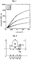
- Fig. 1 shows a relationship between the distance between the magnets (z) and the static repulsive force (F), when magnets of different size and mass are put in motion in the direction perpendicular to their surfaces.
- the internal magnetic moment is not easily affected by the magnetic field, and the strength of magnetization on a demagnetization curve barely fluctuates, and nearly completely maintains the saturation magnetization strength. For that reason, when the magnetic charge is evenly dispersed at the end surfaces of magnets, a hypothesized charge model is used in calculating the repulsive force acting between the magnets.
- (l) and (d) indicate the size of the magnets and ⁇ is the amount by which the two magnets are offset from each other, provided that the origin for calculation is located at the center point of each magnet.
- f m 1 2 ⁇ ( mg-F 0 ) 2 mk m
- f m 1 2 ⁇ ( mg-F 0 ) 2 mk m
- a constant repulsive force (b ⁇ 2 ) is continuously applied to a periodic external force to attenuate it. That is, by adjusting the locus of motion of the permanent magnets to control the spring constant, forced vibration is attenuated by the loaded mass, while being limited by the input.
- the value (4 ⁇ I) is a magnetic flux produced by the spontaneous magnetization I.
- the magnetic flux Hm indicates the diamagnetic field of the force by which the magnet weakens itself (self-demagnetization), and Hex is the external magnetic field that arises when magnetic poles oppose one another.
- multi polarization is effective to reduce Hm by creating a sequential (quasi) magnetic field with the neighboring magnets.
- the magnetic line of force will not extend outward.
- the magnetic line of force at a central portion hardly extend outward.
- the magnetic flux density at the edges is reduced, weakening the repulsive force. That is, the strength of the repulsive force is determined by the area of the opposing surfaces, the number of poles, and the distance between the magnets that is normally used.
- Figs. 4A to 4E depict various permanent magnets having an area of 75x75mm 2 and a thickness of 20mm and each having one to four magnetic poles on one side thereof.
- Fig. 5 depicts a relationship between the repulsive force and the distance between two identical magnets when like magnetic poles are opposed to each other.
- the two-pole magnets can be effectively utilized to form a magnetic circuit that is efficient to levitate the human body in a magnetic suspension unit.
- a leakage magnetic field is created between the neighboring magnets corresponding to magnetic domain walls, and when the faced magnets are brought near, a stronger repulsive force is obtained, reducing a sensation of bottoming or a bottom-end shock.
- Fig. 6 depicts a magnetic circuit M1 embodying the present invention, which includes a generally rectangular yoke, a separated two-pole magnet mounted on the yoke, and a single-pole magnet interposed between separated pieces of the two-pole magnet.
- the separated two-pole magnet can be regarded as two single-pole magnets having different magnetic poles formed on the same side.
- each piece (magnet) 8a, 8b of the separated two-pole magnet 8 (or each of the two single-pole magnets 8a, 8b) has magnetic poles formed in a direction perpendicular to a predetermined surface (upper surface in Fig. 6) of the yoke 6, and the two magnets 8a, 8b are spaced a predetermined distance with a single-pole magnet 10 interposed therebetween.
- a predetermined surface upper surface in Fig. 6
- the magnets 8a, 8b are spaced a predetermined distance with a single-pole magnet 10 interposed therebetween.
- the magnets 8a, 8b adjoin the magnet 10 with like magnetic poles opposed to each other.
- Fig. 7 depicts a modified form M2 of the magnetic circuit M1.
- the magnetic circuit M2 includes a yoke 6A having an elongated protrusion 6a integrally formed therewith at the center of one end surface thereof and also having two shoulder portions formed on respective sides of the elongated protrusion 6a.
- This magnetic circuit M3 also includes a single-pole magnet 10A mounted on the elongated protrusion 6a and two separated magnets 8a, 8b (two separated pieces of the two-pole magnet 8) mounted on the shoulder portions of the yoke 6A, respectively.
- Fig. 8 depicts another modified form M3 of the magnetic circuit M1.
- the magnetic circuit M3 includes a spacer 12 made of aluminum, copper or the like placed at the position where the elongated protrusion 6a is formed in the magnetic circuit M2. Accordingly, the yoke 6 shown in Fig. 8 is identical to the yoke 6 shown in Fig. 6.
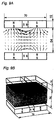
- Figs. 9A and 9B depict a magnetic flux distribution when a magneto-spring has been formed by two magnetic circuits of Fig. 6 that have a size (opposing area) of 70x70mm 2 and are spaced from each other with like magnetic poles opposed to each other.
- Figs. 10A and 10B depict a magnetic flux distribution when the magnetic poles of the magnet 10 interposed between the magnets 8a, 8b have been reversely arranged in the magnetic circuit of Fig. 6. As shown in Figs. 10A and 10B, the magnets 8a, 8b and the magnet 10 are arranged such that the magnetic poles thereof attract each other on the opposing side of the two magnetic circuits.
- Figs. 11A and 11B and Figs. 12A and 12B depict magnetic flux distributions when the two-pole magnet shown in Fig. 4B has a size of 70x70mm 2 and a size of 75x75mm 2 , respectively.
- the repulsive force becomes larger as the size of the magnetic circuit increases.
- the magnetic flux distribution can be controlled by changing the magnet arrangement, resulting in a magnetic circuit having a high repulsive force.
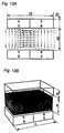
- Figs. 13A and 13B depict a magnetic flux distribution of a magneto-spring similar to the magneto-spring of Figs. 12A and 12B.
- the magneto-spring of Figs. 13A and 13B has magnets of an increased thickness that constitute two opposing magnetic circuits, and also has a reduced distance between the magnets.
- Figs. 14A and 14B depict a magnetic flux distribution when the two-pole magnets in the magneto-spring of Figs. 13A and 13B have been replaced by single-pole magnets.
- the repulsive force becomes larger as the size of the magnetic circuits becomes larger or as the distance between the magnetic circuits becomes smaller. Furthermore, the repulsive force can be increased by using the two-pole magnets in place of the single-pole magnets.
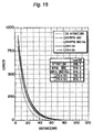
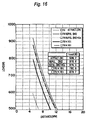
- Figs. 15 and 16 depict a relationship between the load (repulsive force) and the distance between the magnetic circuits in various magneto-springs.
- ATTRAC SN
- REPUL NS
- REPUL REPUL
- NS+Cu REPUL
- ⁇ 70x10t and ⁇ 75x10t denote the arrangement of Figs. 11A and 11B in which each magnetic circuit is made up of a two-pole magnet and the arrangement of Figs. 12A and 12B in which each magnetic circuit is similarly made up of a two-pole magnet, respectively.
- the graphs of Figs. 15 and 16 reveal that where the size of the magnetic circuits is the same, the repulsive force can be increased by the use of the magnetic circuits of Figs. 6 to 8 according to the present invention.
- a multi-pole magnet such as a three-pole magnet or a four-pole magnet can be also employed. That is, the repulsive force can be increased by inserting a repulsive magnet into separated pieces of the multi-pole magnet.
- a leakage magnetic field is created between neighboring magnets, and the repulsive force is increased by utilizing a magnetic field gradient at this time. Furthermore, when a repulsive magnet is inserted into separated pieces of the multi-pole magnet, the magnetic field gradient changes, thereby further increasing the repulsive force.
Landscapes
- Engineering & Computer Science (AREA)
- General Engineering & Computer Science (AREA)
- Power Engineering (AREA)
- Mechanical Engineering (AREA)
- Physics & Mathematics (AREA)
- Electromagnetism (AREA)
- Chemical & Material Sciences (AREA)
- Composite Materials (AREA)
- Vibration Prevention Devices (AREA)
- Toys (AREA)
- Dc Machiner (AREA)
- Magnetic Bearings And Hydrostatic Bearings (AREA)
Applications Claiming Priority (2)
| Application Number | Priority Date | Filing Date | Title |
|---|---|---|---|
| JP17966699 | 1999-06-25 | ||
| JP17966699A JP4159184B2 (ja) | 1999-06-25 | 1999-06-25 | 磁気ばね |
Publications (3)
| Publication Number | Publication Date |
|---|---|
| EP1063658A2 true EP1063658A2 (fr) | 2000-12-27 |
| EP1063658A3 EP1063658A3 (fr) | 2002-07-03 |
| EP1063658B1 EP1063658B1 (fr) | 2005-05-25 |
Family
ID=16069762
Family Applications (1)
| Application Number | Title | Priority Date | Filing Date |
|---|---|---|---|
| EP00113442A Expired - Lifetime EP1063658B1 (fr) | 1999-06-25 | 2000-06-24 | Circuit magnétique |
Country Status (7)
| Country | Link |
|---|---|
| US (1) | US6356177B1 (fr) |
| EP (1) | EP1063658B1 (fr) |
| JP (1) | JP4159184B2 (fr) |
| KR (1) | KR100346335B1 (fr) |
| CN (1) | CN1181504C (fr) |
| DE (1) | DE60020301T2 (fr) |
| TW (1) | TW454211B (fr) |
Families Citing this family (12)
| Publication number | Priority date | Publication date | Assignee | Title |
|---|---|---|---|---|
| US6747537B1 (en) * | 2002-05-29 | 2004-06-08 | Magnet Technology, Inc. | Strip magnets with notches |
| US6780653B2 (en) | 2002-06-06 | 2004-08-24 | Micron Technology, Inc. | Methods of forming magnetoresistive memory device assemblies |
| NL2005062A (en) * | 2009-08-12 | 2011-02-15 | Asml Netherlands Bv | A positioning system and a method for positioning a substage with respect to a frame. |
| US8264314B2 (en) * | 2009-10-20 | 2012-09-11 | Stream Power, Inc. | Magnetic arrays with increased magnetic flux |
| US8581778B2 (en) | 2010-07-19 | 2013-11-12 | Scidea Research, Inc. | Pulse compression system and method |
| WO2013114993A1 (fr) * | 2012-01-30 | 2013-08-08 | 三菱電機株式会社 | Circuit magnétique |
| US9263669B2 (en) | 2013-03-13 | 2016-02-16 | International Business Machines Corporation | Magnetic trap for cylindrical diamagnetic materials |
| CN103728006A (zh) * | 2014-01-24 | 2014-04-16 | 中国计量科学研究院 | 一种三维磁场电磁阻尼装置及方法 |
| DE102016009209B3 (de) * | 2016-08-01 | 2017-10-19 | Tdk-Micronas Gmbh | Messsystem |
| CN109516532A (zh) * | 2018-12-27 | 2019-03-26 | 中冶京诚工程技术有限公司 | 一种可升降式磁选机 |
| CN111370200A (zh) * | 2020-04-15 | 2020-07-03 | 杭州思创磁性器件有限公司 | 一种全维度自由吸合磁路结构 |
| CN112133516B (zh) * | 2020-09-15 | 2021-10-08 | 宁波韵升股份有限公司 | 一种拼接磁钢及工装及装配方法 |
Family Cites Families (6)
| Publication number | Priority date | Publication date | Assignee | Title |
|---|---|---|---|---|
| BE556726A (fr) * | 1956-04-18 | |||
| FR2223264A1 (en) * | 1973-03-27 | 1974-10-25 | Inst Wlokiennictwa | Wave shed loom magnetic shuttle drive - with friction force between shuttle and shedding mechanism eliminated |
| DE3832835A1 (de) * | 1988-09-28 | 1990-03-29 | Windhorst Beteiligungsgesellsc | Dauermagnetanordnung zum magnetischen entsperren der sperrvorrichtungen von warensicherungssystemen |
| JPH03108412A (ja) * | 1989-04-07 | 1991-05-08 | Sugawara Kogyo Kk | 播種育苗方法 |
| US5781005A (en) * | 1995-06-07 | 1998-07-14 | Allegro Microsystems, Inc. | Hall-effect ferromagnetic-article-proximity sensor |
| US6056872A (en) * | 1998-02-06 | 2000-05-02 | The Magnetizer Group, Inc. | Magnetic device for the treatment of fluids |
-
1999
- 1999-06-25 JP JP17966699A patent/JP4159184B2/ja not_active Expired - Fee Related
-
2000
- 2000-06-21 KR KR1020000034175A patent/KR100346335B1/ko not_active Expired - Fee Related
- 2000-06-23 TW TW089112420A patent/TW454211B/zh not_active IP Right Cessation
- 2000-06-23 US US09/599,728 patent/US6356177B1/en not_active Expired - Lifetime
- 2000-06-23 CN CNB001193384A patent/CN1181504C/zh not_active Expired - Fee Related
- 2000-06-24 EP EP00113442A patent/EP1063658B1/fr not_active Expired - Lifetime
- 2000-06-24 DE DE60020301T patent/DE60020301T2/de not_active Expired - Lifetime
Also Published As
| Publication number | Publication date |
|---|---|
| CN1181504C (zh) | 2004-12-22 |
| US6356177B1 (en) | 2002-03-12 |
| DE60020301D1 (de) | 2005-06-30 |
| KR100346335B1 (ko) | 2002-07-26 |
| JP4159184B2 (ja) | 2008-10-01 |
| TW454211B (en) | 2001-09-11 |
| EP1063658A3 (fr) | 2002-07-03 |
| EP1063658B1 (fr) | 2005-05-25 |
| KR20010007469A (ko) | 2001-01-26 |
| DE60020301T2 (de) | 2006-02-02 |
| JP2001012544A (ja) | 2001-01-16 |
| CN1279486A (zh) | 2001-01-10 |
Similar Documents
| Publication | Publication Date | Title |
|---|---|---|
| EP1063658B1 (fr) | Circuit magnétique | |
| Wu et al. | Analysis and design of a novel arrayed magnetic spring with high negative stiffness for low-frequency vibration isolation | |
| Carrella et al. | Force and displacement transmissibility of a nonlinear isolator with high-static-low-dynamic-stiffness | |
| JP4060146B2 (ja) | 負の剛性を持つ磁気スプリング・デバイス | |
| KR100455793B1 (ko) | 자기회로를 이용한 제진기구 | |
| US6035980A (en) | Magnetic spring having damping characteristics and vibration mechanism having same | |
| KR101600915B1 (ko) | 2차원 면진장치 | |
| EP1160482B1 (fr) | Ressort magnétique et mécanisme d'amortissement des vibrations le comprenant | |
| Janssen et al. | Design study on a magnetic gravity compensator with unequal magnet arrays | |
| EP1055838B1 (fr) | Mécanisme vibratoire | |
| Yan et al. | Electromagnetic shunt damping for shock isolation of nonlinear vibration isolators | |
| WO2019023041A1 (fr) | Système d'aimant permanent augmenté | |
| KR102141093B1 (ko) | 적층형 전자석 구조를 가지는 자기유변탄성체를 이용한 면진 장치 | |
| US8203243B2 (en) | Electromagnetic attraction type magnetic bearing and control method thereof | |
| Takada et al. | Influence of inductance properties on a magnetic levitation for thin-steel plates | |
| MIZUNO | Vibration isolation system using zero-power magnetic suspension | |
| JP2002021923A (ja) | 磁気減衰機構 | |
| WO2007070106A1 (fr) | Amortisseur magnetique pour temperatures variables | |
| JP4242961B2 (ja) | 磁気バネ | |
| Janssen et al. | Study of magnetic gravity compensator topologies using an abstraction in the analytical interaction equations | |
| JPH06158912A (ja) | 免震装置 | |
| KR101928017B1 (ko) | 면진 장치 | |
| Hoque et al. | A 3-DOF modular vibration isolation system using zero-power magnetic suspension with adjustable negative stiffness | |
| JP3924596B2 (ja) | 負の減衰特性を有する磁性バネ振動機構 | |
| Li et al. | A tunable'negative'stiffness system for vibration control |
Legal Events
| Date | Code | Title | Description |
|---|---|---|---|
| PUAI | Public reference made under article 153(3) epc to a published international application that has entered the european phase |
Free format text: ORIGINAL CODE: 0009012 |
|
| 17P | Request for examination filed |
Effective date: 20000810 |
|
| AK | Designated contracting states |
Kind code of ref document: A2 Designated state(s): AT BE CH CY DE DK ES FI FR GB GR IE IT LI LU MC NL PT SE |
|
| AX | Request for extension of the european patent |
Free format text: AL;LT;LV;MK;RO;SI |
|
| PUAL | Search report despatched |
Free format text: ORIGINAL CODE: 0009013 |
|
| AK | Designated contracting states |
Kind code of ref document: A3 Designated state(s): AT BE CH CY DE DK ES FI FR GB GR IE IT LI LU MC NL PT SE |
|
| AX | Request for extension of the european patent |
Free format text: AL;LT;LV;MK;RO;SI |
|
| RIC1 | Information provided on ipc code assigned before grant |
Free format text: 7H 01F 7/00 A, 7F 16F 6/00 B, 7H 01F 7/02 B |
|
| AKX | Designation fees paid |
Designated state(s): DE FR GB |
|
| 17Q | First examination report despatched |
Effective date: 20040128 |
|
| GRAP | Despatch of communication of intention to grant a patent |
Free format text: ORIGINAL CODE: EPIDOSNIGR1 |
|
| GRAS | Grant fee paid |
Free format text: ORIGINAL CODE: EPIDOSNIGR3 |
|
| GRAA | (expected) grant |
Free format text: ORIGINAL CODE: 0009210 |
|
| AK | Designated contracting states |
Kind code of ref document: B1 Designated state(s): DE FR GB |
|
| REG | Reference to a national code |
Ref country code: GB Ref legal event code: FG4D |
|
| REG | Reference to a national code |
Ref country code: IE Ref legal event code: FG4D |
|
| REF | Corresponds to: |
Ref document number: 60020301 Country of ref document: DE Date of ref document: 20050630 Kind code of ref document: P |
|
| PLBE | No opposition filed within time limit |
Free format text: ORIGINAL CODE: 0009261 |
|
| STAA | Information on the status of an ep patent application or granted ep patent |
Free format text: STATUS: NO OPPOSITION FILED WITHIN TIME LIMIT |
|
| ET | Fr: translation filed | ||
| 26N | No opposition filed |
Effective date: 20060228 |
|
| REG | Reference to a national code |
Ref country code: FR Ref legal event code: PLFP Year of fee payment: 17 |
|
| PGFP | Annual fee paid to national office [announced via postgrant information from national office to epo] |
Ref country code: GB Payment date: 20160624 Year of fee payment: 17 |
|
| PGFP | Annual fee paid to national office [announced via postgrant information from national office to epo] |
Ref country code: FR Payment date: 20160421 Year of fee payment: 17 |
|
| GBPC | Gb: european patent ceased through non-payment of renewal fee |
Effective date: 20170624 |
|
| REG | Reference to a national code |
Ref country code: FR Ref legal event code: ST Effective date: 20180228 |
|
| PG25 | Lapsed in a contracting state [announced via postgrant information from national office to epo] |
Ref country code: GB Free format text: LAPSE BECAUSE OF NON-PAYMENT OF DUE FEES Effective date: 20170624 |
|
| PG25 | Lapsed in a contracting state [announced via postgrant information from national office to epo] |
Ref country code: FR Free format text: LAPSE BECAUSE OF NON-PAYMENT OF DUE FEES Effective date: 20170630 |
|
| PGFP | Annual fee paid to national office [announced via postgrant information from national office to epo] |
Ref country code: DE Payment date: 20180703 Year of fee payment: 19 |
|
| REG | Reference to a national code |
Ref country code: DE Ref legal event code: R119 Ref document number: 60020301 Country of ref document: DE |
|
| PG25 | Lapsed in a contracting state [announced via postgrant information from national office to epo] |
Ref country code: DE Free format text: LAPSE BECAUSE OF NON-PAYMENT OF DUE FEES Effective date: 20200101 |