EP1063671A1 - Lampe und Verfahren zu deren Herstellung - Google Patents
Lampe und Verfahren zu deren Herstellung Download PDFInfo
- Publication number
- EP1063671A1 EP1063671A1 EP00112836A EP00112836A EP1063671A1 EP 1063671 A1 EP1063671 A1 EP 1063671A1 EP 00112836 A EP00112836 A EP 00112836A EP 00112836 A EP00112836 A EP 00112836A EP 1063671 A1 EP1063671 A1 EP 1063671A1
- Authority
- EP
- European Patent Office
- Prior art keywords
- sleeve
- lamp
- mounting portion
- groove
- lamp assembly
- Prior art date
- Legal status (The legal status is an assumption and is not a legal conclusion. Google has not performed a legal analysis and makes no representation as to the accuracy of the status listed.)
- Granted
Links
- 238000000034 method Methods 0.000 title claims description 12
- 239000002184 metal Substances 0.000 claims description 8
- 239000011521 glass Substances 0.000 claims description 7
- 230000008878 coupling Effects 0.000 claims description 6
- 238000010168 coupling process Methods 0.000 claims description 6
- 238000005859 coupling reaction Methods 0.000 claims description 6
- 238000007493 shaping process Methods 0.000 claims description 6
- WABPQHHGFIMREM-UHFFFAOYSA-N lead(0) Chemical compound [Pb] WABPQHHGFIMREM-UHFFFAOYSA-N 0.000 claims description 4
- 238000007789 sealing Methods 0.000 claims description 4
- 238000010438 heat treatment Methods 0.000 claims description 3
- 230000013011 mating Effects 0.000 claims description 3
- 238000003466 welding Methods 0.000 claims description 2
- 238000000465 moulding Methods 0.000 description 7
- 239000004033 plastic Substances 0.000 description 6
- 238000004519 manufacturing process Methods 0.000 description 2
- 239000002991 molded plastic Substances 0.000 description 2
- 239000004020 conductor Substances 0.000 description 1
- 239000000463 material Substances 0.000 description 1
- 230000002093 peripheral effect Effects 0.000 description 1
Images


Classifications
-
- H—ELECTRICITY
- H01—ELECTRIC ELEMENTS
- H01J—ELECTRIC DISCHARGE TUBES OR DISCHARGE LAMPS
- H01J5/00—Details relating to vessels or to leading-in conductors common to two or more basic types of discharge tubes or lamps
- H01J5/50—Means forming part of the tube or lamps for the purpose of providing electrical connection to it
- H01J5/54—Means forming part of the tube or lamps for the purpose of providing electrical connection to it supported by a separate part, e.g. base
- H01J5/58—Means for fastening the separate part to the vessel, e.g. by cement
- H01J5/60—Means for fastening the separate part to the vessel, e.g. by cement for fastening by mechanical means
-
- H—ELECTRICITY
- H01—ELECTRIC ELEMENTS
- H01J—ELECTRIC DISCHARGE TUBES OR DISCHARGE LAMPS
- H01J9/00—Apparatus or processes specially adapted for the manufacture, installation, removal, maintenance of electric discharge tubes, discharge lamps, or parts thereof; Recovery of material from discharge tubes or lamps
- H01J9/24—Manufacture or joining of vessels, leading-in conductors or bases
- H01J9/34—Joining base to vessel
-
- H—ELECTRICITY
- H01—ELECTRIC ELEMENTS
- H01J—ELECTRIC DISCHARGE TUBES OR DISCHARGE LAMPS
- H01J61/00—Gas-discharge or vapour-discharge lamps
- H01J61/02—Details
- H01J61/30—Vessels; Containers
- H01J61/34—Double-wall vessels or containers
Definitions
- the present invention relates to a lamp assembly, and more particularly, to a lamp assembly which includes retainer members by which a lamp sleeve is supported relative to a lamp base.
- the retainer members are firmly attached to the sleeve and provides 3-axis lamp focus before being firmly attached to the base.
- a method of producing such a lamp assembly is also provided.
- a lamp assembly which generally includes a lamp coupled to a lamp sleeve which is coupled to a lamp base by a retainer member. It is known to provide a high intensity discharge (HID) lamp in this manner.
- the conventional sleeve used with such an HID lamp is typically fabricated from glass and is generally cylindrical in configuration. Typically, the sleeve is attached to the lamp base by engaging an outer surface of the sleeve with a retainer member which is coupled to the lamp base.
- One concern regarding such structure is that although the outer peripheral surface of the sleeve is round, it is often not consistently round enough to provide a surface which can be satisfactorily held in place by the retainer member.
- any imperfections, such as scratches and nicks in the glass which are proximate to the retainer member have a tendency to propagate cracks during lamp assembly, and this ultimately causes lamp failure. In some instances the lamp may even explode. If the glass sleeve is replaced with a plastic sleeve, it will be necessary for thermal reasons to limit the lamp wattage.
- the retainer member is molded from plastic, and this also tends to limit the temperature capability of the lamp.
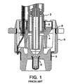
- processing of such plastic retainer member requires that the retainer member and the base be fabricated by metal insert molding. Further, it is necessary for three parts to be insert molded into such lamp base. An example of such a prior art lamp assembly is illustrated in FIG. 1.
- a lamp sleeve 2 is held in place by a molded plastic retainer member 4 which is attached to a molded plastic base 6.
- the retainer member 4 and base 6 contain a plurality of metal inserts 8 which must be provided by metal insert molding. Such a process is difficult and costly.
- Another object of the present invention is to provide a lamp assembly which obviates the disadvantages of the prior art.
- a further object of the present invention is to provide an improved and cost efficient lamp assembly.
- Yet another object of the present invention is to provide a lamp assembly having a sleeve and retainer arrangement which provides improved support for the sleeve.
- Another object of the present invention is to provide a lamp assembly having improved thermal capability.
- a further object of the present invention is to provide a lamp assembly wherein fabrication thereof includes simplified molding of the base and no molding of the sleeve retainer member.
- Yet another object of the present invention is to provide a method of producing the lamp assembly of the present invention.
- a lamp assembly comprising a sleeve extending in the direction of a longitudinal axis from a first sleeve end to an opposite second sleeve end.
- An outer surface of the sleeve comprises at least one groove which extends in a plane which is transverse to the longitudinal axis and is located between the first sleeve end and the second sleeve end.
- a base component is provided having a mounting portion and comprising contacts structured and arranged for connection with a connector.
- a lamp is provided which extends in the sleeve and comprises lead wires coupled to the contacts.
- a pair of retainer members is provided each of which extends from a first end segment to an opposite second end segment.
- the groove is disposed between, and mated with, the first end segments.
- the second end segments are structured and arranged to be (a) tensioned relative to the mounting portion in a first mode, and (b) fixed to the mounting portion in a second mode.
- a method of producing a lamp assembly of the present invention comprises the steps of forming at least one circumferential groove in an outer surface of a lamp sleeve so that the groove extends in a plane which is transverse to a longitudinal axis of the lamp sleeve; affixing a lamp internal of the lamp sleeve; forming a base component having a mounting portion; shaping a first end segment of respective first and second retainer members so as to be engagable and matable with the groove; shaping a second end segment of the respective first and second retainer members so as to be tensioned relative to the mounting portion when the first and second retainer members are coupled to the mounting portion; attaching the first and second retainer members to the sleeve such that each first end segment contacts and mates with the groove; coupling the first and second retainer members to the base component; focusing the lamp relative to the base component by moving the retainer members relative to the mounting portion until the lamp is focused; and fastening each second end segment to the
- the lamp base assembly of the present invention comprises a sleeve attached to a pair of retainer members which are attached to a base component having contacts adapted to be connected to a connector in a conventional manner.
- a lamp is positioned within the sleeve and includes lead wires coupled to the contacts.
- the sleeve includes a groove which is shaped in such a manner that it matches the pair of retainer members between which the sleeve is supported.
- the pair of retainer members is adapted (a) to be tensioned relative to the base component in a first mode during which the lamp may be oriented relative to the base component by being slid in or out, and titled back and forth or right and left in the direction of Z-,X- or Y-axes, respectively, to position the lamp as desired, and (b) to be fixed to the base component in a second mode to hold the lamp in place in such desired position.
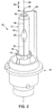
- FIGS. 2 to 5 illustrate one embodiment of such a lamp assembly.
- a lamp assembly 10 which includes a glass sleeve 12 attached to a pair of retainer members including a first retainer member 14 and a second retainer member 16.
- the lamp assembly 10 is an HID lamp assembly which may be used in a conventional HID automotive headlamp.
- the retainer members 14 and 16 are attached to a base component 18.
- a lamp 20 is positioned within the sleeve 12 and includes lead wires 22 and 24 which are coupled to base component contacts as described herein.
- the sleeve extends in the direction 26 of a longitudinal axis 28 from a closed first sleeve end 30 to an opposite open second sleeve end 32.
- the sleeve of the present invention includes an outer surface comprising at least one groove which extends in a plane which is transverse to the longitudinal axis of the sleeve and is located between the sleeve ends.
- the sleeve 12 is generally cylindrical and includes an outer surface 34 comprising a single circumferential groove 36 which extends 360° about the longitudinal axis 28.
- the groove 36 extends in a plane identified in FIGS. 4 and 5 by line 38 which is transverse to axis 28 and is located between the closed sleeve end 30 and the open sleeve end 32.
- the sleeve 12 comprises a precisely roll-formed groove 36 in the outer surface 34.
- groove 36 may be formed by coupling the sleeve 12 to a lathe, heating the sleeve by positioning a flame adjacent the surface area where the groove is to be provided, and engaging such heated surface area with a precisely positioned wheel or roller. The wheel is rolled in the heated sleeve material to form the circumferential groove 36. In this manner, a glass sleeve having a consistent, known contact surface area may be provided having no imperfections such as scratches or nicks.
- the sleeve 12 comprises an inner surface 40 which comprises a lamp sealing portion 42 which extends 360° about longitudinal axis 28 in plane 38.
- the lamp 20 may be a conventional light source such as an arc tube.
- the lamp 20 is affixed within the surrounding sleeve 12.
- the lamp 20 extends in the sleeve 12 and is sealed therein in a conventional manner where an outer surface 44 of the lamp abuts the lamp sealing portion 42.
- the lead wire 22 of the lamp 20 is coupled to contact 46 of the base component 18 in a conventional manner.
- the lead wire 24 is coupled to the contact 48 through a conductor 50, in a conventional manner.
- the lead wires 22 and 24 extend in the direction 26 of longitudinal axis 28.
- the lead wires 22 and 24 are substantially straight and extend from respective first ends 52 and 54 within the lamp 20 to respective second ends 56 and 58 outside of the sleeve 12.
- the base component of the present invention comprises a mounting portion to which the retainer members of the present invention are attached as described herein.
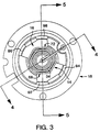
- a plastic base component 18 is provided which comprises an inner sleeve 60 having an outer surface 62 and an outer sleeve 64 having an inner surface 66.
- the inner sleeve 60 is disposed concentric relative to the outer sleeve 64, and both sleeves extend in the direction 26 of longitudinal axis 28.
- the base component 18 is a molded non-conductive plastic unit having only two metal insert molded components in the form of contacts 46 and 48.
- Each retainer member of the present invention extends from a first end segment to an opposite second end segment.
- Each retainer member may be formed from metal by a conventional stamping operation. The use of metal increases the temperature capability of the lamp assembly allowing for the use of higher wattage lamps.
- the retainer members are identical.
- the retainer members are structured and arranged such that (a) the first end segments engage and mate with the groove extending into the outer surface of the sleeve, and (b) the second end segments are resilient so that they may be tensioned relative to the mounting portion of the base component in a first mode.
- the second end segments are fixed to the mounting portion in a second mode.
- the retainer member 14 extends from an end segment 68 to an opposite end segment 70
- the retainer member 16 extends from an end segment 72 to an opposite end segment 74.
- the groove 36 in the outer surface 34 of the sleeve 12 is disposed between and mates with the end segments 68 and 72 of respective retainer members 14 and 16.
- the segments 68 and 72 each comprises a band having opposite ends, the opposite ends of one band overlapping with and being attached to respective opposite ends of the other band.
- the end segment 68 of the retainer member 14 comprises a generally U-shaped band 76 shaped to comprise two indents 78, curved convex towards axis 28, and a first leg 80 and a second leg 82.
- the end segment 72 of the retainer member 16 comprises a generally U-shaped band 84 shaped to comprise two identical indents 86, curved convex towards axis 28, and a first leg 88 and a second leg 90.
- the roll formed groove 36 and detents 78, 86 are configured such that the surface of the groove contacts and matches or mates with the detents when the device is assembled.
- the legs 80 and 82 overlap with and are attached to respective legs 88 and 90 as, for example, by laser welding.
- a portion of the sleeve 12 is disposed between the opposing U-shaped bands 76 and 84, and the detents 78 and 86 are disposed within and mate with the groove 36.
- the detents 78 and 86 are fitted into the groove 36 with the ends of band legs 80 and 82 overlapping respective ends of legs 88 and 90.
- the retainer members 14 and 16 are then pushed together to a set force, and the respective ends are laser welded together thereby locking the detents 78 and 86 in the groove 36.
- the end segments 70 and 74 of respective retainer members 14 and 16 are resilient so that they may be tensioned relative to a mounting portion of the base component 18 in a first mode.
- the end segment 70 comprises curved skirts 92 and 94
- the end segment 74 comprises curved skirts 96 and 98.
- Each skirt 92, 94, 96 and 98 is concave relative to axis 28.
- the inner surface 66 of the sleeve 64 of base component 18 serves as a mounting portion of the base component.
- the skirts 92, 94, 96 and 98 are structured and arranged to engage and be biased against the inner surface 66 when the sleeve 12 has been attached to the retainer members 14 and 16 as described above, and the retainer members are inserted into the annular opening 100 between surfaces 62 and 66.
- the skirts 92, 94, 96 and 98 engage and are tensioned relative to a mounting portion of the base component 18 by being expanded away from the longitudinal axis 28 sufficiently to be biased against surface 66 to couple the retainer members to the mounting portion when inserted into opening 100, in a first mode.
- the outer surface 62 of the sleeve 60 of the base component 18 may serve as the mounting portion of the base component.
- the skirts 92, 94, 96 and 98 engage and are tensioned relative to a mounting portion of the base component 18 by being compressed towards the longitudinal axis 28 sufficiently to be biased against the outer surface 62 to couple the retainer members to the mounting portion when inserted into opening 100, in a first mode.
- the lamp may be focused using a three axis motion.
- the retainer members, the sleeve supported thereby, and the lamp supported within the sleeve may be oriented as a unit relative to the base component by being slid in the direction of a Z-axis, and tilted back and forth in the direction of an X-axis and left and right in the direction of a Y-axis, to the extent required to properly focus the lamp.
- the unit comprising the sleeve 12, retainer members 14, 16 and lamp 20 may be oriented relative to the base component 18 by sliding the skirts 92, 94, 96 and 98 relative to surface 66 in a Z-direction identified by the direction 26 of axis 28, and tilting or otherwise pivoting the skirts relative to surface 66 back and forth and right and left in the direction of any X-axis and any Y-axis relative to axis 28. In this manner, three axis focusing of lamp 20 is provided while maintaining contact between the retainer members 14 and 16 and the base component 18.
- the focused lamp may be held in place by fixing the retainer members to the base component, in a second mode.
- the second end segments of the retainer members may be melt fused to the base component thereby fixing in place the unit formed by the sleeve, resilient members and lamp.
- the end segments 70 and 74 may be attached to the base component 18 by melt fusing the respective skirts 92, 94, 96 and 98 to the sleeve 64 at the mounting portion of the base component formed by the inner surface 66, in a conventional manner such as by heating using radio frequency heat.
- the skirts 92, 94, 96 and 98 may each comprise at least one aperture 102. In this manner, during melt fusing portions of the melted base component 18 will flow through respective apertures 102 to improve the attachment of the skirts 92, 94, 96 and 98 to the surface 66.
- the lamp assembly of the present invention is much simpler, less expensive and easier to assemble than previous designs yet functions at least just as well.
- molding of the plastic base is simplified, and no molding is required of the retainer members.
- the retainer members may be identical, and each may be stamped from a single piece of metal. Production of the components and the assembled device is very repeatable.
- the lamp assembly is very robust, the mating groove 36 and retainer members 14, 16 firmly and safely coupling the sleeve 12 to the retainer members.
- Another advantage is that the focusing pivot points provided by the skirts 92, 94, 96 and 98 are positioned relatively low within the base component 18. As a result, the lamp electrodes will rotate in a larger arc during focusing and therefor stay straighter.
Landscapes
- Engineering & Computer Science (AREA)
- Manufacturing & Machinery (AREA)
- Fastening Of Light Sources Or Lamp Holders (AREA)
- Common Detailed Techniques For Electron Tubes Or Discharge Tubes (AREA)
- Non-Portable Lighting Devices Or Systems Thereof (AREA)
- Vessels And Coating Films For Discharge Lamps (AREA)
- Glass Compositions (AREA)
Applications Claiming Priority (2)
| Application Number | Priority Date | Filing Date | Title |
|---|---|---|---|
| US09/340,175 US6203169B1 (en) | 1999-06-25 | 1999-06-25 | Lamp and method of producing same |
| US340175 | 1999-06-25 |
Publications (2)
| Publication Number | Publication Date |
|---|---|
| EP1063671A1 true EP1063671A1 (de) | 2000-12-27 |
| EP1063671B1 EP1063671B1 (de) | 2004-09-15 |
Family
ID=23332209
Family Applications (1)
| Application Number | Title | Priority Date | Filing Date |
|---|---|---|---|
| EP00112836A Expired - Lifetime EP1063671B1 (de) | 1999-06-25 | 2000-06-17 | Lampe und Verfahren zu deren Herstellung |
Country Status (5)
| Country | Link |
|---|---|
| US (1) | US6203169B1 (de) |
| EP (1) | EP1063671B1 (de) |
| AT (1) | ATE276582T1 (de) |
| DE (1) | DE60013700T2 (de) |
| ES (1) | ES2226659T3 (de) |
Cited By (3)
| Publication number | Priority date | Publication date | Assignee | Title |
|---|---|---|---|---|
| WO2002033724A1 (en) * | 2000-10-13 | 2002-04-25 | General Electric Company | Base for low pressure discharge lamps |
| WO2005071794A3 (en) * | 2004-01-22 | 2007-03-01 | Koninkl Philips Electronics Nv | A lamp and a method of attaching a burner to a cap of lamp |
| WO2011009686A3 (de) * | 2009-07-21 | 2011-12-15 | Osram Ag | Entladungslampe und verfahren zur herstellung einer derartigen entladungslampe |
Families Citing this family (30)
| Publication number | Priority date | Publication date | Assignee | Title |
|---|---|---|---|---|
| US7002285B2 (en) * | 2003-01-03 | 2006-02-21 | General Electric Company | Discharge lamp with bulb fixture arrangement and method for manufacturing the same |
| DE10325553A1 (de) * | 2003-06-05 | 2004-12-23 | Patent-Treuhand-Gesellschaft für elektrische Glühlampen mbH | Zweiseitig verschlossene Lampe |
| US7097331B2 (en) * | 2004-09-24 | 2006-08-29 | Variable Luminaire Ltd. | Safety switch control structure |
| WO2006130751A1 (en) * | 2005-06-02 | 2006-12-07 | Gp Ltd | Light string system |
| US7943211B2 (en) * | 2007-12-06 | 2011-05-17 | Willis Electric Co., Ltd. | Three dimensional displays having deformable constructions |
| US20090190359A1 (en) * | 2008-01-28 | 2009-07-30 | Cindex Holdings Limited (A Hong Kong Corporation) | Led light string system |
| US7980871B2 (en) * | 2008-10-20 | 2011-07-19 | Polygroup Macau Limited (Bvi) | Light string system |
| US20100289415A1 (en) * | 2009-05-18 | 2010-11-18 | Johnny Chen | Energy efficient decorative lighting |
| EP2425442B1 (de) * | 2009-09-18 | 2012-11-14 | Koninklijke Philips Electronics N.V. | Vorrichtung zur befestigung des brenners einer entladungslampe |
| US20110085327A1 (en) * | 2009-10-14 | 2011-04-14 | Johnny Chen | Decorative light display with LEDs |
| US8235737B2 (en) | 2009-12-09 | 2012-08-07 | Polygroup Macau Limited (Bvi) | Light string system |
| US8568015B2 (en) | 2010-09-23 | 2013-10-29 | Willis Electric Co., Ltd. | Decorative light string for artificial lighted tree |
| US8298633B1 (en) | 2011-05-20 | 2012-10-30 | Willis Electric Co., Ltd. | Multi-positional, locking artificial tree trunk |
| US8569960B2 (en) | 2011-11-14 | 2013-10-29 | Willis Electric Co., Ltd | Conformal power adapter for lighted artificial tree |
| US9157587B2 (en) | 2011-11-14 | 2015-10-13 | Willis Electric Co., Ltd. | Conformal power adapter for lighted artificial tree |
| US8876321B2 (en) | 2011-12-09 | 2014-11-04 | Willis Electric Co., Ltd. | Modular lighted artificial tree |
| US9179793B2 (en) | 2012-05-08 | 2015-11-10 | Willis Electric Co., Ltd. | Modular tree with rotation-lock electrical connectors |
| US10206530B2 (en) | 2012-05-08 | 2019-02-19 | Willis Electric Co., Ltd. | Modular tree with locking trunk |
| US9572446B2 (en) | 2012-05-08 | 2017-02-21 | Willis Electric Co., Ltd. | Modular tree with locking trunk and locking electrical connectors |
| US9044056B2 (en) | 2012-05-08 | 2015-06-02 | Willis Electric Co., Ltd. | Modular tree with electrical connector |
| US9439528B2 (en) | 2013-03-13 | 2016-09-13 | Willis Electric Co., Ltd. | Modular tree with locking trunk and locking electrical connectors |
| US9671074B2 (en) | 2013-03-13 | 2017-06-06 | Willis Electric Co., Ltd. | Modular tree with trunk connectors |
| US9157588B2 (en) | 2013-09-13 | 2015-10-13 | Willis Electric Co., Ltd | Decorative lighting with reinforced wiring |
| US9140438B2 (en) | 2013-09-13 | 2015-09-22 | Willis Electric Co., Ltd. | Decorative lighting with reinforced wiring |
| US11306881B2 (en) | 2013-09-13 | 2022-04-19 | Willis Electric Co., Ltd. | Tangle-resistant decorative lighting assembly |
| US10267464B2 (en) | 2015-10-26 | 2019-04-23 | Willis Electric Co., Ltd. | Tangle-resistant decorative lighting assembly |
| US9894949B1 (en) | 2013-11-27 | 2018-02-20 | Willis Electric Co., Ltd. | Lighted artificial tree with improved electrical connections |
| US8870404B1 (en) | 2013-12-03 | 2014-10-28 | Willis Electric Co., Ltd. | Dual-voltage lighted artificial tree |
| US9883566B1 (en) | 2014-05-01 | 2018-01-30 | Willis Electric Co., Ltd. | Control of modular lighted artificial trees |
| US10683974B1 (en) | 2017-12-11 | 2020-06-16 | Willis Electric Co., Ltd. | Decorative lighting control |
Citations (2)
| Publication number | Priority date | Publication date | Assignee | Title |
|---|---|---|---|---|
| EP0321866A2 (de) * | 1987-12-22 | 1989-06-28 | Patent-Treuhand-Gesellschaft für elektrische Glühlampen mbH | Hochdruckentladungslampe |
| US5627428A (en) * | 1994-08-04 | 1997-05-06 | Patent-Treuhand-Gesellschaft F. Elektrisohe Cluehlampen Mbh | Single-based high-pressure discharge lamp particularly for automotive-type headlights |
Family Cites Families (4)
| Publication number | Priority date | Publication date | Assignee | Title |
|---|---|---|---|---|
| JPS5688274A (en) * | 1979-12-20 | 1981-07-17 | Tokyo Shibaura Electric Co | Light source |
| FR2630193B1 (fr) * | 1988-04-19 | 1990-07-20 | Ficea | Systeme de montage de lampes de differents types sur le reflecteur d'un projecteur |
| DE9012292U1 (de) * | 1990-08-27 | 1990-10-31 | Patent-Treuhand-Gesellschaft für elektrische Glühlampen mbH, 8000 München | Kittlos gesockelte elektrische Lampe |
| US5239226A (en) * | 1990-12-14 | 1993-08-24 | General Electric Company | Replaceable lamp assembly for automotive headlamps |
-
1999
- 1999-06-25 US US09/340,175 patent/US6203169B1/en not_active Expired - Fee Related
-
2000
- 2000-06-17 DE DE60013700T patent/DE60013700T2/de not_active Expired - Fee Related
- 2000-06-17 ES ES00112836T patent/ES2226659T3/es not_active Expired - Lifetime
- 2000-06-17 EP EP00112836A patent/EP1063671B1/de not_active Expired - Lifetime
- 2000-06-17 AT AT00112836T patent/ATE276582T1/de not_active IP Right Cessation
Patent Citations (2)
| Publication number | Priority date | Publication date | Assignee | Title |
|---|---|---|---|---|
| EP0321866A2 (de) * | 1987-12-22 | 1989-06-28 | Patent-Treuhand-Gesellschaft für elektrische Glühlampen mbH | Hochdruckentladungslampe |
| US5627428A (en) * | 1994-08-04 | 1997-05-06 | Patent-Treuhand-Gesellschaft F. Elektrisohe Cluehlampen Mbh | Single-based high-pressure discharge lamp particularly for automotive-type headlights |
Cited By (4)
| Publication number | Priority date | Publication date | Assignee | Title |
|---|---|---|---|---|
| WO2002033724A1 (en) * | 2000-10-13 | 2002-04-25 | General Electric Company | Base for low pressure discharge lamps |
| WO2005071794A3 (en) * | 2004-01-22 | 2007-03-01 | Koninkl Philips Electronics Nv | A lamp and a method of attaching a burner to a cap of lamp |
| WO2011009686A3 (de) * | 2009-07-21 | 2011-12-15 | Osram Ag | Entladungslampe und verfahren zur herstellung einer derartigen entladungslampe |
| JP2012533859A (ja) * | 2009-07-21 | 2012-12-27 | オスラム アクチエンゲゼルシャフト | 放電ランプ、および放電ランプの製造方法 |
Also Published As
| Publication number | Publication date |
|---|---|
| ES2226659T3 (es) | 2005-04-01 |
| DE60013700D1 (de) | 2004-10-21 |
| ATE276582T1 (de) | 2004-10-15 |
| DE60013700T2 (de) | 2005-09-29 |
| EP1063671B1 (de) | 2004-09-15 |
| US6203169B1 (en) | 2001-03-20 |
Similar Documents
| Publication | Publication Date | Title |
|---|---|---|
| EP1063671B1 (de) | Lampe und Verfahren zu deren Herstellung | |
| US6080019A (en) | Lamp and lamp base assembly | |
| US6137228A (en) | Metal halide lamps with tungsten coils having varying pitches and inner diameters | |
| US6270235B1 (en) | Lamp and lamp based assembly | |
| EP0567925B1 (de) | Zusammensetzung einer Entladungslampe hoher Intensität für Kraftfahrzeugscheinwerfer | |
| JPH09213208A (ja) | 電 球 | |
| US5742114A (en) | Lamp envelope with a metal clamping member and a fixation member | |
| KR100852472B1 (ko) | 방전 램프 및 그 제조 방법과, 고정 장치 | |
| KR100905726B1 (ko) | 램프, 램프 제조 방법 및 램프의 연속체 | |
| US5696424A (en) | Alignment structure for headlamp capsule | |
| US5659221A (en) | High intensity discharge headlamp assembly | |
| EP0309041B1 (de) | Gesockelte elektrische Lampe | |
| US4622486A (en) | Halogen lamp device for headlamp | |
| JP4184967B2 (ja) | ヘッドライトランプ | |
| KR100503980B1 (ko) | 캡이 씌워진 전기 램프 | |
| US5130911A (en) | Two piece lamp holder | |
| US5654608A (en) | Capped electric lamp | |
| NL7908214A (nl) | Elektrische gloeilamp. | |
| US7282847B2 (en) | Electric lamp and manufacturing method | |
| US6657369B1 (en) | Lamp with reflector and method of manufacturing the same | |
| US5272409A (en) | Capped lamp/reflector unit | |
| CN1322532C (zh) | 白炽电灯及插座组件 | |
| KR100469209B1 (ko) | 전기램프 | |
| JP2000353421A (ja) | ランプ | |
| KR100432286B1 (ko) | 원통형램프보유지지용금속스트랩 |
Legal Events
| Date | Code | Title | Description |
|---|---|---|---|
| PUAI | Public reference made under article 153(3) epc to a published international application that has entered the european phase |
Free format text: ORIGINAL CODE: 0009012 |
|
| AK | Designated contracting states |
Kind code of ref document: A1 Designated state(s): AT BE CH CY DE DK ES FI FR GB GR IE IT LI LU MC NL PT SE |
|
| AX | Request for extension of the european patent |
Free format text: AL;LT;LV;MK;RO;SI |
|
| 17P | Request for examination filed |
Effective date: 20010122 |
|
| AKX | Designation fees paid |
Free format text: AT BE CH CY DE DK ES FI FR GB GR IE IT LI LU MC NL PT SE |
|
| 17Q | First examination report despatched |
Effective date: 20030411 |
|
| GRAP | Despatch of communication of intention to grant a patent |
Free format text: ORIGINAL CODE: EPIDOSNIGR1 |
|
| GRAS | Grant fee paid |
Free format text: ORIGINAL CODE: EPIDOSNIGR3 |
|
| GRAA | (expected) grant |
Free format text: ORIGINAL CODE: 0009210 |
|
| AK | Designated contracting states |
Kind code of ref document: B1 Designated state(s): AT BE CH CY DE DK ES FI FR GB GR IE IT LI LU MC NL PT SE |
|
| PG25 | Lapsed in a contracting state [announced via postgrant information from national office to epo] |
Ref country code: LI Free format text: LAPSE BECAUSE OF FAILURE TO SUBMIT A TRANSLATION OF THE DESCRIPTION OR TO PAY THE FEE WITHIN THE PRESCRIBED TIME-LIMIT Effective date: 20040915 Ref country code: FI Free format text: LAPSE BECAUSE OF FAILURE TO SUBMIT A TRANSLATION OF THE DESCRIPTION OR TO PAY THE FEE WITHIN THE PRESCRIBED TIME-LIMIT Effective date: 20040915 Ref country code: CH Free format text: LAPSE BECAUSE OF FAILURE TO SUBMIT A TRANSLATION OF THE DESCRIPTION OR TO PAY THE FEE WITHIN THE PRESCRIBED TIME-LIMIT Effective date: 20040915 Ref country code: AT Free format text: LAPSE BECAUSE OF FAILURE TO SUBMIT A TRANSLATION OF THE DESCRIPTION OR TO PAY THE FEE WITHIN THE PRESCRIBED TIME-LIMIT Effective date: 20040915 |
|
| REG | Reference to a national code |
Ref country code: CH Ref legal event code: EP Ref country code: GB Ref legal event code: FG4D |
|
| REG | Reference to a national code |
Ref country code: IE Ref legal event code: FG4D |
|
| REF | Corresponds to: |
Ref document number: 60013700 Country of ref document: DE Date of ref document: 20041021 Kind code of ref document: P |
|
| PG25 | Lapsed in a contracting state [announced via postgrant information from national office to epo] |
Ref country code: SE Free format text: LAPSE BECAUSE OF FAILURE TO SUBMIT A TRANSLATION OF THE DESCRIPTION OR TO PAY THE FEE WITHIN THE PRESCRIBED TIME-LIMIT Effective date: 20041215 Ref country code: DK Free format text: LAPSE BECAUSE OF FAILURE TO SUBMIT A TRANSLATION OF THE DESCRIPTION OR TO PAY THE FEE WITHIN THE PRESCRIBED TIME-LIMIT Effective date: 20041215 Ref country code: GR Free format text: LAPSE BECAUSE OF FAILURE TO SUBMIT A TRANSLATION OF THE DESCRIPTION OR TO PAY THE FEE WITHIN THE PRESCRIBED TIME-LIMIT Effective date: 20041215 |
|
| REG | Reference to a national code |
Ref country code: CH Ref legal event code: PL |
|
| REG | Reference to a national code |
Ref country code: ES Ref legal event code: FG2A Ref document number: 2226659 Country of ref document: ES Kind code of ref document: T3 |
|
| PGFP | Annual fee paid to national office [announced via postgrant information from national office to epo] |
Ref country code: ES Payment date: 20050613 Year of fee payment: 6 |
|
| PG25 | Lapsed in a contracting state [announced via postgrant information from national office to epo] |
Ref country code: IE Free format text: LAPSE BECAUSE OF NON-PAYMENT OF DUE FEES Effective date: 20050617 Ref country code: LU Free format text: LAPSE BECAUSE OF NON-PAYMENT OF DUE FEES Effective date: 20050617 Ref country code: CY Free format text: LAPSE BECAUSE OF FAILURE TO SUBMIT A TRANSLATION OF THE DESCRIPTION OR TO PAY THE FEE WITHIN THE PRESCRIBED TIME-LIMIT Effective date: 20050617 |
|
| PG25 | Lapsed in a contracting state [announced via postgrant information from national office to epo] |
Ref country code: MC Free format text: LAPSE BECAUSE OF NON-PAYMENT OF DUE FEES Effective date: 20050630 |
|
| PLBE | No opposition filed within time limit |
Free format text: ORIGINAL CODE: 0009261 |
|
| STAA | Information on the status of an ep patent application or granted ep patent |
Free format text: STATUS: NO OPPOSITION FILED WITHIN TIME LIMIT |
|
| ET | Fr: translation filed | ||
| 26N | No opposition filed |
Effective date: 20050616 |
|
| REG | Reference to a national code |
Ref country code: IE Ref legal event code: MM4A |
|
| PGFP | Annual fee paid to national office [announced via postgrant information from national office to epo] |
Ref country code: GB Payment date: 20060613 Year of fee payment: 7 |
|
| PGFP | Annual fee paid to national office [announced via postgrant information from national office to epo] |
Ref country code: NL Payment date: 20060616 Year of fee payment: 7 |
|
| PGFP | Annual fee paid to national office [announced via postgrant information from national office to epo] |
Ref country code: BE Payment date: 20060620 Year of fee payment: 7 |
|
| PGFP | Annual fee paid to national office [announced via postgrant information from national office to epo] |
Ref country code: FR Payment date: 20060623 Year of fee payment: 7 |
|
| PGFP | Annual fee paid to national office [announced via postgrant information from national office to epo] |
Ref country code: IT Payment date: 20060630 Year of fee payment: 7 |
|
| BERE | Be: lapsed |
Owner name: *OSRAM SYLVANIA INC. Effective date: 20070630 |
|
| PG25 | Lapsed in a contracting state [announced via postgrant information from national office to epo] |
Ref country code: PT Free format text: LAPSE BECAUSE OF NON-PAYMENT OF DUE FEES Effective date: 20050215 |
|
| GBPC | Gb: european patent ceased through non-payment of renewal fee |
Effective date: 20070617 |
|
| NLV4 | Nl: lapsed or anulled due to non-payment of the annual fee |
Effective date: 20080101 |
|
| PG25 | Lapsed in a contracting state [announced via postgrant information from national office to epo] |
Ref country code: BE Free format text: LAPSE BECAUSE OF NON-PAYMENT OF DUE FEES Effective date: 20070630 |
|
| REG | Reference to a national code |
Ref country code: FR Ref legal event code: ST Effective date: 20080229 |
|
| PG25 | Lapsed in a contracting state [announced via postgrant information from national office to epo] |
Ref country code: NL Free format text: LAPSE BECAUSE OF NON-PAYMENT OF DUE FEES Effective date: 20080101 |
|
| PG25 | Lapsed in a contracting state [announced via postgrant information from national office to epo] |
Ref country code: GB Free format text: LAPSE BECAUSE OF NON-PAYMENT OF DUE FEES Effective date: 20070617 |
|
| REG | Reference to a national code |
Ref country code: ES Ref legal event code: FD2A Effective date: 20070618 |
|
| PG25 | Lapsed in a contracting state [announced via postgrant information from national office to epo] |
Ref country code: FR Free format text: LAPSE BECAUSE OF NON-PAYMENT OF DUE FEES Effective date: 20070702 |
|
| PG25 | Lapsed in a contracting state [announced via postgrant information from national office to epo] |
Ref country code: ES Free format text: LAPSE BECAUSE OF NON-PAYMENT OF DUE FEES Effective date: 20070618 |
|
| PGFP | Annual fee paid to national office [announced via postgrant information from national office to epo] |
Ref country code: DE Payment date: 20080818 Year of fee payment: 9 |
|
| PG25 | Lapsed in a contracting state [announced via postgrant information from national office to epo] |
Ref country code: IT Free format text: LAPSE BECAUSE OF NON-PAYMENT OF DUE FEES Effective date: 20070617 |
|
| PG25 | Lapsed in a contracting state [announced via postgrant information from national office to epo] |
Ref country code: DE Free format text: LAPSE BECAUSE OF NON-PAYMENT OF DUE FEES Effective date: 20100101 |