EP1063678A2 - Dispositif de production d'un plasma excité par microondes dans une cavité - Google Patents
Dispositif de production d'un plasma excité par microondes dans une cavité Download PDFInfo
- Publication number
- EP1063678A2 EP1063678A2 EP00112949A EP00112949A EP1063678A2 EP 1063678 A2 EP1063678 A2 EP 1063678A2 EP 00112949 A EP00112949 A EP 00112949A EP 00112949 A EP00112949 A EP 00112949A EP 1063678 A2 EP1063678 A2 EP 1063678A2
- Authority
- EP
- European Patent Office
- Prior art keywords
- microwave
- plasma
- barrier
- radiators
- chamber
- Prior art date
- Legal status (The legal status is an assumption and is not a legal conclusion. Google has not performed a legal analysis and makes no representation as to the accuracy of the status listed.)
- Withdrawn
Links
Images


Classifications
-
- H—ELECTRICITY
- H01—ELECTRIC ELEMENTS
- H01J—ELECTRIC DISCHARGE TUBES OR DISCHARGE LAMPS
- H01J37/00—Discharge tubes with provision for introducing objects or material to be exposed to the discharge, e.g. for the purpose of examination or processing thereof
- H01J37/32—Gas-filled discharge tubes
- H01J37/32009—Arrangements for generation of plasma specially adapted for examination or treatment of objects, e.g. plasma sources
- H01J37/32192—Microwave generated discharge
-
- H—ELECTRICITY
- H01—ELECTRIC ELEMENTS
- H01J—ELECTRIC DISCHARGE TUBES OR DISCHARGE LAMPS
- H01J37/00—Discharge tubes with provision for introducing objects or material to be exposed to the discharge, e.g. for the purpose of examination or processing thereof
- H01J37/32—Gas-filled discharge tubes
- H01J37/32431—Constructional details of the reactor
- H01J37/32623—Mechanical discharge control means
Definitions
- the invention relates to a device according to the preamble of patent claim 1.
- Plasmas are ionized gases, the atoms of which are at least partially one or more Lost electrons and turned into positive ions. Such plasmas are used, for example, for the coating, hardening or other processing of Materials used.
- such plasmas are generated in vacuum containers with the help suitable stimulants.
- the microwave coupling device has an inner conductor made of metal, on which microwaves are coupled. This inner conductor is surrounded by a guide waveguide made of insulating material.
- a guide waveguide made of insulating material.
- a disadvantage of these known devices is that when several microwaves radiating antennas are arranged side by side, a large part of the microwave power is not used to generate plasma, but to the microwave transmitters runs back. To avoid damaging the microwave generators, expensive circulators must be used. An education of homogeneous Under these circumstances, plasma fields are only insufficiently possible.
- the invention is therefore based on the object, the proportion of the generation a microwave power converted by plasma from neighboring transmitters or Antennas being broadcast increase.
- the invention thus relates to a device for generating a plasma by microwave excitation.
- a lock made of electrically conductive material is provided between at least two microwave radiators are located in the plasma room.
- the physical background, why the microwave energy when inserted The lock is mainly used for the ionization of gases not known.
- the lock prevents it from happening the microwaves of the two microwave radiators influence one another and thus a considerable part of the electrical power of the microwave radiators is not included in the Generation of plasma can be implemented.
- the advantage achieved by the invention is in particular that of interference no more energy is lost that is needed for the ionization of a gas Plasma is needed.
- an electromagnetic power of, for example, 1,600 watts in that Coupled gas / plasma, so more than 500 watts go through interference or reflections lost.
- the partition it is not reduced for the Plasma generating effective power to less than 50 watts.
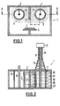
- FIG. 1 shows a processing space 1 in which a substrate 2 is located is a substrate carrier 3, is treated by means of plasma 4, 5.
- the plasma 4, 5 is generated here by means of microwaves from a gas which is supplied by gas feeds 6, 7 arrives in the processing chamber 1. A negative pressure prevails in this processing chamber 1.
- the microwaves, which is the gas entering the processing chamber 1 convert into plasma, are via electrically conductive rods 8, 9, which are outside the Processing chamber 1 are connected to microwave generators in the processing chamber 1 introduced.
- These electrically conductive rods 8, 9 are each one Surround quartz tube 10, 11. Microwaves emerge from the bars 8, 9, which the Pass through quartz tubes 10, 11 and excite plasma 4, 5 outside the quartz tubes.
- a partition is located between the two adjacent quartz tubes 10, 11 12 made of electrically conductive material.
- This partition 12 is perpendicular to the plane, which is stretched between the bars 8, 9. It is on a wall of the housing 1 attached and is about the size of the diameter of one of the quartz tubes 10, 11.
- the partition 12 can also Provide passage openings, d. H. be designed as a perforated plate. In this way is a gas or plasma passage through the partition 12 possible, which the training homogeneous plasma fields easier.
- a gas is introduced into the chamber 1 via the gas feeds 6, 7, where it passes through the microwaves are converted into a plasma.
- the distance a between the outside an electrically conductive rod 8, 9 and the partition 12 is preferably a quarter of the wavelength of the microwave emanating from bars 8, 9.
- the processing chamber 1 is usually a vacuum chamber, in which a process gas or several process gases can be entered. By means of microwaves these process gases ionize and thus form a plasma from which ions form on the Precipitate substrate 2.
- the substrate is advantageously negative Potential.
- tubes 10, 11 are preferably made of quartz, other microwave-permeable ones can also be used Materials are used, for example ceramic or Teflon.
- the processing chamber 1 is shown again in a section A-A.
- the substrate 2 and the substrate carrier 3 as well as the conductive rods 8, 9, which are surrounded by the quartz tubes 10, 11.
- a Microwave generator 13 - for example, a coaxial magnetron - to recognize the communicates with a coaxial waveguide 14, the central part of which is an extension of the rod 9 represents.
- the wave running in the coaxial waveguide 14 becomes with the help of a funnel 15 to the conductive rod 9, which acts as a surface waveguide serves, adapted.
- the fields created on the rod 9 are designated 16 to 20 and symbolize Goubau-Harms surface waves.
- rod-shaped microwave radiator shown in FIGS. 1 and 2 can other emitters can also be provided if they produce a homogeneous one Plasma is possible.
- dielectric tube or jacket radiators can be used also belong to the surface wave antennas. Also dielectric rod or Stick radiators or two-wire waveguides are possible.
- Waveguides are used, e.g. B. a slotted coaxial line, a dielectric Image line or a slotted waveguide.
- the quartz tubes 10, 11 are not themselves waveguides, but can be indirect lead to a waveguide, because the directly on the outside of the quartz tubes 10, 11 Ionization is most pronounced.
- the highly ionized plasma particles in immediate Proximity to the outside of the quartz tubes 10, 11 can hereby be like an electrical one Conductors and thus act like the sheath of a coaxial cable.
- a separate microwave generator 13 is provided for a rod 9. It it is also possible to use only one microwave generator for several rods, as shown for example in DE 196 28 949 A1, or microwave generators to be arranged on both sides of a rod and to this from two sides Food.
- the strength of the microwaves decreases with increasing Distance from the microwave generator 13 more and more. Now becomes a mirror image to the microwave generator 13, a second microwave generator at the other end connected to the rod 9, the drop in intensity of the microwaves can be compensated become.
- a quartz tube 10, 11 when microwaves are fed in from one side can be done in different ways.
- the quartz tube 10, 11 on the end opposite the microwave generator 13 like a test tube
- a reflective metal wall can also be the finishing touch form. With a suitable size of the quartz tubes 10, 11 and the microwave wavelengths a kind of resonator can thereby be formed.
- Fig. 3 shows a processing chamber 1 with the same electrically conductive Bars 8, 9 and equipped with the same quartz tubes 10, 11 as the processing chamber 1 of FIG. 1.
- the quartz tubes 10, 11 are in this embodiment however, embedded in an electrically conductive block 42 in such a way that it Block 42 does not surround only that part of the quartz tubes 10, 11 that is through the Opening angle W is designated.
- This opening angle W is preferably between 10 and 90 degrees. With this variant, too, care should be taken that the distance a between the outer circumference of the respective rod 8, 9 and the subsequent one Block 42 a quarter of the wavelength of the emitted microwave corresponds.
- the middle region 21 of the block 42 takes over in this embodiment the function of the partition 12 in FIGS. 1 and 2.
- the advantage of this embodiment is that even with longer structures, d. H. Structures that extend far into the plane of the drawing are largely one homogeneous distribution of the plasma is achieved along these structures. Moreover the gas entering through the inlets 6, 7 must flow closely around the quartz tubes 10, 11, since only a small cylindrical gap 23, 24 between the quartz tubes and the Block 42 is provided. The choice of the width of the columns 23, 24 determines whether a narrowly delimited, very dense plasma is burning within the columns 23, 24 or whether the formation of the plasma is suppressed. In the latter case, it is limited the plasma to the opening angle W.
- FIG. 4 shows a further variant of the invention, in particular in the high-rate coating of large-area molded parts is used.
- this variant it is possible to use a given plasma source with different shaped parts Size and shape to achieve short-term and homogeneous treatment, for example, to adapt a coating.
- Block 42 is now shown as two symmetrical blocks 25, 26, which by a Suction hole 27 are separated.
- Plasma guide parts 28 to 31 are also flanged to the blocks 25, 26.
- the lateral plasma guide parts 28 and 31 are provided with gas guide channels 32, 33, those with corresponding gas routing channels 34, 35 in blocks 25, 26 in Connect.
- the gas guide channels 36, 37, the Plasma guide parts 29, 30 correspond to the corresponding channels 38, 39 in the blocks 25, 26 are connected.
- a first gas via the gas guide channels 6, 7 and a second gas the gas guide channels 38, 35 fed a third gas.
- At 40 is a dividing line between the blocks 25, 26 and the plasma guide parts Designated 28 to 31.
- the plasma guide parts 28 to 31 are on this Separation line 40 releasably connected to the blocks 25, 26, for example by means of screws, which are not shown in FIG. 4.
- the suction holes 27, 52, 53 and Gas guide channels 32, 33, 34, 35, 36, 37, 38, 39 must be designed so that does not form plasma in them. It is crucial that the diameter of Suction hole and gas channels are sufficiently small at a given pressure.
- the plasma guide parts form here 28 to 31 nozzles 50, 51 with funnel-shaped opening.
- the Distribution and the jet characteristic of the nozzles 50, 51 and thus the inflow speed the starting substances in the processing chamber 1 can be changed.
- a heater not shown here, is accommodated in the blocks 25, 26, it can the plasma guide parts 28 to 31 are also heated, since these have a good thermal Have contact with blocks 34, 35.
- the heating of the blocks 25, 26 can by heating spirals, by radiant heat, by induction heating or by other means Way.
- the heating of the blocks 25, 26 and thus the plasma guide parts is in the introduction of certain starting substances through the gas guide channels 34, 6, 38, 39, 7, 35 required because these substances are at a certain temperature must be heated to show the desired reactions in the plasma room.
- With the suction channels 27, 52, 53 and a pump 60 it is possible to produce reaction products to suck out of the processing chamber 1 to the outside.
- FIG. 5 shows a variant of FIG. 4, in which the molded parts which form the substrate 55, are held by supports 56, 57 which are formed that the gas space between the quartz tubes 10, 11 and the surface of the substrate 55 from the rest of the processing chamber 1, z. B. below the substrate 55 or located on the right and left of the supports 56, 57.
- This Apertures 56 to 59 - which does not appear from FIG. 5 - do not have to be as long as the quartz tubes 10, 11, but shorter, so that they face only parts of the plasma hide the rest of the processing chamber from nozzles 50, 51 is coming.
- the rods 8, 9 shown in the embodiments of FIGS. 1 to 5 can be solid or be hollow. If they are hollow, a cooling liquid can flow through the cavity.
Landscapes
- Physics & Mathematics (AREA)
- Engineering & Computer Science (AREA)
- Plasma & Fusion (AREA)
- Chemical & Material Sciences (AREA)
- Analytical Chemistry (AREA)
- Chemical Vapour Deposition (AREA)
- Plasma Technology (AREA)
- Physical Or Chemical Processes And Apparatus (AREA)
- Electron Sources, Ion Sources (AREA)
Applications Claiming Priority (2)
| Application Number | Priority Date | Filing Date | Title |
|---|---|---|---|
| DE19928876 | 1999-06-24 | ||
| DE1999128876 DE19928876A1 (de) | 1999-06-24 | 1999-06-24 | Vorrichtung zur lokalen Erzeugung eines Plasmas in einer Behandlungskammer durch Mikrowellenanregung |
Publications (2)
| Publication Number | Publication Date |
|---|---|
| EP1063678A2 true EP1063678A2 (fr) | 2000-12-27 |
| EP1063678A3 EP1063678A3 (fr) | 2004-01-07 |
Family
ID=7912336
Family Applications (1)
| Application Number | Title | Priority Date | Filing Date |
|---|---|---|---|
| EP00112949A Withdrawn EP1063678A3 (fr) | 1999-06-24 | 2000-06-20 | Dispositif de production d'un plasma excité par microondes dans une cavité |
Country Status (3)
| Country | Link |
|---|---|
| EP (1) | EP1063678A3 (fr) |
| JP (1) | JP2001058127A (fr) |
| DE (1) | DE19928876A1 (fr) |
Cited By (5)
| Publication number | Priority date | Publication date | Assignee | Title |
|---|---|---|---|---|
| WO2008046553A1 (fr) * | 2006-10-16 | 2008-04-24 | Iplas Innovative Plasma Systems Gmbh | Dispositif et procédé de production locale de plasmas de micro-ondes |
| WO2011064084A1 (fr) * | 2009-11-11 | 2011-06-03 | Roth & Rau Muegge Gmbh | Dispositif de production de plasma à l'aide de micro-ondes |
| DE102010043940A1 (de) * | 2010-11-15 | 2012-05-16 | Forschungsverbund Berlin E.V. | Mikrowellen-ICP-Resonator |
| WO2019233750A1 (fr) * | 2018-06-06 | 2019-12-12 | Meyer Burger (Germany) Gmbh | Source de plasma à micro-ondes linéaire comportant des espaces à plasma séparés |
| WO2019233703A1 (fr) * | 2018-06-06 | 2019-12-12 | Meyer Burger (Germany) Gmbh | Dispositif de traitement au plasma comprenant une source de plasma à micro-ondes linéaire et un dispositif de conduite de gaz |
Families Citing this family (10)
| Publication number | Priority date | Publication date | Assignee | Title |
|---|---|---|---|---|
| US7498066B2 (en) | 2002-05-08 | 2009-03-03 | Btu International Inc. | Plasma-assisted enhanced coating |
| US7638727B2 (en) | 2002-05-08 | 2009-12-29 | Btu International Inc. | Plasma-assisted heat treatment |
| US7497922B2 (en) | 2002-05-08 | 2009-03-03 | Btu International, Inc. | Plasma-assisted gas production |
| US7560657B2 (en) | 2002-05-08 | 2009-07-14 | Btu International Inc. | Plasma-assisted processing in a manufacturing line |
| US7432470B2 (en) | 2002-05-08 | 2008-10-07 | Btu International, Inc. | Surface cleaning and sterilization |
| US7494904B2 (en) | 2002-05-08 | 2009-02-24 | Btu International, Inc. | Plasma-assisted doping |
| EP1501631A4 (fr) | 2002-05-08 | 2009-07-22 | Btu Int | Realisation au plasma de structures au carbone |
| US7445817B2 (en) | 2002-05-08 | 2008-11-04 | Btu International Inc. | Plasma-assisted formation of carbon structures |
| US7465362B2 (en) | 2002-05-08 | 2008-12-16 | Btu International, Inc. | Plasma-assisted nitrogen surface-treatment |
| US7189940B2 (en) | 2002-12-04 | 2007-03-13 | Btu International Inc. | Plasma-assisted melting |
Family Cites Families (9)
| Publication number | Priority date | Publication date | Assignee | Title |
|---|---|---|---|---|
| NZ220550A (en) * | 1986-06-05 | 1990-10-26 | Nearctic Research Centre Austr | Microwave drier cavity: configuration maximises energy in drying zone while minimising energy reflected back to source |
| US4893584A (en) * | 1988-03-29 | 1990-01-16 | Energy Conversion Devices, Inc. | Large area microwave plasma apparatus |
| US5202095A (en) * | 1988-12-27 | 1993-04-13 | Matsushita Electric Industrial Co., Ltd. | Microwave plasma processor |
| DE4136297A1 (de) * | 1991-11-04 | 1993-05-06 | Plasma Electronic Gmbh, 7024 Filderstadt, De | Vorrichtung zur lokalen erzeugung eines plasmas in einer behandlungskammer mittels mikrowellenanregung |
| DE4336830A1 (de) * | 1993-10-28 | 1995-05-04 | Leybold Ag | Plasma-Zerstäubungsanlage mit Mikrowellenunterstützung |
| DE19503205C1 (de) * | 1995-02-02 | 1996-07-11 | Muegge Electronic Gmbh | Vorrichtung zur Erzeugung von Plasma |
| DE19628949B4 (de) * | 1995-02-02 | 2008-12-04 | Muegge Electronic Gmbh | Vorrichtung zur Erzeugung von Plasma |
| DE19540543A1 (de) * | 1995-10-31 | 1997-05-07 | Leybold Ag | Vorrichtung zum Beschichten eines Substrats mit Hilfe des Chemical-Vapor-Deposition-Verfahrens |
| DE19608949A1 (de) * | 1996-03-08 | 1997-09-11 | Ralf Dr Spitzl | Vorrichtung zur Erzeugung von leistungsfähigen Mikrowellenplasmen |
-
1999
- 1999-06-24 DE DE1999128876 patent/DE19928876A1/de not_active Withdrawn
-
2000
- 2000-06-20 EP EP00112949A patent/EP1063678A3/fr not_active Withdrawn
- 2000-06-23 JP JP2000189657A patent/JP2001058127A/ja not_active Withdrawn
Cited By (10)
| Publication number | Priority date | Publication date | Assignee | Title |
|---|---|---|---|---|
| WO2008046553A1 (fr) * | 2006-10-16 | 2008-04-24 | Iplas Innovative Plasma Systems Gmbh | Dispositif et procédé de production locale de plasmas de micro-ondes |
| WO2011064084A1 (fr) * | 2009-11-11 | 2011-06-03 | Roth & Rau Muegge Gmbh | Dispositif de production de plasma à l'aide de micro-ondes |
| CN103003913A (zh) * | 2009-11-11 | 2013-03-27 | 米格有限责任公司 | 用于借助微波生成等离子体的装置 |
| CN103003913B (zh) * | 2009-11-11 | 2016-02-24 | 米格有限责任公司 | 用于借助微波生成等离子体的装置 |
| US10290471B2 (en) | 2009-11-11 | 2019-05-14 | Muegge Gmbh | Device for generating plasma by means of microwaves |
| DE102009044496B4 (de) | 2009-11-11 | 2023-11-02 | Muegge Gmbh | Vorrichtung zur Erzeugung von Plasma mittels Mikrowellen |
| DE102010043940A1 (de) * | 2010-11-15 | 2012-05-16 | Forschungsverbund Berlin E.V. | Mikrowellen-ICP-Resonator |
| DE102010043940B4 (de) * | 2010-11-15 | 2012-08-30 | Forschungsverbund Berlin E.V. | Mikrowellen-ICP-Resonator |
| WO2019233750A1 (fr) * | 2018-06-06 | 2019-12-12 | Meyer Burger (Germany) Gmbh | Source de plasma à micro-ondes linéaire comportant des espaces à plasma séparés |
| WO2019233703A1 (fr) * | 2018-06-06 | 2019-12-12 | Meyer Burger (Germany) Gmbh | Dispositif de traitement au plasma comprenant une source de plasma à micro-ondes linéaire et un dispositif de conduite de gaz |
Also Published As
| Publication number | Publication date |
|---|---|
| JP2001058127A (ja) | 2001-03-06 |
| EP1063678A3 (fr) | 2004-01-07 |
| DE19928876A1 (de) | 2000-12-28 |
Similar Documents
| Publication | Publication Date | Title |
|---|---|---|
| DE19503205C1 (de) | Vorrichtung zur Erzeugung von Plasma | |
| EP1063678A2 (fr) | Dispositif de production d'un plasma excité par microondes dans une cavité | |
| EP2839500B1 (fr) | Dispositif générateur de plasma micro-ondes et procédé pour le faire fonctionner | |
| DE69426463T2 (de) | Mikrowellenplasmareaktor | |
| EP0593931B1 (fr) | Dispositif de production de plasmas micro-ondes | |
| DE4136297A1 (de) | Vorrichtung zur lokalen erzeugung eines plasmas in einer behandlungskammer mittels mikrowellenanregung | |
| EP0486943B1 (fr) | Dispositif pour l'excitation d'un champ à micro-ondes uniforme | |
| DE4319717A1 (de) | Vorrichtung zum Erzeugen planaren Niedrigdruckplasmas unter Verwendung einer Spule mit deren Achse parallel zu der Oberfläche eines Koppelfensters | |
| DE2504860B2 (de) | Mikrowellen-Heizvorrichtung | |
| DE4028525A1 (de) | Mikrowellen-plasmaquellenvorrichtung | |
| DE3111305A1 (de) | Mikrowellen-entladungs-ionenquelle | |
| WO2019141337A1 (fr) | Dispositif à plasma micro-onde | |
| WO1998054748A1 (fr) | Dispositif pour la production de plasma | |
| DE19801366B4 (de) | Vorrichtung zur Erzeugung von Plasma | |
| DE2441767A1 (de) | Plasmaquelle grossen querschnittes und ionenbeschleuniger | |
| DE4100462C2 (fr) | ||
| DE10341239B4 (de) | ECR-Plasmaquelle mit linearer Plasmaaustrittsöffnung | |
| DE69907687T2 (de) | Plasmabearbeitungsvorrichtung mit elektrisch leitender Wand | |
| WO2011064084A1 (fr) | Dispositif de production de plasma à l'aide de micro-ondes | |
| EP4154292B1 (fr) | Dispositif de traitement par micro-ondes | |
| DE4431785A1 (de) | Plasmagerät | |
| DE3242638A1 (de) | Wellenleiter fuer hochfrequenzuebertragung | |
| DD300723A7 (de) | Mikrowellen - Plasmaquelle | |
| DE69830083T2 (de) | Elektromagnetische strahlung expositionskammer für verbesserte heizung | |
| DE10358329B4 (de) | Vorrichtung zur Erzeugung angeregter und/oder ionisierter Teilchen in einem Plasma und Verfahren zur Erzeugung ionisierter Teilchen |
Legal Events
| Date | Code | Title | Description |
|---|---|---|---|
| PUAI | Public reference made under article 153(3) epc to a published international application that has entered the european phase |
Free format text: ORIGINAL CODE: 0009012 |
|
| AK | Designated contracting states |
Kind code of ref document: A2 Designated state(s): AT BE CH CY DE DK ES FI FR GB GR IE IT LI LU MC NL PT SE |
|
| AX | Request for extension of the european patent |
Free format text: AL;LT;LV;MK;RO;SI |
|
| RAP1 | Party data changed (applicant data changed or rights of an application transferred) |
Owner name: LEYBOLD OPTICS GMBH |
|
| PUAL | Search report despatched |
Free format text: ORIGINAL CODE: 0009013 |
|
| AK | Designated contracting states |
Kind code of ref document: A3 Designated state(s): AT BE CH CY DE DK ES FI FR GB GR IE IT LI LU MC NL PT SE |
|
| AX | Request for extension of the european patent |
Extension state: AL LT LV MK RO SI |
|
| 17P | Request for examination filed |
Effective date: 20040110 |
|
| AKX | Designation fees paid |
Designated state(s): CH DE FR GB IT LI |
|
| STAA | Information on the status of an ep patent application or granted ep patent |
Free format text: STATUS: THE APPLICATION IS DEEMED TO BE WITHDRAWN |
|
| 18D | Application deemed to be withdrawn |
Effective date: 20070101 |