EP1063754A2 - Transversalflussmaschine - Google Patents
Transversalflussmaschine Download PDFInfo
- Publication number
- EP1063754A2 EP1063754A2 EP00890195A EP00890195A EP1063754A2 EP 1063754 A2 EP1063754 A2 EP 1063754A2 EP 00890195 A EP00890195 A EP 00890195A EP 00890195 A EP00890195 A EP 00890195A EP 1063754 A2 EP1063754 A2 EP 1063754A2
- Authority
- EP
- European Patent Office
- Prior art keywords
- pole elements
- stator
- machine
- machine according
- pole
- Prior art date
- Legal status (The legal status is an assumption and is not a legal conclusion. Google has not performed a legal analysis and makes no representation as to the accuracy of the status listed.)
- Granted
Links
- 230000004907 flux Effects 0.000 title claims description 56
- 239000000463 material Substances 0.000 claims abstract description 47
- 230000015572 biosynthetic process Effects 0.000 claims description 8
- 238000005755 formation reaction Methods 0.000 claims description 8
- 238000003475 lamination Methods 0.000 claims description 8
- 238000004804 winding Methods 0.000 claims description 6
- 238000013016 damping Methods 0.000 claims description 4
- 239000004020 conductor Substances 0.000 claims description 3
- 239000013013 elastic material Substances 0.000 claims description 2
- XEEYBQQBJWHFJM-UHFFFAOYSA-N Iron Chemical compound [Fe] XEEYBQQBJWHFJM-UHFFFAOYSA-N 0.000 description 28
- 229910052742 iron Inorganic materials 0.000 description 14
- 239000002184 metal Substances 0.000 description 6
- 229910052751 metal Inorganic materials 0.000 description 6
- 230000009467 reduction Effects 0.000 description 5
- 239000000696 magnetic material Substances 0.000 description 3
- 238000004519 manufacturing process Methods 0.000 description 3
- PXHVJJICTQNCMI-UHFFFAOYSA-N Nickel Chemical compound [Ni] PXHVJJICTQNCMI-UHFFFAOYSA-N 0.000 description 2
- 230000000295 complement effect Effects 0.000 description 2
- 230000006698 induction Effects 0.000 description 2
- 238000010030 laminating Methods 0.000 description 2
- 230000005415 magnetization Effects 0.000 description 2
- 230000035699 permeability Effects 0.000 description 2
- 238000001266 bandaging Methods 0.000 description 1
- 230000008033 biological extinction Effects 0.000 description 1
- 238000000576 coating method Methods 0.000 description 1
- 229910017052 cobalt Inorganic materials 0.000 description 1
- 239000010941 cobalt Substances 0.000 description 1
- GUTLYIVDDKVIGB-UHFFFAOYSA-N cobalt atom Chemical compound [Co] GUTLYIVDDKVIGB-UHFFFAOYSA-N 0.000 description 1
- 238000006073 displacement reaction Methods 0.000 description 1
- 238000002955 isolation Methods 0.000 description 1
- 238000013507 mapping Methods 0.000 description 1
- 229910052759 nickel Inorganic materials 0.000 description 1
- 239000002245 particle Substances 0.000 description 1
- 238000004080 punching Methods 0.000 description 1
- 238000005245 sintering Methods 0.000 description 1
- 230000007704 transition Effects 0.000 description 1
Images


Classifications
-
- H—ELECTRICITY
- H02—GENERATION; CONVERSION OR DISTRIBUTION OF ELECTRIC POWER
- H02K—DYNAMO-ELECTRIC MACHINES
- H02K21/00—Synchronous motors having permanent magnets; Synchronous generators having permanent magnets
- H02K21/12—Synchronous motors having permanent magnets; Synchronous generators having permanent magnets with stationary armatures and rotating magnets
- H02K21/125—Synchronous motors having permanent magnets; Synchronous generators having permanent magnets with stationary armatures and rotating magnets having an annular armature coil
-
- H—ELECTRICITY
- H02—GENERATION; CONVERSION OR DISTRIBUTION OF ELECTRIC POWER
- H02K—DYNAMO-ELECTRIC MACHINES
- H02K1/00—Details of the magnetic circuit
- H02K1/06—Details of the magnetic circuit characterised by the shape, form or construction
- H02K1/12—Stationary parts of the magnetic circuit
- H02K1/14—Stator cores with salient poles
- H02K1/145—Stator cores with salient poles having an annular coil, e.g. of the claw-pole type
-
- H—ELECTRICITY
- H02—GENERATION; CONVERSION OR DISTRIBUTION OF ELECTRIC POWER
- H02K—DYNAMO-ELECTRIC MACHINES
- H02K21/00—Synchronous motors having permanent magnets; Synchronous generators having permanent magnets
- H02K21/12—Synchronous motors having permanent magnets; Synchronous generators having permanent magnets with stationary armatures and rotating magnets
- H02K21/22—Synchronous motors having permanent magnets; Synchronous generators having permanent magnets with stationary armatures and rotating magnets with magnets rotating around the armatures, e.g. flywheel magnetos
- H02K21/227—Synchronous motors having permanent magnets; Synchronous generators having permanent magnets with stationary armatures and rotating magnets with magnets rotating around the armatures, e.g. flywheel magnetos having an annular armature coil
-
- H—ELECTRICITY
- H02—GENERATION; CONVERSION OR DISTRIBUTION OF ELECTRIC POWER
- H02K—DYNAMO-ELECTRIC MACHINES
- H02K2201/00—Specific aspects not provided for in the other groups of this subclass relating to the magnetic circuits
- H02K2201/12—Transversal flux machines
-
- H—ELECTRICITY
- H02—GENERATION; CONVERSION OR DISTRIBUTION OF ELECTRIC POWER
- H02K—DYNAMO-ELECTRIC MACHINES
- H02K5/00—Casings; Enclosures; Supports
- H02K5/24—Casings; Enclosures; Supports specially adapted for suppression or reduction of noise or vibrations
Definitions
- the invention relates to a transverse flux machine Permanent magnets arranged over the circumference of the rotor of the machine in a number corresponding to the number of poles of the machine and if necessary arranged between the permanent magnets Flux guides made of magnetically conductive material, and with pole elements arranged over the circumference of the stator of the machine to hold windings to generate a magnetic Flux and to guide the magnetic flux.
- Transverse flux machines are characterized by a special, three-dimensional magnetic flux, whereby in contrast to conventional electrical machines magnetic Flow lines also in the transverse direction, i.e. parallel run to the axis of rotation of the machine, which also gives the name of these machines.
- transverse flux machines With transverse flux machines generates a magnetic field using ring windings on the stator, which has corresponding pole elements over the air gap runs to the rotor and there with the help of permanent magnets and at most, river guide pieces concentrated and in their direction is directed.
- the pole elements on the stator are usually made of soft magnetic material. Laminates are often used Sheets with a lamination direction parallel to the axis of rotation the machine used.
- the pole elements usually have a U shape single-phase transverse flux machines or corresponding comb shape in multi-phase transverse flux machines, with between the legs of the pole elements pointing in the direction of the rotor the ring winding is arranged.
- the pole elements of the machine can be divided.
- Laminated sheets point in the direction of the plane of the sheets very good magnetic conductivity while normal too the level of the sheets has a very poor magnetic conductivity demonstrate. Accordingly, the three-dimensional course of the magnetic flux in transverse flux machines in those Areas where the magnetic field lines are normal Lamination direction run, with relatively high iron losses to count.
- the aim of the present invention is to reduce the magnetic Losses in the stator, so that the power yield and the efficiency of the machine can be increased.
- the magnetic Losses in the stator fall in particular the iron losses as well as the losses caused by stray fields.
- the object of the invention is achieved in that at least part of the pole elements of the stator of the machine magnetically isotropic material.
- Magnetically isotropic materials have the same magnetic properties in all directions, in contrast to laminated sheets, which are only available in Have preferred properties in the direction of the sheet metal planes. By using such magnetically isotropic materials the losses can be reduced accordingly.
- the stator of the machine made of magnetically isotropic material, in which the magnetic flux deviates from the radial direction. If laminated sheets are used, this runs Lamellar plane usually in the radial direction. Therefore should particularly be those areas where the magnetic flux normal to the radial direction or the lamination levels stands, i.e. transversal, i.e. parallel to the axis of rotation of the machine or tangential to the axis of rotation of the machine, made of magnetic isotropic material. This allows in those areas that are usually very poor magnetic Have conductivity when using laminated cores that Losses can be further reduced and thus the power yield the machine can be increased.
- Pole elements of the stator can be made of magnetic sintered material consist. Although these materials are currently even more expensive than laminated sheets, but the production is especially more complex shapes, significantly sintered easier.
- the sintered materials consist of iron, nickel or cobalt particles, which with suitable coatings are provided and with each other by suitable binding materials get connected.
- At least the poles of the substantially normal to the axis of rotation the machine standing leg of the pole elements made of magnetic isotropic material. Use in these areas also Magnetic isotropic materials have advantages because of these Areas the flow direction is three-dimensional and thus losses are to be expected from stray fields.
- the pole elements of the stator of the machine made of laminated sheets, the lamination plane being substantially normal to Axis of rotation of the machine is.
- the direction of the rotor of the machine facing poles of the pole elements at their ends for formation be bent by pole pieces.
- the sheets are one Sheet packets bent in the same direction while the sheets of the next adjacent laminated core is bent in the opposite direction are.
- pole shoes which are Increase the torque-generating surface and thus an increase in torque.
- the magnetic Flow through the appropriate design of the laminated core be directed in a preferred direction and the Leakage flux to the outside can be reduced.
- the laminated sheets combined to sheet packages, which against each other, essentially around a pole pitch or odd multiples of the pole pitch are twisted.
- the pole pitch is defined by the ratio of the effective scope between rotor and stator of the machine to the number of poles.
- Parts of the stator are made of magnetically isotropic Material existing parts of the pole elements of the stator formations on, which in correspondingly complementary designs the adjacent parts of the stator can intervene. This allows in particular a tool-free and connection without additional aids can be achieved. Such forms can be barb-shaped, so that a shift the parts can be prevented from each other.
- Sintered materials in particular can be of almost any design the pole elements can be achieved, which in use of sheet metal would not be possible. Accordingly, according to one Another feature of the invention provided that the entire Pole elements of the stator consist of magnetically isotropic material. This can reduce costs compared to laminated variants be achieved.
- pole elements are made in several pieces, whereby the individual parts of the pole elements are designed to be complementary Formations are connected to each other, can be simple manufacture be achieved.
- pole elements are made in one piece can be assembled from a very common large number of individual parts existing transverse flux machines be made considerably easier.
- the legs and / or webs of the pole elements in the direction of the rotor diverge essentially wedge-shaped and in the direction the Pole converge.
- the legs result in a larger cross-sectional area, resulting in this Area the magnetic induction is reduced and thus the Iron losses can be reduced.
- the poles are tapered again, so that those on the rotor opposite permanent magnets through the poles not magnetic be closed briefly, which leads to a reduction or Extinction of the resulting torque would result.
- Damping inserts can be placed between the legs of the pole elements made of elastic material, such as rubber his. These bring a damping or reduction in mechanical stress due to vibrations between the individual Pole element parts with itself and also causes the necessary Isolation of the individual pole elements.
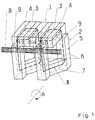
- FIG. 1 shows a Principle sketch of a part of a transverse flux machine for Explanation of the magnetic flux
- Fig. 2 the iron losses depending on the frequency and the magnetic permeability depending on the magnetic field strength for explanation the differences of magnetically isotropic material laminated sheets
- Fig. 3 shows an embodiment of the Pole elements of the stator of a transverse flux machine according to the invention in cross section
- Fig. 4a and 4b the design of the Poles of the laminated pole elements
- Fig. 5 the execution of the poles the pole elements in the form of magnetically isotropic material
- Fig. 7a and 7b two embodiments of the pole elements in Cross-section.
- Fig. 1 shows a three-dimensional section of a Transversal flux machine in the form of an external rotor (i.e. the rotating part of the machine is on the outside) for illustration of the magnetic flux.
- the outrunner are over the Scope of permanent magnets 3 in a number corresponding to the number of poles 2p of the machine and between the permanent magnets 3
- Flow guide pieces 4 made of magnetically conductive material.
- the axis of rotation of the machine is indicated by reference symbol A.
- the permanent magnets 3 are magnetized in the tangential direction.
- the permanent magnet 3 By marking the north pole N and south pole S the permanent magnet 3 illustrates the direction of magnetization.
- Magnetically conductive are on the stator 2 of the machine Pole elements 5 arranged, which are usually U-shaped or Comb shape in corresponding multi-phase transverse flux machines available.
- the web 7 runs between the legs 6 of the pole elements 5 is the winding 8, which is usually in the form of a ring winding is present, which is the magnetic field in the stator evokes.
- the magnetic flux ⁇ runs as in the illustration indicated in a three-dimensional form, whereby partially radially over the legs 6 of the pole elements 5 and transversely across the web 7 of the pole elements.
- Pole elements 5 made of laminated metal sheets are in the direction of Sheets have a high magnetic conductivity and therefore low Loss of iron causes, but normally you get a very low magnetic conductivity.
- the stray fields occur mainly between the pole elements 5 and on the poles 9 am Air gap between rotor 1 and stator 2.
- Fig. 2 shows the course of the iron losses depending the frequency for magnetic materials from sheet metal fins and made of sintered material.
- the top curve shows the iron losses for laminated sheet metal with a laminating direction transverse to the direction of the magnetic flux ⁇ , therefore the Iron losses relatively high.
- the bottom curve shows the iron losses for dynamo sheet with a lamination direction in Direction of the magnetic field lines. With such materials the iron losses are minimal.
- the losses with magnetically isotropic Materials such as are magnetic sintered materials independent of direction and are approximately between the size Losses for the two magnetization directions laminated sheets. Are the magnetic field lines only in on one level, the use of sheet metal is preferable. At the laminating direction is correct coincides with the field line level. However, with transverse flux machines, where the magnetic flux is not in one plane is the sum of the losses in sintered materials less.
- the mapping of the permeability ⁇ depending on the magnetic field strength H illustrates the properties of magnetic Sintered materials.
- Fig. 3 shows an embodiment of the pole elements 5 of the Stator 2, in which the parts of the pole elements 5, in which the magnetic flux transverse, i.e. parallel to the axis of rotation A runs, these are the webs 7 of the pole elements 5, made of magnetic Sintered material or magnetically isotropic material produced are.
- the parts of the pole elements 5, in which the magnetic flux ⁇ runs radially, that is the legs 6 of the Pole elements 5 can be made of soft magnetic material Lamination direction to be constructed normal to the axis of rotation A.
- FIG. 4a and 4b show an embodiment of the machine, in which the legs 6 of the pole elements 5 by laminated laminations are constructed, the poles 9 of the legs 6 of the pole elements 5 to enlarge the torque-generating surface are bent.
- a part can be used to make the machine easier to assemble the web 7 of the pole elements 5 also by laminated sheets be made so that the pole elements 5 of the stator 2 individual disks, as shown in Fig. 4a, are constructed.
- Fig. 5 shows an embodiment of the machine in which the Poles 9 are made of magnetically isotropic material.
- corresponding formations 10 can connect to the underlying Parts of the pole elements 5, which are the correct positioning of the poles 9 and a fixation, guaranteed in particular in the radial direction R.
- the pole elements 5 can also made entirely of magnetically isotropic material, in particular sintered material, be made. Especially in manufacturing almost any shape can be achieved by sintering, whereby the legs 6 of the pole elements 5 widen can be achieved, resulting in an increase in area, thus to a reduction in the magnetic induction B and to one Reduction of iron losses leads. Towards the end of the leg 6 of the Pole elements 5 must be tapered again, so that there is no magnetic short circuit on the rotor 1 arranged permanent magnets 3 and thus at all Torque generation is coming.
- the pole 9 Pole elements 5 grooves 11 are provided, which for Bandaging the arrangement when building the machine.
- Fig. 6b shows a variant in which the pole elements 5 of the entire machine made in one piece in the form of a ring are. Likewise, a certain number of pole elements 5 be made in one piece in the form of a ring segment and the entire machine is made up of some such ring segments become. In this case the individual parts are preferred provided with complementarily shaped formations 10, about the a tool-free connection possible without additional aids is. Such an embodiment is shown in Fig. 6c, at of the individual pole elements 5 with adjacent stator components and or or adjacent pole elements 5 are positively connected become.
- pole elements 5 damping inserts 12 for example made of rubber, arranged be used to isolate the pole elements 5 and to dampen or reduce the mechanical load by Vibrations between the individual pole elements 5 serve.
- the Pole shoe can also be constructed asymmetrically, as in Fig. 7b shown. This allows the magnetic flux to move in a preferred direction be directed. Since pole elements made of sintered material can take almost any shape is one Design relatively easy and inexpensive to achieve.
Landscapes
- Engineering & Computer Science (AREA)
- Power Engineering (AREA)
- Iron Core Of Rotating Electric Machines (AREA)
- Permanent Field Magnets Of Synchronous Machinery (AREA)
- Motorcycle And Bicycle Frame (AREA)
- Nonmetallic Welding Materials (AREA)
Abstract
Description
Claims (15)
- Transversalflussmaschine mit über den Umfang des Rotors (1) der Maschine angeordneten Permanentmagneten (3) in einer Anzahl entsprechend der Polzahl (2p) der Maschine und allenfalls zwischen den Permanentmagneten (3) angeordneten Flussleitstücken (4) aus magnetisch leitfähigem Material, und mit über den Umfang des Stators (2) der Maschine angeordneten Polelementen (5) zur Aufnahme von Wicklungen (8) zur Erzeugung eines magnetischen Flusses (Φ) und zur Leitung des magnetischen Flusses (Φ), dadurch gekennzeichnet, dass zumindest ein Teil der Polelemente (5) des Stators (2) der Maschine aus magnetisch isotropem Material besteht.
- Transversalflussmaschine nach Anspruch 1, dadurch gekennzeichnet, dass zumindest jene Teile der Polelemente (5) des Stators (2) der Maschine aus magnetisch isotropem Material bestehen, in welchen der magnetische Fluss (Φ) von der radialen Richtung (R) abweicht.
- Transversalflussmaschine nach Anspruch 1 oder 2, dadurch gekennzeichnet, dass die aus magnetisch isotropem Material bestehenden Teile der Polelemente (5) des Stators (2) aus magnetischem Sintermaterial bestehen.
- Transversalflussmaschine nach einem der Ansprüche 1 bis 3, dadurch gekennzeichnet, dass zumindest die im wesentlichen parallel zur Drehachse (A) der Maschine verlaufenden Stege (7) der Polelemente (5) aus magnetisch isotropem Material bestehen.
- Transversalflussmaschine nach einem der Ansprüche 1 bis 3, dadurch gekennzeichnet, dass zumindest die Pole (9) der im wesentlichen normal auf die Drehachse (A) der Maschine stehenden Schenkel (6) der Polelemente (5) aus magnetisch isotropem Material bestehen.
- Transversalflussmaschine nach einem der Ansprüche 1 bis 5, dadurch gekennzeichnet, dass ein Teil der Polelemente (5) des Stators (2) der Maschine aus lamellierten Blechen besteht, wobei die Lamellierungsebene im wesentlichen normal zur Drehachse (A) der Maschine steht.
- Transversalflussmaschine nach Anspruch 6, dadurch gekennzeichnet, dass die zum Rotor (1) der Maschine weisenden Schenkel (6) der Polelemente (5) sowie ein Teil der im wesentlichen parallel zur Drehachse (A) der Maschine verlaufenden Stege (7) der Polelemente (5) des Stators (2) durch lamellierte Bleche gebildet sind.
- Transversalflussmaschine nach Anspruch 7, dadurch gekennzeichnet, dass die in Richtung des Rotors (1) der Maschine weisenden Pole (9) der Polelemente (5) an deren Enden zur Bildung von Polschuhen gebogen sind.
- Transversalflussmaschine nach einem der Ansprüche 6 bis 8, dadurch gekennzeichnet, dass die lamellierten Bleche zu Blechpaketen zusammengefasst sind, welche gegeneinander im wesentlichen um eine Polteilung (τp) oder ungeradzahlige Vielfache der Polteilung (τp) verdreht sind, wobei die Polteilung (τp) definiert ist durch das Verhältnis des wirksamen Umfangs zwischen Rotor (1) und Stator (2) zur Polzahl (2p).
- Transversalflussmaschine nach einem der Ansprüche 1 bis 9, dadurch gekennzeichnet, dass die aus magnetisch isotropem Material bestehenden Teile der Polelemente (5) des Stators (2) Ausformungen (10) zur Positionierung und Fixierung an den benachbarten Teilen des Stators (2) aufweisen.
- Transversalflussmaschine nach einem der Ansprüche 1 bis 3, dadurch gekennzeichnet, dass die gesamten Polelemente (5) des Stators (2) aus magnetisch isotropem Material bestehen.
- Transversalflussmaschine nach Anspruch 11, dadurch gekennzeichnet, dass die Polelemente (5) des Stators (2) mehrstückig hergestellt sind, wobei die einzelnen Teile der Polelemente (5) über komplementär gestaltete Ausformungen (10) miteinander verbunden sind.
- Transversalflussmaschine nach Anspruch 11, dadurch gekennzeichnet, dass die Polelemente (5) des Stators (2) einstückig hergestellt sind.
- Transversalflussmaschine nach einem der Ansprüche 11 bis 13, dadurch gekennzeichnet, dass die Schenkel (6) und/oder Stege (7) der Polelemente (5) in Richtung des Rotors (1) im wesentlichen keilförmig auseinanderlaufen und in Richtung der Pole (9) zusammenlaufen.
- Transversalflussmaschine nach einem der Ansprüche 11 bis 14, dadurch gekennzeichnet, dass zwischen den Schenkeln (6) der Polelemente (5) Dämpfungseinlagen (12) aus elastischem Material, beispielsweise aus Gummi, angeordnet sind.
Applications Claiming Priority (2)
| Application Number | Priority Date | Filing Date | Title |
|---|---|---|---|
| AT0109899A AT504456A1 (de) | 1999-06-22 | 1999-06-22 | Transversalflussmaschine |
| AT109899 | 1999-06-22 |
Publications (3)
| Publication Number | Publication Date |
|---|---|
| EP1063754A2 true EP1063754A2 (de) | 2000-12-27 |
| EP1063754A3 EP1063754A3 (de) | 2003-11-05 |
| EP1063754B1 EP1063754B1 (de) | 2007-12-12 |
Family
ID=3506553
Family Applications (1)
| Application Number | Title | Priority Date | Filing Date |
|---|---|---|---|
| EP00890195A Expired - Lifetime EP1063754B1 (de) | 1999-06-22 | 2000-06-23 | Transversalflussmaschine |
Country Status (3)
| Country | Link |
|---|---|
| EP (1) | EP1063754B1 (de) |
| AT (2) | AT504456A1 (de) |
| DE (1) | DE50014837D1 (de) |
Cited By (21)
| Publication number | Priority date | Publication date | Assignee | Title |
|---|---|---|---|---|
| WO2003047067A3 (en) * | 2001-11-23 | 2003-08-21 | David Calley | Electrical machine |
| DE10240704A1 (de) * | 2002-09-04 | 2004-04-08 | Tirron-Elektronik Gmbh | Hochpolige Wechselstrommaschinen |
| WO2006126973A1 (de) * | 2005-05-26 | 2006-11-30 | Meier, Mojca | Der stator mit beiderseits klauenförmigen polen |
| DE102008012324A1 (de) | 2008-03-03 | 2009-09-17 | Continental Automotive Gmbh | Elektrische Maschine mit Summenanregung |
| US7605515B2 (en) | 2004-05-06 | 2009-10-20 | Gerard Koehler | Variable reluctance dynamo-electric rotary machine provided with united magnetic, electric and polarising circuits and method for production thereof |
| DE10262148B4 (de) * | 2002-09-04 | 2010-10-28 | Tirron-Elektronik Gmbh | Hochpoliger, mehrphasiger Wechselstrommotoren mit transversaler Flussführung |
| EP2493054A1 (de) * | 2011-02-25 | 2012-08-29 | Siemens Aktiengesellschaft | Mehrphasige Transversalflussmaschine mit geschrägten Rückschlusssegmenten |
| WO2012125790A2 (en) | 2011-03-15 | 2012-09-20 | Motor Excellence Llc | Transverse and/or commutated flux systems having laminated and powdered metal portions |
| EP2605367A1 (de) | 2011-12-12 | 2013-06-19 | Siemens Aktiengesellschaft | Transversalflussmaschine mit Halbach-Arrays |
| CN103326487A (zh) * | 2012-03-22 | 2013-09-25 | 通用汽车环球科技运作有限责任公司 | 转子组件内的分段转子 |
| WO2015128072A3 (de) * | 2014-02-27 | 2016-07-07 | Sew-Eurodrive Gmbh & Co. Kg | Transversalflussmaschine |
| EP2641316A4 (de) * | 2010-11-17 | 2017-03-22 | Motor Excellence, LLC | Quer- oder mischflusssysteme mit segmentierten statorlamellen |
| US9722479B2 (en) | 2012-08-03 | 2017-08-01 | Eocycle Technologies Inc. | Wind turbine comprising a transverse flux electrical machine |
| US9876401B2 (en) | 2012-10-17 | 2018-01-23 | Eocycle Technologies Inc. | Transverse flux electrical machine rotor |
| CN110829629A (zh) * | 2018-08-10 | 2020-02-21 | 广东威灵电机制造有限公司 | 电机定子和电机 |
| WO2022035940A1 (en) * | 2020-08-12 | 2022-02-17 | Electric Torque Machines, Inc. | Electric motor |
| WO2022165029A1 (en) * | 2021-01-29 | 2022-08-04 | Electric Torque Machines, Inc. | Electric motor having laminas-formed teeth |
| US11831222B2 (en) | 2020-09-24 | 2023-11-28 | Electric Torque Machines, Inc. | Marine propeller system with high torque drive |
| EP4285475A1 (de) * | 2021-01-29 | 2023-12-06 | Electric Torque Machines, Inc. | Elektromotor |
| US12424884B2 (en) | 2020-02-10 | 2025-09-23 | Graco Minnesota Inc. | Transverse flux electric machine |
| US12492781B2 (en) | 2021-12-17 | 2025-12-09 | Graco Minnesota Inc. | Grease inhibitor |
Families Citing this family (18)
| Publication number | Priority date | Publication date | Assignee | Title |
|---|---|---|---|---|
| WO2008141214A1 (en) | 2007-05-09 | 2008-11-20 | Motor Excellence, Llc. | Electrical output generating devices and driven electrical devices with reduced flux leakage using permanent magnet components, and methods of making and using the same |
| US7973446B2 (en) | 2007-05-09 | 2011-07-05 | Motor Excellence, Llc | Electrical devices having tape wound core laminate rotor or stator elements |
| ES2392288T3 (es) | 2008-03-15 | 2012-12-07 | Compound Disk Drives Gmbh | Accionamiento directo de baja inercia con alta densidad de potencia |
| EP2342803A2 (de) | 2008-11-03 | 2011-07-13 | Motor Excellence, LLC | Rotorentwürfe für ein quer- oder mischflusssystem |
| WO2011115632A1 (en) | 2010-03-15 | 2011-09-22 | Motor Excellence Llc | Transverse and/or commutated flux systems configured to provide reduced flux leakage, hysteresis loss reduction, and phase matching |
| WO2011115634A1 (en) | 2010-03-15 | 2011-09-22 | Motor Excellence Llc | Transverse and/or commutated flux systems having phase offset |
| WO2011115633A1 (en) | 2010-03-15 | 2011-09-22 | Motor Excellence Llc | Transverse and/or commutated flux system for electric bicycles |
| DE102010018145B4 (de) | 2010-04-24 | 2012-07-26 | Kolektor Group D.O.O. | Dynamoelektrische Maschine der Klauenpolbauart |
| DE102010018146A1 (de) | 2010-04-24 | 2011-10-27 | Kolektor Group D.O.O. | Mehrphasige dynamoelektrische Maschine der Klauenpolbauart |
| US8952590B2 (en) | 2010-11-17 | 2015-02-10 | Electric Torque Machines Inc | Transverse and/or commutated flux systems having laminated and powdered metal portions |
| US8854171B2 (en) | 2010-11-17 | 2014-10-07 | Electric Torque Machines Inc. | Transverse and/or commutated flux system coil concepts |
| US9559558B2 (en) | 2012-09-24 | 2017-01-31 | Eocycle Technologies Inc. | Modular transverse flux electrical machine assembly |
| DE102019215015A1 (de) | 2019-09-30 | 2021-04-01 | Rolls-Royce Deutschland Ltd & Co Kg | Transversalflussmaschine |
| US11827371B1 (en) | 2023-01-11 | 2023-11-28 | Rolls-Royce Deutschland Ltd & Co Kg | Electrical machines for aircraft power and propulsion systems |
| GB2627179A (en) | 2023-01-11 | 2024-08-21 | Rolls Royce Deutschland Ltd & Co Kg | Electrical machines for aircraft power and propulsion systems |
| GB2626145A (en) | 2023-01-11 | 2024-07-17 | Rolls Royce Deutschland Ltd & Co Kg | Electrical machines for aircraft power and propulsion systems |
| US11990805B1 (en) | 2023-01-11 | 2024-05-21 | Rolls-Royce Deutschland Ltd & Co Kg | Electrical machines for aircraft power and propulsion systems having a defined machine parameter based on a ratio between an active parts torque density and a power factor |
| US11824410B1 (en) | 2023-01-11 | 2023-11-21 | Rolls-Royce Deutschland Ltd & Co Kg | Electrical machines for aircraft power and propulsion systems |
Family Cites Families (4)
| Publication number | Priority date | Publication date | Assignee | Title |
|---|---|---|---|---|
| DE3705089A1 (de) * | 1987-02-13 | 1988-08-25 | Weh Herbert | Transversalflussmaschine in sammleranordnung |
| GB9516497D0 (en) * | 1995-08-11 | 1995-10-11 | Rolls Royce Power Eng | Electrical machine |
| DE19728172C2 (de) * | 1997-07-02 | 2001-03-29 | Wolfgang Hill | Elektrische Maschine mit weichmagnetischen Zähnen und Verfahren zu ihrer Herstellung |
| DE19833021A1 (de) * | 1998-07-23 | 2000-01-27 | Voith Turbo Kg | Statorbaueinheit für eine elektrische Maschine |
-
1999
- 1999-06-22 AT AT0109899A patent/AT504456A1/de not_active Application Discontinuation
-
2000
- 2000-06-23 DE DE50014837T patent/DE50014837D1/de not_active Expired - Lifetime
- 2000-06-23 AT AT00890195T patent/ATE381140T1/de active
- 2000-06-23 EP EP00890195A patent/EP1063754B1/de not_active Expired - Lifetime
Cited By (32)
| Publication number | Priority date | Publication date | Assignee | Title |
|---|---|---|---|---|
| US6664704B2 (en) * | 2001-11-23 | 2003-12-16 | David Gregory Calley | Electrical machine |
| US6924579B2 (en) * | 2001-11-23 | 2005-08-02 | David Calley | Electrical machine |
| WO2003047067A3 (en) * | 2001-11-23 | 2003-08-21 | David Calley | Electrical machine |
| DE10240704A1 (de) * | 2002-09-04 | 2004-04-08 | Tirron-Elektronik Gmbh | Hochpolige Wechselstrommaschinen |
| DE10240704B4 (de) * | 2002-09-04 | 2006-04-27 | Tirron-Elektronik Gmbh | Hochpolige, mehrphasige Wechselstrommaschine mit transversaler Flussführung |
| DE10262148B4 (de) * | 2002-09-04 | 2010-10-28 | Tirron-Elektronik Gmbh | Hochpoliger, mehrphasiger Wechselstrommotoren mit transversaler Flussführung |
| US7605515B2 (en) | 2004-05-06 | 2009-10-20 | Gerard Koehler | Variable reluctance dynamo-electric rotary machine provided with united magnetic, electric and polarising circuits and method for production thereof |
| WO2006126973A1 (de) * | 2005-05-26 | 2006-11-30 | Meier, Mojca | Der stator mit beiderseits klauenförmigen polen |
| DE102008012324A1 (de) | 2008-03-03 | 2009-09-17 | Continental Automotive Gmbh | Elektrische Maschine mit Summenanregung |
| EP2641316A4 (de) * | 2010-11-17 | 2017-03-22 | Motor Excellence, LLC | Quer- oder mischflusssysteme mit segmentierten statorlamellen |
| WO2012113654A3 (de) * | 2011-02-25 | 2013-08-15 | Siemens Aktiengesellschaft | Mehrphasige transversalflussmaschine mit geschrägten rückschlusssegmenten |
| EP2493054A1 (de) * | 2011-02-25 | 2012-08-29 | Siemens Aktiengesellschaft | Mehrphasige Transversalflussmaschine mit geschrägten Rückschlusssegmenten |
| EP2686939A4 (de) * | 2011-03-15 | 2014-10-29 | Electric Torque Machines Inc | Quer- und/oder mischflusssysteme mit laminierten und pulverförmigen metallteilen |
| WO2012125790A2 (en) | 2011-03-15 | 2012-09-20 | Motor Excellence Llc | Transverse and/or commutated flux systems having laminated and powdered metal portions |
| EP2605367A1 (de) | 2011-12-12 | 2013-06-19 | Siemens Aktiengesellschaft | Transversalflussmaschine mit Halbach-Arrays |
| WO2013087412A1 (de) | 2011-12-12 | 2013-06-20 | Siemens Aktiengesellschaft | Transversalflussmaschine mit halbach-arrays |
| CN103326487A (zh) * | 2012-03-22 | 2013-09-25 | 通用汽车环球科技运作有限责任公司 | 转子组件内的分段转子 |
| US20130249345A1 (en) * | 2012-03-22 | 2013-09-26 | GM Global Technology Operations LLC | Segmented rotor in a rotor assembly |
| US9722479B2 (en) | 2012-08-03 | 2017-08-01 | Eocycle Technologies Inc. | Wind turbine comprising a transverse flux electrical machine |
| US9755492B2 (en) | 2012-08-03 | 2017-09-05 | Eocycle Technologies Inc. | Rotatable transverse flux electrical machine |
| US9876401B2 (en) | 2012-10-17 | 2018-01-23 | Eocycle Technologies Inc. | Transverse flux electrical machine rotor |
| WO2015128072A3 (de) * | 2014-02-27 | 2016-07-07 | Sew-Eurodrive Gmbh & Co. Kg | Transversalflussmaschine |
| CN110829629A (zh) * | 2018-08-10 | 2020-02-21 | 广东威灵电机制造有限公司 | 电机定子和电机 |
| US12424884B2 (en) | 2020-02-10 | 2025-09-23 | Graco Minnesota Inc. | Transverse flux electric machine |
| WO2022035940A1 (en) * | 2020-08-12 | 2022-02-17 | Electric Torque Machines, Inc. | Electric motor |
| US12374976B2 (en) | 2020-08-12 | 2025-07-29 | Electric Torque Machines, Inc. | Electric motor |
| US11831222B2 (en) | 2020-09-24 | 2023-11-28 | Electric Torque Machines, Inc. | Marine propeller system with high torque drive |
| US12424903B2 (en) | 2020-09-24 | 2025-09-23 | Graco Minnesota Inc. | Marine propeller system with high torque drive |
| WO2022165029A1 (en) * | 2021-01-29 | 2022-08-04 | Electric Torque Machines, Inc. | Electric motor having laminas-formed teeth |
| EP4285475A1 (de) * | 2021-01-29 | 2023-12-06 | Electric Torque Machines, Inc. | Elektromotor |
| US12567774B2 (en) | 2021-01-29 | 2026-03-03 | Electric Torque Machines, Inc. | Electric motor |
| US12492781B2 (en) | 2021-12-17 | 2025-12-09 | Graco Minnesota Inc. | Grease inhibitor |
Also Published As
| Publication number | Publication date |
|---|---|
| EP1063754A3 (de) | 2003-11-05 |
| AT504456A1 (de) | 2008-05-15 |
| DE50014837D1 (de) | 2008-01-24 |
| EP1063754B1 (de) | 2007-12-12 |
| ATE381140T1 (de) | 2007-12-15 |
Similar Documents
| Publication | Publication Date | Title |
|---|---|---|
| EP1063754B1 (de) | Transversalflussmaschine | |
| DE102004036691B4 (de) | Rotor für eine rotierende Maschine eines Reluktanztyps | |
| DE69309444T2 (de) | Bürstenloser gleichstrommotor/-generator | |
| DE69903187T2 (de) | Drehende elektrische maschine mit neuer anordnung für dauermagneterregter läufer | |
| DE112015007131T5 (de) | Elektromotor und Klimaanlage | |
| WO2007144232A1 (de) | Ringspulenmotor | |
| DE102013000222B4 (de) | Elektromotor, umfasssend einen Eisenkern mit primären Zähnen und sekundären Zähnen | |
| EP1005136A1 (de) | Ein- oder mehrphasige Transversalflussmaschine | |
| DE102011118064A1 (de) | Läufer und motor | |
| DE102010024344A1 (de) | Gleichstrom-Maschine | |
| DE112009002090T5 (de) | Drehende eletrische Maschine | |
| DE102014101221A1 (de) | Rotor für einen Permanentmagnet-Motor, Verfahren zur Herstellung eines Rotors für einen Permanentmagnet-Motor sowie Permanentmagnet-Motor | |
| DE102012219003A1 (de) | Läuferanordnung für eine rotatorische elektrische Maschine | |
| DE102013200476A1 (de) | Permanenterregte Synchronmaschine mit einem Rotor mit Permanentmagneten und Verfahren zur Herstellung derartiger Maschinen bzw. Rotoren | |
| DE102017102242A1 (de) | Verwendung von magnetfeldern in elektromaschinen | |
| DE102015104445A1 (de) | Elektromotor mit polygonalem Ständer | |
| DE102005047771A1 (de) | Rotoranordnung für eine elektrische Maschine und Verfahren zum Herstellen der Rotoranordnung | |
| DE102016212022A1 (de) | Rotor | |
| DE102006000455A1 (de) | Innenpermanentmagnetrotor und Innenpermanentmagnetmotor | |
| EP2587636A2 (de) | Elektrische Maschine, insbesondere bürstenloser Torquemotor | |
| DE19900170A1 (de) | Permanentmagnetmotor | |
| DE102019214434A1 (de) | Rotor einer elektrischen Maschine | |
| DE102008022209A1 (de) | Wechselstrommotor | |
| EP2792055A1 (de) | Elektrische maschine | |
| DE102008041604A1 (de) | Rotor für eine elektrische Maschine mit reduziertem Rastmoment |
Legal Events
| Date | Code | Title | Description |
|---|---|---|---|
| PUAI | Public reference made under article 153(3) epc to a published international application that has entered the european phase |
Free format text: ORIGINAL CODE: 0009012 |
|
| AK | Designated contracting states |
Kind code of ref document: A2 Designated state(s): AT BE CH CY DE DK ES FI FR GB GR IE IT LI LU MC NL PT SE |
|
| AX | Request for extension of the european patent |
Free format text: AL;LT;LV;MK;RO;SI |
|
| RAP1 | Party data changed (applicant data changed or rights of an application transferred) |
Owner name: BOMBARDIER TRANSPORTATION GMBH |
|
| PUAL | Search report despatched |
Free format text: ORIGINAL CODE: 0009013 |
|
| AK | Designated contracting states |
Kind code of ref document: A3 Designated state(s): AT BE CH CY DE DK ES FI FR GB GR IE IT LI LU MC NL PT SE |
|
| AX | Request for extension of the european patent |
Extension state: AL LT LV MK RO SI |
|
| 17P | Request for examination filed |
Effective date: 20040403 |
|
| AKX | Designation fees paid |
Designated state(s): AT DE FR GB |
|
| 17Q | First examination report despatched |
Effective date: 20061204 |
|
| GRAP | Despatch of communication of intention to grant a patent |
Free format text: ORIGINAL CODE: EPIDOSNIGR1 |
|
| GRAS | Grant fee paid |
Free format text: ORIGINAL CODE: EPIDOSNIGR3 |
|
| GRAA | (expected) grant |
Free format text: ORIGINAL CODE: 0009210 |
|
| AK | Designated contracting states |
Kind code of ref document: B1 Designated state(s): AT DE FR GB |
|
| REG | Reference to a national code |
Ref country code: GB Ref legal event code: FG4D Free format text: NOT ENGLISH |
|
| RIN1 | Information on inventor provided before grant (corrected) |
Inventor name: SCHAEFER, UWE Inventor name: STOCKMAYER, MICHAEL Inventor name: HACKMANN, WILHELM Inventor name: GUENTENSPERGER, WALTER Inventor name: NEUDORFER, HARALD |
|
| REF | Corresponds to: |
Ref document number: 50014837 Country of ref document: DE Date of ref document: 20080124 Kind code of ref document: P |
|
| GBT | Gb: translation of ep patent filed (gb section 77(6)(a)/1977) |
Effective date: 20080227 |
|
| ET | Fr: translation filed | ||
| PLBE | No opposition filed within time limit |
Free format text: ORIGINAL CODE: 0009261 |
|
| STAA | Information on the status of an ep patent application or granted ep patent |
Free format text: STATUS: NO OPPOSITION FILED WITHIN TIME LIMIT |
|
| 26N | No opposition filed |
Effective date: 20080915 |
|
| PGFP | Annual fee paid to national office [announced via postgrant information from national office to epo] |
Ref country code: AT Payment date: 20120613 Year of fee payment: 13 |
|
| PGFP | Annual fee paid to national office [announced via postgrant information from national office to epo] |
Ref country code: DE Payment date: 20130620 Year of fee payment: 14 Ref country code: GB Payment date: 20130619 Year of fee payment: 14 |
|
| PGFP | Annual fee paid to national office [announced via postgrant information from national office to epo] |
Ref country code: FR Payment date: 20130703 Year of fee payment: 14 |
|
| REG | Reference to a national code |
Ref country code: DE Ref legal event code: R119 Ref document number: 50014837 Country of ref document: DE |
|
| REG | Reference to a national code |
Ref country code: AT Ref legal event code: MM01 Ref document number: 381140 Country of ref document: AT Kind code of ref document: T Effective date: 20140623 |
|
| GBPC | Gb: european patent ceased through non-payment of renewal fee |
Effective date: 20140623 |
|
| REG | Reference to a national code |
Ref country code: DE Ref legal event code: R119 Ref document number: 50014837 Country of ref document: DE Effective date: 20150101 |
|
| REG | Reference to a national code |
Ref country code: FR Ref legal event code: ST Effective date: 20150227 |
|
| PG25 | Lapsed in a contracting state [announced via postgrant information from national office to epo] |
Ref country code: DE Free format text: LAPSE BECAUSE OF NON-PAYMENT OF DUE FEES Effective date: 20150101 |
|
| PG25 | Lapsed in a contracting state [announced via postgrant information from national office to epo] |
Ref country code: GB Free format text: LAPSE BECAUSE OF NON-PAYMENT OF DUE FEES Effective date: 20140623 Ref country code: FR Free format text: LAPSE BECAUSE OF NON-PAYMENT OF DUE FEES Effective date: 20140630 Ref country code: AT Free format text: LAPSE BECAUSE OF NON-PAYMENT OF DUE FEES Effective date: 20140623 |