EP1063760A2 - Regelung für einen linearen Vibrationsmotor - Google Patents
Regelung für einen linearen Vibrationsmotor Download PDFInfo
- Publication number
- EP1063760A2 EP1063760A2 EP00112726A EP00112726A EP1063760A2 EP 1063760 A2 EP1063760 A2 EP 1063760A2 EP 00112726 A EP00112726 A EP 00112726A EP 00112726 A EP00112726 A EP 00112726A EP 1063760 A2 EP1063760 A2 EP 1063760A2
- Authority
- EP
- European Patent Office
- Prior art keywords
- period
- vibrator
- amplitude
- controller
- winding
- Prior art date
- Legal status (The legal status is an assumption and is not a legal conclusion. Google has not performed a legal analysis and makes no representation as to the accuracy of the status listed.)
- Granted
Links
- 238000004804 winding Methods 0.000 claims abstract description 49
- 238000006073 displacement reaction Methods 0.000 claims abstract description 16
- 238000001514 detection method Methods 0.000 claims abstract description 9
- 230000001133 acceleration Effects 0.000 abstract description 6
- 230000004048 modification Effects 0.000 description 2
- 238000012986 modification Methods 0.000 description 2
- 238000012544 monitoring process Methods 0.000 description 2
- 230000003213 activating effect Effects 0.000 description 1
- 238000004519 manufacturing process Methods 0.000 description 1
- 230000010355 oscillation Effects 0.000 description 1
Images


Classifications
-
- H—ELECTRICITY
- H02—GENERATION; CONVERSION OR DISTRIBUTION OF ELECTRIC POWER
- H02P—CONTROL OR REGULATION OF ELECTRIC MOTORS, ELECTRIC GENERATORS OR DYNAMO-ELECTRIC CONVERTERS; CONTROLLING TRANSFORMERS, REACTORS OR CHOKE COILS
- H02P25/00—Arrangements or methods for the control of AC motors characterised by the kind of AC motor or by structural details
- H02P25/02—Arrangements or methods for the control of AC motors characterised by the kind of AC motor or by structural details characterised by the kind of motor
- H02P25/032—Reciprocating, oscillating or vibrating motors
Definitions
- the present invention is directed to a control system for a linear vibration motor, and more particularly to a system of driving a vibrator linearly with respect to a stator at a uniform amplitude.
- U.S. Patent No. 5,632,087 discloses a linear vibration motor composed of a stator with a winding and a vibrator with a permanent magnet.
- a drive current is fed to the winding to generate a magnetic field with interacts with the permanent magnet to reciprocate the vibrator linearly relative to the stator.
- a coil sensor is additionally provided in an opposed relation with permanent magnets embedded in the vibrator to produce a voltage which is indicative of the speed of the vibrator, i.e., an ongoing amplitude of the vibrator in motion. Based upon the ongoing amplitude, a control is made to vary the drive current in order to keep the amplitude constant at a desired level.
- this control system requires the coil sensor which gives an additional cost and requires an additional space for the sensor, making it difficult to reduce the vibration motor into a compact structure with a reduced cost.
- Japanese Patent Early Publication No. 62-285655 discloses an actuator with a speed feedback control composed of a vibrator with first and second windings and a stator with a permanent magnet.
- the first windings is utilized to solely receive a drive current for moving the vibrator, while the second winding is utilized selectively to receive the drive current and to sense a voltage indicative of the speed of the vibrator for feedback control of the actuator based upon the voltage.
- the selection of the functions is made by a switch so that the second winding does not act to drive the vibrator while the second winding is switched to act as the sensor, and vice versa.
- the actuator necessitates at least two windings, which is a still hindrance to compacting the structure.
- Japanese Patent Early Publication No. 49-77116 discloses a voice-coil type linear motor composed of a vibrator with a moving coil and a stator with a permanent magnet.
- the moving coil receives a drive current to be driven thereby to vibrate and generate a voltage including a component indicative of the speed of the moving coil.
- An equivalent circuit to the moving coil is provided to give an output corresponding to a voltage of the moving coil in a stationary state. The output is compared to the voltage of the moving coil in motion in order to derive the component indicative of the speed of the moving coil. Bases upon thus derived component or the speed of the moving coil, a control is made to drive the moving coil.
- the equivalent circuit adds an extra bulk to the structure, making it difficult to achieve a compact design for the linear motor.
- the linear vibration motor comprises a stator provided with one of a permanent magnet and a winding, and a vibrator provided with the other of the permanent magnet and the winding.
- the winding is fed with a drive current to generate a magnetic field which interacts with the permanent magnet to cause the vibrator to reciprocate linearly relative to the stator for producing a vibration.
- the control system in accordance with the present invention includes a controller which detects an ongoing amplitude, i.e., the motion represented by the displacement, speed, or acceleration of the vibrator and provides ON-periods of feeding the driving current to the winding in a varying amount based upon the ongoing amplitude detected in order to keep a vibration amplitude of the vibrator constant.
- the controller is characterized to provide OFF-period in which the controller instructs not to feed the drive current and in which the controller detects a voltage developed across the winding and determines the ongoing amplitude based upon the detected voltage.
- the winding can be best utilized commonly to drive the motor and to sense the ongoing amplitude or motion of the vibrator, thereby eliminating an additional sensor for detection of the motion of the vibrator.
- the vibrator vibrates at substantially a fixed frequency. Due to the know frequency, the controller provides a first OFF-period which is set to continue for a predetermined duration within which the vibrator is expected to reach a maximum displacement. Then, the controller determines a reference time within the first OFF-period when the voltage across the winding becomes zero as indicative of that the vibrator reaches the maximum displacement. Based upon the reference time, the controller determines a subsequent ON-period after a first predetermined time interval from the reference time, and determines a subsequent OFF-period after a second time interval from the reference time. Thus, the reference time can be renewed each time the voltage becomes zero in the OFF-period, enabling to provide the subsequent ON-period as well as OFF-period accurately for consistent control of the linear motor.
- the controller reads the voltage across the winding at a detection timing after a predetermined time from the reference time so as to determine the ongoing amplitude of the vibrator from the voltage.
- the controller may be designed to obtain a time difference within the OFF-period between a first timing at which the voltage reaches a first reference voltage and a second timing at which the voltage reaches a second reference voltage which is different from the first reference voltage. Then, the controller determines the ongoing amplitude of the vibrator from thus obtained time difference.
- the first reference voltage is set to be zero so that the controller can determine the first timing as the reference time.
- the controller may be designed to obtain a voltage difference between a first voltage of the winding detected at a first predetermined time from the reference time and a second voltage of the winding detected at a second predetermined time from the reference time.
- the first and second predetermined times are within the OFF-period and different from each other. Then, the controller determines the ongoing amplitude of the vibrator from thus obtained voltage difference.
- the OFF-period may be defined within each cycle of the vibration or alternately be defined to appear only once within more than one cycle of the vibration.
- the driven current is in the form of a pulse-width-modulated (PWM) signal having a variable width corresponding to the ON-period.
- PWM pulse-width-modulated
- the ON-period is limited to have a maximum width to afford the OFF-period in one cycle of the vibration.
- the controller is designed to feed the drive current partly in the form of a pulse-width-modulated (PWM) signal during a first fraction ON-period of variable width and the rest in the form of a fixed width signal during a second fraction ON-period of fixed width.
- PWM pulse-width-modulated
- the first ON-period occurs in a half cycle of a particular cycle of the vibration, while the second ON-period occurs in the other half cycle of the same cycle so that the OFF-period occurs together with the second ON-period within the other half cycle.
- the vibrator can receive driving forces which are generated respectively in the half cycles and act in opposite moving directions, thereby making efficiently controlled vibration.
- the controller is preferred to include a low amplitude compensator which monitors the ongoing amplitude of the vibration and issues a restriction signal when the ongoing amplitude is lower than a minimum reference amplitude.
- the controller disables to provide the OFF-period and at the same time elongates the ON-period to feed the drive current to a maximum extent over the following predetermined cycles of said vibration.
- the vibrator can be rapidly restored to vibrate at the intended amplitude.
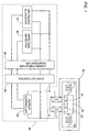
- the liner vibration motor comprises a stator 10 with a single winding 11 and a vibrator 20 embedded with a set of permanent magnets 21 and 22 .
- the stator 10 is mounted to a frame 30 to which the vibrator 20 is coupled by means of springs 31 and 32 .
- the winding 11 is energized by a controller 40 to generate a magnetic field which interacts with the permanent magnets 21 and 22 to develop a driving force of vibrating the vibrator 20 linearly with respect to the stator 10 between the opposite ends of the frame 30 .
- the springs 31 and 32 are cooperative with a magnetic compliance of the motor to give an oscillation system having a natural frequency so that the vibrator 20 vibrates at substantially a fixed frequency.
- the controller 40 includes an output controller 50 which is connected to supply a driving current in the form of a pulse-width-modulated (PWM) signal to the winding 11 for developing the driving force of moving the vibrator 20 . That is, the output controller 50 provides an ON-period of varying width during which the drive current is fed to the winding. A feedback control is made to vary the ON-period in accordance with an ongoing motion detected for the vibrator 20 in order to drive the vibrator 20 at a predetermined amplitude.
- the controller 40 includes an amplitude detector 60 which is connected to the winding 11 to monitor a voltage developed across the winding 11 as a parameter indicating the ongoing motion of the vibrator 20 .
- the monitoring of the voltage is done within an OFF-period of feeding no driving current to the winding 11 . Otherwise, i.e., if the monitoring be done within the ON-period of feeding the driving current, the monitored voltage would involve a component resulting from the driving current and therefore could not be indicative of the ongoing motion of the vibrator 20 .
- Also included in the controller 40 is an OFF-period allocator 70 which issues to the output controller 50 an allocation signal determining the start and end of the OFF-period so that the output controller 50 gives the OFF-period of not feeding the driving current to the winding 11 .
- the allocator 70 determines the start and end of the OFF-period based upon a reference time at which the vibrator 20 sees a maximum displacement or moves to one stroke-end of the vibration. It is known that, when the vibrator 20 sees the maximum displacement during the OFF-period, a voltage across the winding 11 becomes zero. In view of this, the allocator 70 monitors the voltage across the winding 11 to acknowledge the reference time when the voltage becomes zero. Further, the controller 40 includes a start-up controller 80 and a lowered amplitude compensator 90 . The start-up controller 80 defines a start-up sequence of feeding the drive current over several cycles of the vibration without providing the OFF-period for successfully starting the vibration.
- the compensator 90 is provided to deal with an unexpected lowering of the ongoing amplitude and restore the vibration of the intended amplitude quickly by feeding the drive current to a maximum extent without providing the OFF-period over the following several cycles of the vibration after detection of the lowered ongoing amplitude.
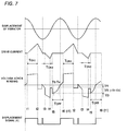
- the ON-period and the OFF-periods are determined in a manner as shown in FIG. 2 which includes a displacement curve D of the vibrator, the drive current Id, the voltage V developed across the winding, a displacement signal X for detection of the maximum displacement, and a speed signal S for detection of the speed of the vibrator 20 .
- the ON-periods T ON1 and T ON2 are set to appear respectively in the adjacent half cycles of the vibration so that the drive current is fed in each half cycle to force the vibrator in each direction.
- the OFF-period T OFF is required, it is set to appear only in one half cycle subsequent to the ON-period T ON2 in such a manner that the vibrator sees the maximum displacement during this OFF period T OFF .
- Operation of the control system is now explained with reference to FIG. 2 and a flow chart of FIG. 3.
- the start-up sequence is made in which the start-up controller 80 operates to determine the maximum width of the ON-period within each half cycle of the vibration as well as to activate a start-up counter so that the start-up sequence continues over initial cycles of the vibration.
- the start-up sequence is judged to continue and a control proceeds to set a start-up mode on, followed by that the output controller 50 determines the start and end timing of the ON-periods and supplies the drive current during the ON-periods for driving the vibrator 20 .
- the OFF-period allocator 70 is rendered inactive so as not to provide the OFF-period.
- the OFF-period allocator 70 is operative to provide the first OFF-period within which the vibrator is expected to see the maximum displacement, as shown in FIG. 2. That is, the allocation signal indicating the start t5 and end t6 of the OFF-period is fed from the allocator 70 to the output controller 50 . At this time, the output controller 50 determines the ON-periods of suitable width and therefore provide the ON-periods for feeding the drive current, and the OFF-period for detection of the ongoing amplitude.
- the output controller 50 determines the ON-periods T ON1 and T ON2 which starts and ends respectively at times t1 and t2, and times t3 and t4. Based upon these settings the output controller 50 feeds the drive current for driving the vibrator while leaving the OFF-period T OFF (t5 to t6), after which the control proceeds to a normal feedback control mode.
- the OFF-period allocator 70 is operative to obtain within the OFF-period the reference time T0 at which the voltage across the winding becomes zero as indicative of that the vibrator 20 reaches the maximum displacement.
- reference time T0 serves as a basis upon which the next ON-periods as well as the next OFF-period are set on a time axis.
- the time difference Ts is indicative of an acceleration of the moving vibrator 20 at the particular time or phase of the vibration, and is processed to obtain the ongoing amplitude expected for the vibrator 20 .
- the ongoing amplitude can be definitely determined from the acceleration due to the fact that the vibrator oscillates at the fixed frequency along a sinusoidal curve.
- the acceleration at the particular time or phase can induce a specific sinusoidal curve with a specific amplitude.
- the voltage indicative of the speed of the vibrator at the particular time can definitely induce the ongoing amplitude. Therefore, the amplitude detector could monitor the voltage at the particular time to obtain the ongoing amplitude.
- the detector 60 comprises an amplifier 61 , a pair of comparators 62 and 63 , and an amplitude calculator 64 .
- the amplifier 61 amplifies the voltage across the winding 11 to provide the resulting amplified voltage to the comparators 62 and 63 .
- the first comparator 62 compares the amplified voltage with a first reference voltage corresponding to Vo to provide the displacement signal X which becomes high when the former voltage proceeds the latter, as shown in FIG. 2.
- the second comparator 63 compares the amplified voltage with a second reference voltage corresponding to V 1 and provides the speed signal S which becomes high when the former voltage exceeds the latter, as shown in FIG.
- the signals X and S are fed to the amplitude calculator 64 where the signals are processed to obtain the time difference Ts and calculate the ongoing amplitude from the time difference as discussed in the above.
- calculated ongoing amplitude is fed back to the output controller 50 which responds to turn on and off transistors 51 to 54 of a driver 55 for feeding the drive current during the variable ON-periods.
- the output controller 50 determines the width of the next ON-period in compensation for the detected ongoing amplitude in order to keep the vibration amplitude constant. Then, the OFF-period allocator 70 sets the start and end timings t5 and t6 of the next OFF-period based on the reference time T 0 . Subsequently, the output controller 50 sets the start and end timings t1 and t2 and t3 and t4 of the next ON-periods in consideration of the determined width of the ON-period and the start and end timing of the next OFF-period.
- the output controller 50 operates to feed the drive current during the ON-periods for driving the vibrator 20 .
- the OFF-period is set in each following cycle of the vibration to determine the reference time T 0 and monitor the ongoing voltage for continued feedback control of the motor based upon the monitored ongoing amplitude unless the ongoing amplitude becomes lower than the minimum reference level.
- the lowered amplitude compensator 90 is provided to monitor the ongoing amplitude and issues a restriction signal when the monitored ongoing amplitude becomes lower than the minimum reference level.
- a restore mode is set on, instructing the output controller 50 to provide no OFF-period and provide the ON-period of maximum width for feeding the drive current sufficiently in order to rapidly restore the vibration of the intended amplitude.
- the output controller 50 determines the start and end of the elongated ON-period and feeds the drive current in the immediately subsequent one cycle of the vibration.
- the restoring routine begins with the determination of the maximum ON-period followed by activating a restore counter. Until the restore counter reaches predetermined counts, the output controller 50 feeds the drive current during the elongated ON-period for driving the vibrator at the maximum force. When the restore counter reaches the predetermined counts, the restore mode is set off so that the output counter 50 provides the ON-period as well as the OFF-period by setting the start and end timings respectively for the ON-period and the OFF-period and feed the drive current. Thereafter, the control sequence goes back to the feedback control mode.
- the two ON-periods are set in each cycle of the vibration in such a manner that the first ON-period T ON1 appearing in one half cycle has a fixed width and the second ON-period T ON2 appearing in the other half cycle has a variable width responsible for the feedback control.
- the PWM control is required only during the half cycle of the vibration, thereby simplifying a structure of controlling the switching transistors of the driver 55 responsible for feeding the drive current to the winding.
- the second ON-period T ON2 has a limited width to afford the OFF-period in the same half cycle in which the drive current as well as a residual current does not flow. Also, the OFF-period is set to terminate shortly after the timing when the vibration reaches the maximum displacement so that the ON-period T ON1 starts just after the timing for increased driving efficiency of the motor.
- the OFF-period is set in the half cycle of the vibration where the vibrator moves in one particular direction
- the OFF-period T OFF may be set to appear alternately in one half cycle and the other half cycle of the vibration, as shown in FIG. 5, so that the ongoing amplitude can be detected while the vibrator moves in one direction at a time and in the opposite direction at the next time.
- the OFF-period T OFF may be set to appear once within several cycles of the vibration. In this condition, the feedback control of varying the ON-periods may be made stepwise within the several cycles of the variation.
- Times T3 and T4 are set to be within the OFF-period and are measured from the reference time T0.
- obtained voltage difference Vs is indicative of the acceleration of the vibrator at the particular time and is processed to give the ongoing amplitude for effecting the feedback control.
Landscapes
- Engineering & Computer Science (AREA)
- Power Engineering (AREA)
- Control Of Linear Motors (AREA)
- Reciprocating, Oscillating Or Vibrating Motors (AREA)
Applications Claiming Priority (2)
| Application Number | Priority Date | Filing Date | Title |
|---|---|---|---|
| JP18091199A JP3931487B2 (ja) | 1999-06-25 | 1999-06-25 | リニア振動モータの駆動制御方法 |
| JP18091199 | 1999-06-25 |
Publications (3)
| Publication Number | Publication Date |
|---|---|
| EP1063760A2 true EP1063760A2 (de) | 2000-12-27 |
| EP1063760A3 EP1063760A3 (de) | 2001-12-05 |
| EP1063760B1 EP1063760B1 (de) | 2013-02-27 |
Family
ID=16091459
Family Applications (1)
| Application Number | Title | Priority Date | Filing Date |
|---|---|---|---|
| EP00112726A Expired - Lifetime EP1063760B1 (de) | 1999-06-25 | 2000-06-15 | Regelung für einen linearen Vibrationsmotor |
Country Status (4)
| Country | Link |
|---|---|
| US (1) | US6351089B1 (de) |
| EP (1) | EP1063760B1 (de) |
| JP (1) | JP3931487B2 (de) |
| CN (1) | CN1216449C (de) |
Cited By (13)
| Publication number | Priority date | Publication date | Assignee | Title |
|---|---|---|---|---|
| WO2004001948A1 (en) | 2002-06-24 | 2003-12-31 | Koninklijke Philips Electronics N.V. | System and method for determining the resonant frequency of an oscillating appliance, in particular a power toothbrush |
| WO2004004112A1 (de) * | 2002-06-29 | 2004-01-08 | Braun Gmbh | Verfahren zum steuern eines oszillierenden elektromotors eines elektrischen kleingeräts |
| EP1450471A1 (de) * | 2003-02-21 | 2004-08-25 | Matsushita Electric Industrial Co., Ltd. | Motorantriebsvorrichtung für einen linear vibrierenden Motor |
| EP1469580A1 (de) * | 2003-04-14 | 2004-10-20 | Matsushita Electric Industrial Co., Ltd. | Motorantriebsvorrichtung für einen linear vibrierenden Motor |
| EP1231706A3 (de) * | 2001-01-26 | 2005-01-05 | Matsushita Electric Works, Ltd. | Regelungsvorrichtung für einen linear schwingenden Motor und Verfahren zu seiner Regelung |
| EP2106019A1 (de) | 2008-03-26 | 2009-09-30 | Panasonic Electric Works Co., Ltd. | Verfahren zur Steuerung des Betriebs eines linearen Vibrations-Motors |
| EP2407298A3 (de) * | 2010-07-14 | 2013-11-27 | Dukane Corporation | Vibrationsschweißsystem mit einem Paar von Elektromagneten |
| US9121753B2 (en) | 2013-02-06 | 2015-09-01 | Analog Devices Global | Control techniques for motor driven systems utilizing back-EMF measurement techniques |
| EP2875918A4 (de) * | 2012-07-18 | 2015-12-09 | Panasonic Ip Man Co Ltd | Epiliervorrichtung sowie verfahren zur ansteuerung einer epiliervorrichtung |
| US9688017B2 (en) | 2013-05-14 | 2017-06-27 | Dukan IAS, LLC | Vibration welders with high frequency vibration, position motion control, and delayed weld motion |
| EP2667504A4 (de) * | 2011-01-21 | 2018-03-07 | Panasonic Corporation | Verfahren zur ansteuerung eines linearaktuators |
| WO2022240523A1 (en) * | 2021-05-13 | 2022-11-17 | Microsoft Technology Licensing, Llc | Active control and calibration of haptic trackpad |
| EP4145697A1 (de) * | 2021-09-01 | 2023-03-08 | Braun GmbH | Motoreinheit und körperpflegevorrichtung mit einer motoreinheit |
Families Citing this family (33)
| Publication number | Priority date | Publication date | Assignee | Title |
|---|---|---|---|---|
| US6883333B2 (en) * | 2002-11-12 | 2005-04-26 | The Penn State Research Foundation | Sensorless control of a harmonically driven electrodynamic machine for a thermoacoustic device or variable load |
| JP4570343B2 (ja) * | 2003-08-01 | 2010-10-27 | シナノケンシ株式会社 | 電磁式ポンプ |
| DE102004010846A1 (de) * | 2004-03-05 | 2005-09-22 | BSH Bosch und Siemens Hausgeräte GmbH | Vorrichtung zur Regelung des Ankerhubs in einem reversierenden Linearantrieb |
| JP4315044B2 (ja) | 2004-04-19 | 2009-08-19 | パナソニック電工株式会社 | リニア振動モータ |
| JP2009240047A (ja) * | 2008-03-26 | 2009-10-15 | Panasonic Electric Works Co Ltd | 電磁アクチュエータの駆動方法 |
| EP2358484A1 (de) | 2008-11-21 | 2011-08-24 | Hadar Magali | Rebound-effektor |
| EP2284987B1 (de) * | 2009-08-12 | 2019-02-06 | Braun GmbH | Verfahren und Vorrichtung zur Einstellung der Frequenz eines Antriebsstroms eines Elektromotors |
| JP5715759B2 (ja) | 2010-01-28 | 2015-05-13 | セミコンダクター・コンポーネンツ・インダストリーズ・リミテッド・ライアビリティ・カンパニー | リニア振動モータの駆動制御回路 |
| JP5603607B2 (ja) * | 2010-01-28 | 2014-10-08 | セミコンダクター・コンポーネンツ・インダストリーズ・リミテッド・ライアビリティ・カンパニー | リニア振動モータの駆動制御回路 |
| JP5601879B2 (ja) | 2010-01-28 | 2014-10-08 | セミコンダクター・コンポーネンツ・インダストリーズ・リミテッド・ライアビリティ・カンパニー | リニア振動モータの駆動制御回路 |
| JP5601845B2 (ja) * | 2010-01-28 | 2014-10-08 | セミコンダクター・コンポーネンツ・インダストリーズ・リミテッド・ライアビリティ・カンパニー | リニア振動モータの駆動制御回路 |
| KR20110117534A (ko) | 2010-04-21 | 2011-10-27 | 삼성전자주식회사 | 진동제어장치 및 방법 |
| JP5705457B2 (ja) | 2010-05-13 | 2015-04-22 | セミコンダクター・コンポーネンツ・インダストリーズ・リミテッド・ライアビリティ・カンパニー | リニア振動モータの駆動制御回路 |
| JP5470154B2 (ja) * | 2010-05-13 | 2014-04-16 | セミコンダクター・コンポーネンツ・インダストリーズ・リミテッド・ライアビリティ・カンパニー | リニア振動モータの駆動制御回路 |
| JP5432057B2 (ja) | 2010-05-13 | 2014-03-05 | セミコンダクター・コンポーネンツ・インダストリーズ・リミテッド・ライアビリティ・カンパニー | リニア振動モータの駆動制御回路 |
| US9427294B2 (en) | 2010-08-19 | 2016-08-30 | Braun Gmbh | Method for operating an electric appliance and electric appliance |
| JP5688559B2 (ja) * | 2011-01-21 | 2015-03-25 | パナソニックIpマネジメント株式会社 | 電気かみそりおよびその制御装置 |
| US20120229264A1 (en) * | 2011-03-09 | 2012-09-13 | Analog Devices, Inc. | Smart linear resonant actuator control |
| WO2012127687A1 (ja) * | 2011-03-24 | 2012-09-27 | 三菱電機株式会社 | リニアモータ駆動装置 |
| KR101190069B1 (ko) * | 2011-05-23 | 2012-10-12 | 엘지전자 주식회사 | 압축기 제어 장치 |
| KR101308317B1 (ko) * | 2013-03-19 | 2013-10-04 | 장석호 | 분할 코일체를 갖는 코일판과 분할 자석을 갖는 왕복 이동형 자석판을 이용한 발전겸용 전동장치 |
| CN103337998B (zh) * | 2013-07-03 | 2015-12-23 | 江苏大学 | 一种磁通反向永磁直线电机的垂向力控制方法 |
| CN104578681B (zh) * | 2015-01-21 | 2017-03-22 | 朱福善 | 一种触发式无刷直流直线电动机的构成及驱动方法 |
| CN106100494B (zh) * | 2016-05-20 | 2019-04-26 | 瑞声科技(新加坡)有限公司 | 线性电机的驱动系统及其驱动方法 |
| CN106230341A (zh) * | 2016-07-20 | 2016-12-14 | 瑞声科技(新加坡)有限公司 | 监控系统及其控制方法 |
| CN106230340A (zh) * | 2016-07-21 | 2016-12-14 | 瑞声科技(新加坡)有限公司 | 线性电机振子振动状态实时监控系统及监控方法 |
| CN106208890A (zh) * | 2016-07-21 | 2016-12-07 | 瑞声科技(新加坡)有限公司 | 线性电机振动一致性的补偿装置及其补偿方法 |
| CN109256928B (zh) * | 2017-07-14 | 2021-02-26 | 讯芯电子科技(中山)有限公司 | 线性振动器 |
| EP3427910B1 (de) * | 2017-07-14 | 2020-08-19 | Braun GmbH | Verfahren zur festlegung des zeitpunktverhaltens eines cyclischen motorverfahrens während der verwendung einer elektrischen haarentfernungsvorrichtung und haarentfernungsvorrichtung |
| JP6704010B2 (ja) * | 2018-04-09 | 2020-06-03 | レノボ・シンガポール・プライベート・リミテッド | 電子機器、及び制御方法 |
| TWI681618B (zh) * | 2018-08-14 | 2020-01-01 | 台睿精工股份有限公司 | 線性振動馬達的控制系統及振動控制方法 |
| CN110994912B (zh) * | 2019-12-09 | 2022-06-03 | Oppo广东移动通信有限公司 | 振动装置及其控制方法、电子设备、存储介质 |
| CN120979279A (zh) * | 2025-05-28 | 2025-11-18 | 深圳术叶创新科技有限公司 | 直线电机的驱动控制方法及相关装置 |
Citations (3)
| Publication number | Priority date | Publication date | Assignee | Title |
|---|---|---|---|---|
| JPS4977116A (de) | 1972-11-29 | 1974-07-25 | ||
| JPS62285655A (ja) | 1986-05-31 | 1987-12-11 | Sharp Corp | 速度帰還方式アクチユエ−タ |
| US5632087A (en) | 1994-03-28 | 1997-05-27 | Matsushita Electric Works, Ltd. | Reciprocatory dry shaver |
Family Cites Families (8)
| Publication number | Priority date | Publication date | Assignee | Title |
|---|---|---|---|---|
| JPS61197776A (ja) * | 1985-02-27 | 1986-09-02 | Sawafuji Electric Co Ltd | 振動型圧縮機 |
| JPS63314191A (ja) * | 1987-06-13 | 1988-12-22 | Ricoh Co Ltd | モ−タの速度制御装置 |
| US5202612A (en) * | 1988-01-29 | 1993-04-13 | Sinano Electric Co., Ltd. | Concrete vibrator |
| US5837885A (en) * | 1994-03-07 | 1998-11-17 | Goodbread; Joseph | Method and device for measuring the characteristics of an oscillating system |
| JP3427555B2 (ja) * | 1994-03-28 | 2003-07-22 | 松下電工株式会社 | 往復式電気かみそり |
| JP3382070B2 (ja) * | 1995-08-28 | 2003-03-04 | 松下電工株式会社 | リニア振動モータの制御装置 |
| US5866998A (en) * | 1997-10-24 | 1999-02-02 | Stmicroelectronics, Inc. | Circuit for improving back emf detection in pulse width modulation mode |
| JP3674364B2 (ja) * | 1999-02-25 | 2005-07-20 | 松下電器産業株式会社 | 振動型電動機及びその駆動制御装置 |
-
1999
- 1999-06-25 JP JP18091199A patent/JP3931487B2/ja not_active Expired - Lifetime
-
2000
- 2000-06-15 EP EP00112726A patent/EP1063760B1/de not_active Expired - Lifetime
- 2000-06-22 US US09/599,450 patent/US6351089B1/en not_active Expired - Lifetime
- 2000-06-23 CN CN001078364A patent/CN1216449C/zh not_active Expired - Lifetime
Patent Citations (3)
| Publication number | Priority date | Publication date | Assignee | Title |
|---|---|---|---|---|
| JPS4977116A (de) | 1972-11-29 | 1974-07-25 | ||
| JPS62285655A (ja) | 1986-05-31 | 1987-12-11 | Sharp Corp | 速度帰還方式アクチユエ−タ |
| US5632087A (en) | 1994-03-28 | 1997-05-27 | Matsushita Electric Works, Ltd. | Reciprocatory dry shaver |
Cited By (24)
| Publication number | Priority date | Publication date | Assignee | Title |
|---|---|---|---|---|
| EP1231706A3 (de) * | 2001-01-26 | 2005-01-05 | Matsushita Electric Works, Ltd. | Regelungsvorrichtung für einen linear schwingenden Motor und Verfahren zu seiner Regelung |
| WO2004001948A1 (en) | 2002-06-24 | 2003-12-31 | Koninklijke Philips Electronics N.V. | System and method for determining the resonant frequency of an oscillating appliance, in particular a power toothbrush |
| EP1518319B1 (de) * | 2002-06-24 | 2017-08-30 | Koninklijke Philips N.V. | Vorrichtung und verfahren zum bestimmen der resonanzfrequenz eines oszillationsgerätes, insbesondere einer motorisch angetriebenen zahnbürste |
| WO2004004112A1 (de) * | 2002-06-29 | 2004-01-08 | Braun Gmbh | Verfahren zum steuern eines oszillierenden elektromotors eines elektrischen kleingeräts |
| DE10229319A1 (de) * | 2002-06-29 | 2004-01-29 | Braun Gmbh | Verfahren zum Steuern eines oszillierenden Elektormotors eines elektrischen Kleingeräts |
| US7180254B2 (en) | 2002-06-29 | 2007-02-20 | Braun Gmbh | Method and apparatus for controlling an oscillating electric motor of a small electric appliance |
| EP1450471A1 (de) * | 2003-02-21 | 2004-08-25 | Matsushita Electric Industrial Co., Ltd. | Motorantriebsvorrichtung für einen linear vibrierenden Motor |
| US7005810B2 (en) | 2003-02-21 | 2006-02-28 | Matsushita Electric Industrial Co., Ltd. | Motor driving apparatus |
| EP1469580A1 (de) * | 2003-04-14 | 2004-10-20 | Matsushita Electric Industrial Co., Ltd. | Motorantriebsvorrichtung für einen linear vibrierenden Motor |
| US7151348B1 (en) | 2003-04-14 | 2006-12-19 | Matsushita Electric Industrila Co., Ltd. | Motor driving apparatus |
| EP2106019A1 (de) | 2008-03-26 | 2009-09-30 | Panasonic Electric Works Co., Ltd. | Verfahren zur Steuerung des Betriebs eines linearen Vibrations-Motors |
| RU2395156C1 (ru) * | 2008-03-26 | 2010-07-20 | Панасоник Электрик Воркс Ко., Лтд. | Способ управления линейным вибрационным двигателем |
| US8721817B2 (en) | 2010-07-14 | 2014-05-13 | Dukane Corporation | Vibration welding system |
| EP2977185A1 (de) * | 2010-07-14 | 2016-01-27 | Dukane Corporation | Vibrationsschweisssystem |
| EP2407298A3 (de) * | 2010-07-14 | 2013-11-27 | Dukane Corporation | Vibrationsschweißsystem mit einem Paar von Elektromagneten |
| EP2667504A4 (de) * | 2011-01-21 | 2018-03-07 | Panasonic Corporation | Verfahren zur ansteuerung eines linearaktuators |
| EP2875918A4 (de) * | 2012-07-18 | 2015-12-09 | Panasonic Ip Man Co Ltd | Epiliervorrichtung sowie verfahren zur ansteuerung einer epiliervorrichtung |
| US9121753B2 (en) | 2013-02-06 | 2015-09-01 | Analog Devices Global | Control techniques for motor driven systems utilizing back-EMF measurement techniques |
| US9688017B2 (en) | 2013-05-14 | 2017-06-27 | Dukan IAS, LLC | Vibration welders with high frequency vibration, position motion control, and delayed weld motion |
| WO2022240523A1 (en) * | 2021-05-13 | 2022-11-17 | Microsoft Technology Licensing, Llc | Active control and calibration of haptic trackpad |
| US11687160B2 (en) | 2021-05-13 | 2023-06-27 | Microsoft Technology Licensing, Llc | Active control and calibration of haptic trackpad |
| EP4145697A1 (de) * | 2021-09-01 | 2023-03-08 | Braun GmbH | Motoreinheit und körperpflegevorrichtung mit einer motoreinheit |
| WO2023031820A1 (en) | 2021-09-01 | 2023-03-09 | Braun Gmbh | Motor unit and personal care device comprising a motor unit |
| US11881799B2 (en) | 2021-09-01 | 2024-01-23 | Braun Gmbh | Motor unit and personal care device comprising a motor unit |
Also Published As
| Publication number | Publication date |
|---|---|
| CN1288285A (zh) | 2001-03-21 |
| CN1216449C (zh) | 2005-08-24 |
| EP1063760A3 (de) | 2001-12-05 |
| JP2001016892A (ja) | 2001-01-19 |
| EP1063760B1 (de) | 2013-02-27 |
| US6351089B1 (en) | 2002-02-26 |
| JP3931487B2 (ja) | 2007-06-13 |
Similar Documents
| Publication | Publication Date | Title |
|---|---|---|
| US6351089B1 (en) | Control system for a linear vibration motor | |
| US6441571B1 (en) | Vibrating linear actuator and method of operating same | |
| EP0860933B1 (de) | Linearer Vibrationsmotor und Verfahren zum Steuern dafür | |
| EP2106019B1 (de) | Verfahren zur Steuerung des Betriebs eines linearen Vibrations-Motors | |
| JP3418507B2 (ja) | 圧電振動制御方法 | |
| JP4315044B2 (ja) | リニア振動モータ | |
| KR100819598B1 (ko) | 압전진동 부품공급기를 제어하는 장치 및 방법 | |
| JP7145985B2 (ja) | アクチュエータ制御装置および方法 | |
| US6181090B1 (en) | Drive control method for linear oscillating motors and a linear oscillating motor | |
| US9537441B2 (en) | Epilator and method for driving epilator | |
| KR100450537B1 (ko) | 부품공급기 및 그 제어방법 | |
| US7154208B2 (en) | Control apparatus for vibration type actuator | |
| JP3875307B2 (ja) | 振動運動を発生する振動溶接装置の操作周波数の調節方法及び装置 | |
| US20050231140A1 (en) | Control apparatus for vibration type actuator | |
| JP2002128261A (ja) | 電磁式パーツフィーダの制御方法と装置 | |
| JP3347470B2 (ja) | 振動型アクチュエーター装置 | |
| KR20170019754A (ko) | 피에조 액추에이터 구동 방법 및 장치 | |
| US5266879A (en) | Stepping motor driving circuit | |
| JP6667684B2 (ja) | 振動発生器の制御方法、モバイル機器、および振動発生器 | |
| HK1136392A (en) | Method for controlling operation of a linear vibration motor | |
| JP2002352947A (ja) | 誘導加熱調理器 | |
| JP2893919B2 (ja) | 振動機の駆動制御装置 | |
| EP1367010A1 (de) | Zuführeinrichtung und Steuerungsverfahren dafür | |
| JP2000324860A5 (de) | ||
| MXPA97002683A (en) | Current shaping in reluctance machines |
Legal Events
| Date | Code | Title | Description |
|---|---|---|---|
| PUAI | Public reference made under article 153(3) epc to a published international application that has entered the european phase |
Free format text: ORIGINAL CODE: 0009012 |
|
| AK | Designated contracting states |
Kind code of ref document: A2 Designated state(s): AT BE CH CY DE DK ES FI FR GB GR IE IT LI LU MC NL PT SE |
|
| AX | Request for extension of the european patent |
Free format text: AL;LT;LV;MK;RO;SI |
|
| PUAL | Search report despatched |
Free format text: ORIGINAL CODE: 0009013 |
|
| AK | Designated contracting states |
Kind code of ref document: A3 Designated state(s): AT BE CH CY DE DK ES FI FR GB GR IE IT LI LU MC NL PT SE |
|
| AX | Request for extension of the european patent |
Free format text: AL;LT;LV;MK;RO;SI |
|
| 17P | Request for examination filed |
Effective date: 20020104 |
|
| AKX | Designation fees paid |
Free format text: AT BE CH CY DE DK ES FI FR GB GR IE IT LI LU MC NL PT SE |
|
| RAP1 | Party data changed (applicant data changed or rights of an application transferred) |
Owner name: PANASONIC ELECTRIC WORKS CO., LTD. |
|
| 17Q | First examination report despatched |
Effective date: 20090507 |
|
| RAP1 | Party data changed (applicant data changed or rights of an application transferred) |
Owner name: PANASONIC CORPORATION |
|
| GRAP | Despatch of communication of intention to grant a patent |
Free format text: ORIGINAL CODE: EPIDOSNIGR1 |
|
| GRAP | Despatch of communication of intention to grant a patent |
Free format text: ORIGINAL CODE: EPIDOSNIGR1 |
|
| GRAS | Grant fee paid |
Free format text: ORIGINAL CODE: EPIDOSNIGR3 |
|
| GRAA | (expected) grant |
Free format text: ORIGINAL CODE: 0009210 |
|
| AK | Designated contracting states |
Kind code of ref document: B1 Designated state(s): AT BE CH CY DE DK ES FI FR GB GR IE IT LI LU MC NL PT SE |
|
| REG | Reference to a national code |
Ref country code: GB Ref legal event code: FG4D |
|
| REG | Reference to a national code |
Ref country code: CH Ref legal event code: EP |
|
| REG | Reference to a national code |
Ref country code: AT Ref legal event code: REF Ref document number: 598939 Country of ref document: AT Kind code of ref document: T Effective date: 20130315 |
|
| REG | Reference to a national code |
Ref country code: IE Ref legal event code: FG4D |
|
| REG | Reference to a national code |
Ref country code: DE Ref legal event code: R096 Ref document number: 60047846 Country of ref document: DE Effective date: 20130425 |
|
| REG | Reference to a national code |
Ref country code: AT Ref legal event code: MK05 Ref document number: 598939 Country of ref document: AT Kind code of ref document: T Effective date: 20130227 |
|
| PG25 | Lapsed in a contracting state [announced via postgrant information from national office to epo] |
Ref country code: AT Free format text: LAPSE BECAUSE OF FAILURE TO SUBMIT A TRANSLATION OF THE DESCRIPTION OR TO PAY THE FEE WITHIN THE PRESCRIBED TIME-LIMIT Effective date: 20130227 Ref country code: ES Free format text: LAPSE BECAUSE OF FAILURE TO SUBMIT A TRANSLATION OF THE DESCRIPTION OR TO PAY THE FEE WITHIN THE PRESCRIBED TIME-LIMIT Effective date: 20130607 Ref country code: SE Free format text: LAPSE BECAUSE OF FAILURE TO SUBMIT A TRANSLATION OF THE DESCRIPTION OR TO PAY THE FEE WITHIN THE PRESCRIBED TIME-LIMIT Effective date: 20130227 |
|
| REG | Reference to a national code |
Ref country code: NL Ref legal event code: VDEP Effective date: 20130227 |
|
| PG25 | Lapsed in a contracting state [announced via postgrant information from national office to epo] |
Ref country code: BE Free format text: LAPSE BECAUSE OF FAILURE TO SUBMIT A TRANSLATION OF THE DESCRIPTION OR TO PAY THE FEE WITHIN THE PRESCRIBED TIME-LIMIT Effective date: 20130227 Ref country code: PT Free format text: LAPSE BECAUSE OF FAILURE TO SUBMIT A TRANSLATION OF THE DESCRIPTION OR TO PAY THE FEE WITHIN THE PRESCRIBED TIME-LIMIT Effective date: 20130627 Ref country code: GR Free format text: LAPSE BECAUSE OF FAILURE TO SUBMIT A TRANSLATION OF THE DESCRIPTION OR TO PAY THE FEE WITHIN THE PRESCRIBED TIME-LIMIT Effective date: 20130528 Ref country code: FI Free format text: LAPSE BECAUSE OF FAILURE TO SUBMIT A TRANSLATION OF THE DESCRIPTION OR TO PAY THE FEE WITHIN THE PRESCRIBED TIME-LIMIT Effective date: 20130227 |
|
| PG25 | Lapsed in a contracting state [announced via postgrant information from national office to epo] |
Ref country code: NL Free format text: LAPSE BECAUSE OF FAILURE TO SUBMIT A TRANSLATION OF THE DESCRIPTION OR TO PAY THE FEE WITHIN THE PRESCRIBED TIME-LIMIT Effective date: 20130227 Ref country code: DK Free format text: LAPSE BECAUSE OF FAILURE TO SUBMIT A TRANSLATION OF THE DESCRIPTION OR TO PAY THE FEE WITHIN THE PRESCRIBED TIME-LIMIT Effective date: 20130227 |
|
| PG25 | Lapsed in a contracting state [announced via postgrant information from national office to epo] |
Ref country code: CY Free format text: LAPSE BECAUSE OF FAILURE TO SUBMIT A TRANSLATION OF THE DESCRIPTION OR TO PAY THE FEE WITHIN THE PRESCRIBED TIME-LIMIT Effective date: 20130227 |
|
| PG25 | Lapsed in a contracting state [announced via postgrant information from national office to epo] |
Ref country code: IT Free format text: LAPSE BECAUSE OF FAILURE TO SUBMIT A TRANSLATION OF THE DESCRIPTION OR TO PAY THE FEE WITHIN THE PRESCRIBED TIME-LIMIT Effective date: 20130227 |
|
| PLBE | No opposition filed within time limit |
Free format text: ORIGINAL CODE: 0009261 |
|
| STAA | Information on the status of an ep patent application or granted ep patent |
Free format text: STATUS: NO OPPOSITION FILED WITHIN TIME LIMIT |
|
| PG25 | Lapsed in a contracting state [announced via postgrant information from national office to epo] |
Ref country code: MC Free format text: LAPSE BECAUSE OF FAILURE TO SUBMIT A TRANSLATION OF THE DESCRIPTION OR TO PAY THE FEE WITHIN THE PRESCRIBED TIME-LIMIT Effective date: 20130227 |
|
| REG | Reference to a national code |
Ref country code: CH Ref legal event code: PL |
|
| 26N | No opposition filed |
Effective date: 20131128 |
|
| GBPC | Gb: european patent ceased through non-payment of renewal fee |
Effective date: 20130615 |
|
| REG | Reference to a national code |
Ref country code: DE Ref legal event code: R097 Ref document number: 60047846 Country of ref document: DE Effective date: 20131128 |
|
| REG | Reference to a national code |
Ref country code: IE Ref legal event code: MM4A |
|
| REG | Reference to a national code |
Ref country code: FR Ref legal event code: ST Effective date: 20140228 |
|
| PG25 | Lapsed in a contracting state [announced via postgrant information from national office to epo] |
Ref country code: LI Free format text: LAPSE BECAUSE OF NON-PAYMENT OF DUE FEES Effective date: 20130630 Ref country code: GB Free format text: LAPSE BECAUSE OF NON-PAYMENT OF DUE FEES Effective date: 20130615 Ref country code: CH Free format text: LAPSE BECAUSE OF NON-PAYMENT OF DUE FEES Effective date: 20130630 Ref country code: IE Free format text: LAPSE BECAUSE OF NON-PAYMENT OF DUE FEES Effective date: 20130615 |
|
| PG25 | Lapsed in a contracting state [announced via postgrant information from national office to epo] |
Ref country code: FR Free format text: LAPSE BECAUSE OF NON-PAYMENT OF DUE FEES Effective date: 20130701 |
|
| PG25 | Lapsed in a contracting state [announced via postgrant information from national office to epo] |
Ref country code: LU Free format text: LAPSE BECAUSE OF NON-PAYMENT OF DUE FEES Effective date: 20130615 |
|
| PGFP | Annual fee paid to national office [announced via postgrant information from national office to epo] |
Ref country code: DE Payment date: 20190619 Year of fee payment: 20 |
|
| REG | Reference to a national code |
Ref country code: DE Ref legal event code: R071 Ref document number: 60047846 Country of ref document: DE |