EP1064080B1 - Reduction de NOx dans des gaz d' échappement - Google Patents
Reduction de NOx dans des gaz d' échappement Download PDFInfo
- Publication number
- EP1064080B1 EP1064080B1 EP99912194A EP99912194A EP1064080B1 EP 1064080 B1 EP1064080 B1 EP 1064080B1 EP 99912194 A EP99912194 A EP 99912194A EP 99912194 A EP99912194 A EP 99912194A EP 1064080 B1 EP1064080 B1 EP 1064080B1
- Authority
- EP
- European Patent Office
- Prior art keywords
- equipment
- heat exchanging
- matrix
- gas
- hot part
- Prior art date
- Legal status (The legal status is an assumption and is not a legal conclusion. Google has not performed a legal analysis and makes no representation as to the accuracy of the status listed.)
- Expired - Lifetime
Links
Images
Classifications
-
- F—MECHANICAL ENGINEERING; LIGHTING; HEATING; WEAPONS; BLASTING
- F23—COMBUSTION APPARATUS; COMBUSTION PROCESSES
- F23G—CREMATION FURNACES; CONSUMING WASTE PRODUCTS BY COMBUSTION
- F23G7/00—Incinerators or other apparatus for consuming industrial waste, e.g. chemicals
- F23G7/06—Incinerators or other apparatus for consuming industrial waste, e.g. chemicals of waste gases or noxious gases, e.g. exhaust gases
- F23G7/07—Incinerators or other apparatus for consuming industrial waste, e.g. chemicals of waste gases or noxious gases, e.g. exhaust gases in which combustion takes place in the presence of catalytic material
-
- B—PERFORMING OPERATIONS; TRANSPORTING
- B01—PHYSICAL OR CHEMICAL PROCESSES OR APPARATUS IN GENERAL
- B01D—SEPARATION
- B01D53/00—Separation of gases or vapours; Recovering vapours of volatile solvents from gases; Chemical or biological purification of waste gases, e.g. engine exhaust gases, smoke, fumes, flue gases, aerosols
- B01D53/34—Chemical or biological purification of waste gases
- B01D53/46—Removing components of defined structure
- B01D53/54—Nitrogen compounds
- B01D53/56—Nitrogen oxides
-
- B—PERFORMING OPERATIONS; TRANSPORTING
- B01—PHYSICAL OR CHEMICAL PROCESSES OR APPARATUS IN GENERAL
- B01D—SEPARATION
- B01D53/00—Separation of gases or vapours; Recovering vapours of volatile solvents from gases; Chemical or biological purification of waste gases, e.g. engine exhaust gases, smoke, fumes, flue gases, aerosols
- B01D53/34—Chemical or biological purification of waste gases
- B01D53/74—General processes for purification of waste gases; Apparatus or devices specially adapted therefor
- B01D53/86—Catalytic processes
- B01D53/8621—Removing nitrogen compounds
- B01D53/8625—Nitrogen oxides
- B01D53/8631—Processes characterised by a specific device
-
- B—PERFORMING OPERATIONS; TRANSPORTING
- B01—PHYSICAL OR CHEMICAL PROCESSES OR APPARATUS IN GENERAL
- B01D—SEPARATION
- B01D53/00—Separation of gases or vapours; Recovering vapours of volatile solvents from gases; Chemical or biological purification of waste gases, e.g. engine exhaust gases, smoke, fumes, flue gases, aerosols
- B01D53/34—Chemical or biological purification of waste gases
- B01D53/74—General processes for purification of waste gases; Apparatus or devices specially adapted therefor
- B01D53/86—Catalytic processes
- B01D53/869—Multiple step processes
-
- B—PERFORMING OPERATIONS; TRANSPORTING
- B01—PHYSICAL OR CHEMICAL PROCESSES OR APPARATUS IN GENERAL
- B01D—SEPARATION
- B01D53/00—Separation of gases or vapours; Recovering vapours of volatile solvents from gases; Chemical or biological purification of waste gases, e.g. engine exhaust gases, smoke, fumes, flue gases, aerosols
- B01D53/34—Chemical or biological purification of waste gases
- B01D53/92—Chemical or biological purification of waste gases of engine exhaust gases
- B01D53/94—Chemical or biological purification of waste gases of engine exhaust gases by catalytic processes
- B01D53/9404—Removing only nitrogen compounds
- B01D53/9409—Nitrogen oxides
- B01D53/9431—Processes characterised by a specific device
-
- F—MECHANICAL ENGINEERING; LIGHTING; HEATING; WEAPONS; BLASTING
- F01—MACHINES OR ENGINES IN GENERAL; ENGINE PLANTS IN GENERAL; STEAM ENGINES
- F01N—GAS-FLOW SILENCERS OR EXHAUST APPARATUS FOR MACHINES OR ENGINES IN GENERAL; GAS-FLOW SILENCERS OR EXHAUST APPARATUS FOR INTERNAL-COMBUSTION ENGINES
- F01N3/00—Exhaust or silencing apparatus having means for purifying, rendering innocuous, or otherwise treating exhaust
- F01N3/08—Exhaust or silencing apparatus having means for purifying, rendering innocuous, or otherwise treating exhaust for rendering innocuous
- F01N3/10—Exhaust or silencing apparatus having means for purifying, rendering innocuous, or otherwise treating exhaust for rendering innocuous by thermal or catalytic conversion of noxious components of exhaust
- F01N3/18—Exhaust or silencing apparatus having means for purifying, rendering innocuous, or otherwise treating exhaust for rendering innocuous by thermal or catalytic conversion of noxious components of exhaust characterised by methods of operation; Control
- F01N3/20—Exhaust or silencing apparatus having means for purifying, rendering innocuous, or otherwise treating exhaust for rendering innocuous by thermal or catalytic conversion of noxious components of exhaust characterised by methods of operation; Control specially adapted for catalytic conversion
- F01N3/2006—Periodically heating or cooling catalytic reactors, e.g. at cold starting or overheating
- F01N3/2013—Periodically heating or cooling catalytic reactors, e.g. at cold starting or overheating using electric or magnetic heating means
-
- F—MECHANICAL ENGINEERING; LIGHTING; HEATING; WEAPONS; BLASTING
- F01—MACHINES OR ENGINES IN GENERAL; ENGINE PLANTS IN GENERAL; STEAM ENGINES
- F01N—GAS-FLOW SILENCERS OR EXHAUST APPARATUS FOR MACHINES OR ENGINES IN GENERAL; GAS-FLOW SILENCERS OR EXHAUST APPARATUS FOR INTERNAL-COMBUSTION ENGINES
- F01N3/00—Exhaust or silencing apparatus having means for purifying, rendering innocuous, or otherwise treating exhaust
- F01N3/08—Exhaust or silencing apparatus having means for purifying, rendering innocuous, or otherwise treating exhaust for rendering innocuous
- F01N3/10—Exhaust or silencing apparatus having means for purifying, rendering innocuous, or otherwise treating exhaust for rendering innocuous by thermal or catalytic conversion of noxious components of exhaust
- F01N3/18—Exhaust or silencing apparatus having means for purifying, rendering innocuous, or otherwise treating exhaust for rendering innocuous by thermal or catalytic conversion of noxious components of exhaust characterised by methods of operation; Control
- F01N3/20—Exhaust or silencing apparatus having means for purifying, rendering innocuous, or otherwise treating exhaust for rendering innocuous by thermal or catalytic conversion of noxious components of exhaust characterised by methods of operation; Control specially adapted for catalytic conversion
- F01N3/2006—Periodically heating or cooling catalytic reactors, e.g. at cold starting or overheating
- F01N3/2033—Periodically heating or cooling catalytic reactors, e.g. at cold starting or overheating using a fuel burner or introducing fuel into exhaust duct
-
- F—MECHANICAL ENGINEERING; LIGHTING; HEATING; WEAPONS; BLASTING
- F01—MACHINES OR ENGINES IN GENERAL; ENGINE PLANTS IN GENERAL; STEAM ENGINES
- F01N—GAS-FLOW SILENCERS OR EXHAUST APPARATUS FOR MACHINES OR ENGINES IN GENERAL; GAS-FLOW SILENCERS OR EXHAUST APPARATUS FOR INTERNAL-COMBUSTION ENGINES
- F01N3/00—Exhaust or silencing apparatus having means for purifying, rendering innocuous, or otherwise treating exhaust
- F01N3/08—Exhaust or silencing apparatus having means for purifying, rendering innocuous, or otherwise treating exhaust for rendering innocuous
- F01N3/10—Exhaust or silencing apparatus having means for purifying, rendering innocuous, or otherwise treating exhaust for rendering innocuous by thermal or catalytic conversion of noxious components of exhaust
- F01N3/18—Exhaust or silencing apparatus having means for purifying, rendering innocuous, or otherwise treating exhaust for rendering innocuous by thermal or catalytic conversion of noxious components of exhaust characterised by methods of operation; Control
- F01N3/20—Exhaust or silencing apparatus having means for purifying, rendering innocuous, or otherwise treating exhaust for rendering innocuous by thermal or catalytic conversion of noxious components of exhaust characterised by methods of operation; Control specially adapted for catalytic conversion
- F01N3/206—Adding periodically or continuously substances to exhaust gases for promoting purification, e.g. catalytic material in liquid form, NOx reducing agents
- F01N3/2066—Selective catalytic reduction [SCR]
-
- F—MECHANICAL ENGINEERING; LIGHTING; HEATING; WEAPONS; BLASTING
- F01—MACHINES OR ENGINES IN GENERAL; ENGINE PLANTS IN GENERAL; STEAM ENGINES
- F01N—GAS-FLOW SILENCERS OR EXHAUST APPARATUS FOR MACHINES OR ENGINES IN GENERAL; GAS-FLOW SILENCERS OR EXHAUST APPARATUS FOR INTERNAL-COMBUSTION ENGINES
- F01N3/00—Exhaust or silencing apparatus having means for purifying, rendering innocuous, or otherwise treating exhaust
- F01N3/08—Exhaust or silencing apparatus having means for purifying, rendering innocuous, or otherwise treating exhaust for rendering innocuous
- F01N3/10—Exhaust or silencing apparatus having means for purifying, rendering innocuous, or otherwise treating exhaust for rendering innocuous by thermal or catalytic conversion of noxious components of exhaust
- F01N3/24—Exhaust or silencing apparatus having means for purifying, rendering innocuous, or otherwise treating exhaust for rendering innocuous by thermal or catalytic conversion of noxious components of exhaust characterised by constructional aspects of converting apparatus
- F01N3/28—Construction of catalytic reactors
- F01N3/2882—Catalytic reactors combined or associated with other devices, e.g. exhaust silencers or other exhaust purification devices
-
- F—MECHANICAL ENGINEERING; LIGHTING; HEATING; WEAPONS; BLASTING
- F23—COMBUSTION APPARATUS; COMBUSTION PROCESSES
- F23G—CREMATION FURNACES; CONSUMING WASTE PRODUCTS BY COMBUSTION
- F23G7/00—Incinerators or other apparatus for consuming industrial waste, e.g. chemicals
- F23G7/06—Incinerators or other apparatus for consuming industrial waste, e.g. chemicals of waste gases or noxious gases, e.g. exhaust gases
- F23G7/061—Incinerators or other apparatus for consuming industrial waste, e.g. chemicals of waste gases or noxious gases, e.g. exhaust gases with supplementary heating
- F23G7/065—Incinerators or other apparatus for consuming industrial waste, e.g. chemicals of waste gases or noxious gases, e.g. exhaust gases with supplementary heating using gaseous or liquid fuel
- F23G7/066—Incinerators or other apparatus for consuming industrial waste, e.g. chemicals of waste gases or noxious gases, e.g. exhaust gases with supplementary heating using gaseous or liquid fuel preheating the waste gas by the heat of the combustion, e.g. recuperation type incinerator
- F23G7/068—Incinerators or other apparatus for consuming industrial waste, e.g. chemicals of waste gases or noxious gases, e.g. exhaust gases with supplementary heating using gaseous or liquid fuel preheating the waste gas by the heat of the combustion, e.g. recuperation type incinerator using regenerative heat recovery means
-
- F—MECHANICAL ENGINEERING; LIGHTING; HEATING; WEAPONS; BLASTING
- F01—MACHINES OR ENGINES IN GENERAL; ENGINE PLANTS IN GENERAL; STEAM ENGINES
- F01N—GAS-FLOW SILENCERS OR EXHAUST APPARATUS FOR MACHINES OR ENGINES IN GENERAL; GAS-FLOW SILENCERS OR EXHAUST APPARATUS FOR INTERNAL-COMBUSTION ENGINES
- F01N2240/00—Combination or association of two or more different exhaust treating devices, or of at least one such device with an auxiliary device, not covered by indexing codes F01N2230/00 or F01N2250/00, one of the devices being
- F01N2240/02—Combination or association of two or more different exhaust treating devices, or of at least one such device with an auxiliary device, not covered by indexing codes F01N2230/00 or F01N2250/00, one of the devices being a heat exchanger
-
- F—MECHANICAL ENGINEERING; LIGHTING; HEATING; WEAPONS; BLASTING
- F01—MACHINES OR ENGINES IN GENERAL; ENGINE PLANTS IN GENERAL; STEAM ENGINES
- F01N—GAS-FLOW SILENCERS OR EXHAUST APPARATUS FOR MACHINES OR ENGINES IN GENERAL; GAS-FLOW SILENCERS OR EXHAUST APPARATUS FOR INTERNAL-COMBUSTION ENGINES
- F01N2570/00—Exhaust treating apparatus eliminating, absorbing or adsorbing specific elements or compounds
- F01N2570/14—Nitrogen oxides
-
- F—MECHANICAL ENGINEERING; LIGHTING; HEATING; WEAPONS; BLASTING
- F01—MACHINES OR ENGINES IN GENERAL; ENGINE PLANTS IN GENERAL; STEAM ENGINES
- F01N—GAS-FLOW SILENCERS OR EXHAUST APPARATUS FOR MACHINES OR ENGINES IN GENERAL; GAS-FLOW SILENCERS OR EXHAUST APPARATUS FOR INTERNAL-COMBUSTION ENGINES
- F01N2610/00—Adding substances to exhaust gases
- F01N2610/02—Adding substances to exhaust gases the substance being ammonia or urea
-
- Y—GENERAL TAGGING OF NEW TECHNOLOGICAL DEVELOPMENTS; GENERAL TAGGING OF CROSS-SECTIONAL TECHNOLOGIES SPANNING OVER SEVERAL SECTIONS OF THE IPC; TECHNICAL SUBJECTS COVERED BY FORMER USPC CROSS-REFERENCE ART COLLECTIONS [XRACs] AND DIGESTS
- Y02—TECHNOLOGIES OR APPLICATIONS FOR MITIGATION OR ADAPTATION AGAINST CLIMATE CHANGE
- Y02A—TECHNOLOGIES FOR ADAPTATION TO CLIMATE CHANGE
- Y02A50/00—TECHNOLOGIES FOR ADAPTATION TO CLIMATE CHANGE in human health protection, e.g. against extreme weather
- Y02A50/20—Air quality improvement or preservation, e.g. vehicle emission control or emission reduction by using catalytic converters
-
- Y—GENERAL TAGGING OF NEW TECHNOLOGICAL DEVELOPMENTS; GENERAL TAGGING OF CROSS-SECTIONAL TECHNOLOGIES SPANNING OVER SEVERAL SECTIONS OF THE IPC; TECHNICAL SUBJECTS COVERED BY FORMER USPC CROSS-REFERENCE ART COLLECTIONS [XRACs] AND DIGESTS
- Y02—TECHNOLOGIES OR APPLICATIONS FOR MITIGATION OR ADAPTATION AGAINST CLIMATE CHANGE
- Y02T—CLIMATE CHANGE MITIGATION TECHNOLOGIES RELATED TO TRANSPORTATION
- Y02T10/00—Road transport of goods or passengers
- Y02T10/10—Internal combustion engine [ICE] based vehicles
- Y02T10/12—Improving ICE efficiencies
Definitions
- Polluted air and other gases can be purified by heat treatment to such temperatures that the pollutants are oxidised or decomposed.
- US patent 4 267 152 and US patent 4 741 690 describes such processes where the polluted gases are fed through regenerative devices where the heating of a gas is immediately followed by cooling and recovery of the heat content of the gas. In this way heat treatment of the gas to a high temperature can be made in an economical way without a high expenditure of energy.
- the incoming raw gas is in these processes successively heated to the high temperature by means of contact with a matrix of solid material capable of heat transfer to the gas.
- a matrix of solid material capable of heat transfer to the gas.
- the solid matrix there is a temperature gradient so that the gas is first successively heated to a maximum temperature. After attaining its maximum temperature the gas is then cooled in an analogous manner by means of contact with a solid matrix of successively lower temperature.
- the heating and the cooling matrices are separated from each other but used alternatively for heating and cooling purposes according to an alternating direction of gas flow through the matrices.
- the different matrices are alternatively used for heating and cooling of the gas.
- US patent 4 741 690 there is only one continuous matrix through which the gas flow is being fed. The temperature profile in this matrix is such however that when the gas passes through it is first successively heated to a maximum temperature and then successively cooled.
- the operation is regenerative and the gas is fed in alternating directions through the equipment and is successively first heated to a maximum temperature and then cooled.
- the maximum temperature employed is such that it is at or above the temperature that is necessary for the intended oxidation or decomposition reaction to take place.
- Processes and equipment like these are extensively used for the purification of ventilation air from painting and printing processes. It can also be used for the purification of exhaust gases from internal combustion engines. In this and other cases nitrogen oxides are a part of the pollution problem.
- the concentration of nitrogen oxides in the exhaust can reach several thousands of ppm. Good reduction of these nitrogen oxides can be accomplished if the exhaust is first mixed with a corresponding amount of ammonia, urea or other amine compound before it is heat treated in the above described manner. During the heating the mixture will pass through the relevant temperature window for a selective non catalytic reduction (SNCR) reaction where the nitrogen oxides and the amines are transformed to elemental and harmless nitrogen.
- SNCR selective non catalytic reduction
- Diesel engine exhaust for example can thus be purified in the above described process first during the heating phase when nitrogen oxides are removed and then at the high temperature when soot, aldehydes and other organic matter is oxidised. This way of operation of the equipment is described in European patent number EP 609 288 .
- DE4432316 relates to waste gas denitrification and removal of halogenated dibenzodioxin wherein the device has an active DeNOx catalyst arranged on the outlet side for denitrification.
- the present invention according to claim 1 constitutes a way of improving this situation so that the concentration of nitrogen oxides in the outgoing treated gas can be brought down significantly below 50 ppm.
- the improvement is accomplished by the incorporation of catalytically active zones into the heat transfer matrices of earlier designs.
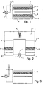
- FIG. 1 An embodiment of the invention is described in figure 1 and another embodiment of the invention is described in figure 2 .
- both figures 1 is a valve mechanism for the direction of air (gas) in alternating directions through the equipment.2 and 3 are connecting ducts for incoming raw and outgoing cleaned gas respectively. 4 and 5 are wind boxes for distribution and collection of air (gas) that goes through the heat transfer matrix 6.
- this matrix is divided into two parts 6 and 6' surrounding a combustion chamber 7 which is absent in the design shown in figure 1 where the heat exchanging matrix stretches all the way between the two wind boxes 4 and 5.
- Both designs comprises means for heating: in figure 1 in the form of electric heaters 8 and in figure 2 in the form of a burner 9.
- both designs also incorporate catalytically active zones 10 and 11 within the heat exchanging matrices.
- the temperature is high in the centre of the heat exchanging matrix 6 and gradually decreases towards top and bottom.
- the temperature is high in the combustion chamber 7 and the upper parts of the heat exchanging matrices 6 and 6' and the temperature gradually decreases towards the bottom of the heat exchanging matrices.
- raw polluted gas is first mixed with ammonia, urea, or other compound able to act as a selective nitrogen oxides reducing agent.
- the mixture is then introduced into a cold end of a heat exchanger matrix and by passing through it is successively heated to oxidation or decomposition temperature which is attained in the inner part of the equipment i.e. the hot centre of the matrix in fig 1 or the uppermost parts of the matrices 6 and 6' and the combustion chamber 7 in fig 2 .
- the mixture is passed through the catalytically active zone of the heat exchanger matrix 6 or 6'.
- nitrogen oxides react with the mixed in reducing agent and are thus removed.
- the catalytic zone is placed in the heat exchanging matrix in such a way that the temperature conditions there are favourable for this reduction and a selective catalytic reaction (SCR) takes place.
- SCR selective catalytic reaction
- the reaction takes place at a substantially lower temperature than an SNCR reaction and this together with the use of catalyst makes a more thorough reduction possible as compared with an operation according to European patent EP 609 288 and lower levels of concentration of nitrogen oxides are obtainable. When the inlet concentration of nitrogen oxides is low the difference becomes significant.
- An important aspect of the invention is that catalyst can be applied in such a way that the reducing activity of the catalyst is retained for a considerable time after the supply of reducing agent has been interrupted.
- the overall reduction efficiency of the equipment thus is not disadvantageously affected by such interruptions in the supply of reducing agent.
- This effect can be so pronounced that the equipment can be modified to comprise only one zone of catalytically active material. This zone is then activated by the supply of reducing agent when this part of the equipment is used as inlet end for the gas stream.
- the active zone is at the outlet end of the equipment the supply of reducing agent is cut off and the reduction of nitrogen oxides takes place in this zone after the high temperature treatment.
- Figure 3 shows such a design with only one catalytically active zone 10.
- the invention has been described above in the conjunction with regenerative equipment using either one heat exchanging matrix or two different matrices surrounding a combustion chamber.
- the direction of flow through the heat exchanging matrix is changed only gradually in the heat exchanging matrix so that different parts of the same matrix have flow in different directions. This is obtained for instance by rotation of a matrix versus fixed inlet and outlet ports or by the use of a rotating valve system working together with a fixed matrix.
- RTOs regenerative thermal oxidisers
- the heat exchanging matrix material is subject to a gas flow that is reversed at regular intervals and the incoming gas is successively heated to a high temperature where oxidation and decomposition takes place.
- the invention is applicable in all these cases.
- the design shown in figures 1 and 3 have the advantage that the equipment is compact and can be made comparatively small which very often is an important aspect when used in various conjunctions together with internal combustion engines.
Landscapes
- Engineering & Computer Science (AREA)
- Chemical & Material Sciences (AREA)
- Chemical Kinetics & Catalysis (AREA)
- Environmental & Geological Engineering (AREA)
- Health & Medical Sciences (AREA)
- Mechanical Engineering (AREA)
- General Engineering & Computer Science (AREA)
- Combustion & Propulsion (AREA)
- Biomedical Technology (AREA)
- Analytical Chemistry (AREA)
- General Chemical & Material Sciences (AREA)
- Oil, Petroleum & Natural Gas (AREA)
- Toxicology (AREA)
- Exhaust Gas Treatment By Means Of Catalyst (AREA)
- Exhaust Gas After Treatment (AREA)
- Incineration Of Waste (AREA)
Claims (5)
- Équipement de purification des gaz utilisant au moins une matrice de transfert de chaleur (6, 6') où le gaz, au cours d'un procédé régénératif, est chauffé jusqu'à la température d'oxydation ou de décomposition, lequel équipement comprend un moyen d'alimentation permettant d'alimenter en agents les gaz qui réduisent les oxydes d'azote pour former un mélange avant d'y introduire au moins une matrice de transfert de chaleur (6, 6'), ladite matrice comprenant :- une zone catalytique (10, 11) qui est active d'un point de vue catalytique pour favoriser la réduction des oxydes d'azote dudit mélange,- une partie chaude équipée de moyens de chauffage (8, 9) pour chauffer ledit mélange à une température permettant une oxydation et une décomposition, et- une partie de transfert de chaleur séparant la zone catalytique de la partie chaude de sorte qu'une température suffisamment basse est maintenue dans la zone catalytique pour que la réaction catalytique ait lieu avant l'oxydation et la décomposition dans la partie chaude.
- Équipement selon la revendication 1, dans lequel au moins une des matrices de transfert de chaleur (6, 6') comprend deux groupes constitués d'une zone catalytique (10, 11) et d'une partie de transfert de chaleur, les deux groupes étant situés de part et d'autre de la partie chaude.
- Équipement selon l'une quelconque des revendications 1 ou 2, dans lequel lesdits moyens de chauffage comprennent une chambre de combustion (7) équipée d'un brûleur (9) située dans la partie chaude.
- Équipement selon l'une quelconque des revendications 1 à 3, lequel équipement est adapté pour interrompre l'alimentation en agent réducteur pendant une courte période de temps tout en modifiant le sens d'écoulement du débit dans l'équipement.
- Équipement selon l'une quelconque des revendications 1 à 4, lequel équipement est adapté pour maintenir l'alimentation en agent réducteur uniquement lorsque le gaz à traiter traverse l'équipement de telle sorte qu'il passe dans ladite zone catalytique avant d'atteindre ladite partie chaude équipée desdits moyens de chauffage.
Applications Claiming Priority (3)
| Application Number | Priority Date | Filing Date | Title |
|---|---|---|---|
| SE9800866 | 1998-03-17 | ||
| SE9800866A SE518812C2 (sv) | 1998-03-17 | 1998-03-17 | Katalytisk regenerativ anordning för rening av gaser |
| PCT/SE1999/000343 WO1999047245A1 (fr) | 1998-03-17 | 1999-03-08 | Commande de pollution |
Publications (2)
| Publication Number | Publication Date |
|---|---|
| EP1064080A1 EP1064080A1 (fr) | 2001-01-03 |
| EP1064080B1 true EP1064080B1 (fr) | 2009-09-16 |
Family
ID=20410567
Family Applications (1)
| Application Number | Title | Priority Date | Filing Date |
|---|---|---|---|
| EP99912194A Expired - Lifetime EP1064080B1 (fr) | 1998-03-17 | 1999-03-08 | Reduction de NOx dans des gaz d' échappement |
Country Status (7)
| Country | Link |
|---|---|
| US (1) | US7399451B1 (fr) |
| EP (1) | EP1064080B1 (fr) |
| JP (1) | JP4435417B2 (fr) |
| AU (1) | AU3061899A (fr) |
| DE (1) | DE69941426D1 (fr) |
| SE (1) | SE518812C2 (fr) |
| WO (1) | WO1999047245A1 (fr) |
Families Citing this family (14)
| Publication number | Priority date | Publication date | Assignee | Title |
|---|---|---|---|---|
| SE0101716D0 (sv) * | 2001-05-16 | 2001-05-16 | Catator Ab | Method and device for processing nitrogen-based gases |
| US8124017B2 (en) | 2004-09-30 | 2012-02-28 | Babcock Power Environmental Inc. | Systems and methods for high efficiency regenerative selective catalytic reduction |
| US7758831B2 (en) * | 2004-09-30 | 2010-07-20 | Babcock Power Environmental Inc. | Systems and methods for removing materials from flue gas via regenerative selective catalytic reduction |
| DE102007056165A1 (de) * | 2007-11-21 | 2009-05-28 | Epcos Ag | Überspannungsableiter mit thermischem Überlastschutz |
| US8038957B1 (en) | 2009-06-25 | 2011-10-18 | Cleary James M | Electric catalytic oxidizer |
| AT507773B1 (de) * | 2009-07-15 | 2010-08-15 | Scheuch Gmbh | Verfahren und vorrichtung zur entstickung von rauchgasen |
| CN102626590B (zh) * | 2011-07-18 | 2013-12-04 | 西南化工研究设计院 | 一种低浓度有机可燃气体催化氧化装置及热量利用系统 |
| DE102013100856A1 (de) * | 2013-01-29 | 2014-07-31 | Chemisch Thermische Prozesstechnik Gmbh | Verfahren und Vorrichtung zur Reinigung von Abgasen |
| AT515887A1 (de) | 2014-05-20 | 2015-12-15 | Ge Jenbacher Gmbh & Co Og | Verfahren zum Anfahren eines Thermoreaktors |
| AT517670B1 (de) * | 2015-09-04 | 2023-03-15 | Innio Jenbacher Gmbh & Co Og | Abgasnachbehandlungsvorrichtung |
| DE102017101507B4 (de) * | 2017-01-26 | 2022-10-13 | Chemisch Thermische Prozesstechnik Gmbh | Verfahren und Vorrichtung zur Abgasreinigung |
| CN108980867A (zh) * | 2018-10-15 | 2018-12-11 | 上海环境工程设计研究院有限公司 | 立式rto焚烧系统 |
| CN111780096B (zh) * | 2020-07-21 | 2023-04-04 | 湖北鼎博丰新能源发展有限公司 | 一种天然气锅炉低氮燃烧系统 |
| KR102526115B1 (ko) * | 2022-10-19 | 2023-04-26 | 오화석 | 금속링 자동 성형장치 |
Family Cites Families (10)
| Publication number | Priority date | Publication date | Assignee | Title |
|---|---|---|---|---|
| US3870474B1 (en) * | 1972-11-13 | 1991-04-02 | Regenerative incinerator systems for waste gases | |
| SE441623B (sv) | 1984-06-21 | 1985-10-21 | Heed Bjoern | Forfarande och anordning for forbrenning och/eller sonderdelning av fororeningar |
| AU1589392A (en) | 1991-03-28 | 1992-11-02 | Apparatebau Rothemuhle Brandt & Kritzler Gmbh | Regenerative heat-exchanger |
| CA2046578A1 (fr) | 1991-07-09 | 1993-01-10 | Gerard Scheubel | Tissu renfermant des sels de cuivre insolubles, agents regulateurs de la croissance des plantes |
| US6168770B1 (en) | 1991-10-16 | 2001-01-02 | Bjorn Heed | Method of removing nitrogen oxides from a gas flow by using a combustion engine |
| SE9103008L (sv) * | 1991-10-16 | 1992-11-16 | Bjoern Heed | Foerfarande foer eliminering av kvaeveoxider ur en gasstroem med anvaendning av en foerbraenningsvaexlare |
| US5178101A (en) | 1992-03-09 | 1993-01-12 | Radian Corporation | Low NOx combustion process and system |
| US5262131A (en) | 1992-05-08 | 1993-11-16 | Abb Air Preheater, Inc. | Catalytic regenerative thermal oxidizer |
| AT399828B (de) | 1993-07-23 | 1995-07-25 | Kvt Verfahrenstech Gmbh | Verfahren und anlage zur reinigung von abgasen |
| US5589142A (en) * | 1994-07-27 | 1996-12-31 | Salem Englehard | Integrated regenerative catalytic oxidation/selective catalytic reduction abatement system |
-
1998
- 1998-03-17 SE SE9800866A patent/SE518812C2/sv not_active IP Right Cessation
-
1999
- 1999-03-08 WO PCT/SE1999/000343 patent/WO1999047245A1/fr not_active Ceased
- 1999-03-08 AU AU30618/99A patent/AU3061899A/en not_active Abandoned
- 1999-03-08 DE DE69941426T patent/DE69941426D1/de not_active Expired - Lifetime
- 1999-03-08 EP EP99912194A patent/EP1064080B1/fr not_active Expired - Lifetime
- 1999-03-08 US US09/623,373 patent/US7399451B1/en not_active Expired - Fee Related
- 1999-03-08 JP JP2000536473A patent/JP4435417B2/ja not_active Expired - Fee Related
Also Published As
| Publication number | Publication date |
|---|---|
| US7399451B1 (en) | 2008-07-15 |
| WO1999047245A1 (fr) | 1999-09-23 |
| AU3061899A (en) | 1999-10-11 |
| SE518812C2 (sv) | 2002-11-26 |
| SE9800866L (sv) | 1999-09-18 |
| JP4435417B2 (ja) | 2010-03-17 |
| WO1999047245A8 (fr) | 2000-07-06 |
| DE69941426D1 (de) | 2009-10-29 |
| EP1064080A1 (fr) | 2001-01-03 |
| JP2002506961A (ja) | 2002-03-05 |
| SE9800866D0 (sv) | 1998-03-17 |
Similar Documents
| Publication | Publication Date | Title |
|---|---|---|
| EP1064080B1 (fr) | Reduction de NOx dans des gaz d' échappement | |
| US7494625B2 (en) | Systems and methods for removing materials from flue gas via regenerative selective catalytic reduction | |
| JP2011521783A (ja) | 蓄熱式選択触媒還元による、燃焼排気からの物質を除去するためのシステムおよび方法 | |
| EP2069049A2 (fr) | Décomposition thermique de l'urée dans un flux secondaire d'un gaz de carneau au moyen d'un échangeur de chaleur à récupération | |
| CA2184827A1 (fr) | Dispositifs de modification d'un ecoulement destine a reduire les emissions en oxydation thermique des cov | |
| US8404200B2 (en) | Cold selective catalytic reduction | |
| US8318115B2 (en) | Systems and methods for high efficiency regenerative selective catalytic reduction | |
| JPH11123318A (ja) | 窒素酸化物を含むガスの浄化装置 | |
| EP1492612B1 (fr) | Systeme et procede de reduction catalytique selective d'oxyde d'azote dans un flux gazeux | |
| CA2196196C (fr) | Dispositif d'epuration par catalyse | |
| EP0803278B1 (fr) | Procédé intégré catalytique/non-catalytique pour la réduction sélective des oxydes d'azote | |
| JP3002452B1 (ja) | 高効率排煙脱硝システム | |
| KR20030021731A (ko) | 회전형 로터에 의해 풍향을 분배하는 NOx 저감 설비 | |
| US20160310893A1 (en) | Constant direction regenerative selective catalytic reduction | |
| KR102865553B1 (ko) | 시멘트 제조 공정 중 발생하는 열을 배기가스 제거 공정에 이용하는 탈질 설비 시스템 | |
| JP3775761B2 (ja) | 排ガス脱硝システム及び排ガス脱硝方法 | |
| KR102909874B1 (ko) | 배기 가스의 농도에 따라 분류되는 복수 개의 scr 설비들을 포함하는 질소 산화물 저감 시스템 | |
| JP2003220317A (ja) | 燃焼排ガスの処理方法およびそのシステム | |
| JPH10118456A (ja) | 排ガス処理装置および処理方法 | |
| HK1159013A (en) | Systems and methods for removing materials from flue gas via regenerative selective catalytic reduction | |
| JPH06185710A (ja) | 蓄熱式バーナー |
Legal Events
| Date | Code | Title | Description |
|---|---|---|---|
| PUAI | Public reference made under article 153(3) epc to a published international application that has entered the european phase |
Free format text: ORIGINAL CODE: 0009012 |
|
| 17P | Request for examination filed |
Effective date: 20000818 |
|
| AK | Designated contracting states |
Kind code of ref document: A1 Designated state(s): DE ES FR GB IT SE |
|
| 17Q | First examination report despatched |
Effective date: 20040929 |
|
| RAP1 | Party data changed (applicant data changed or rights of an application transferred) |
Owner name: MEGTEC SYSTEMS AB |
|
| RIN1 | Information on inventor provided before grant (corrected) |
Inventor name: HEED, BJOERN |
|
| 17Q | First examination report despatched |
Effective date: 20040929 |
|
| GRAP | Despatch of communication of intention to grant a patent |
Free format text: ORIGINAL CODE: EPIDOSNIGR1 |
|
| RTI1 | Title (correction) |
Free format text: REDUCING NOX IN EXHAUST GASES |
|
| GRAS | Grant fee paid |
Free format text: ORIGINAL CODE: EPIDOSNIGR3 |
|
| GRAA | (expected) grant |
Free format text: ORIGINAL CODE: 0009210 |
|
| AK | Designated contracting states |
Kind code of ref document: B1 Designated state(s): DE ES FR GB IT SE |
|
| REG | Reference to a national code |
Ref country code: GB Ref legal event code: FG4D |
|
| REF | Corresponds to: |
Ref document number: 69941426 Country of ref document: DE Date of ref document: 20091029 Kind code of ref document: P |
|
| REG | Reference to a national code |
Ref country code: SE Ref legal event code: TRGR |
|
| PG25 | Lapsed in a contracting state [announced via postgrant information from national office to epo] |
Ref country code: ES Free format text: LAPSE BECAUSE OF FAILURE TO SUBMIT A TRANSLATION OF THE DESCRIPTION OR TO PAY THE FEE WITHIN THE PRESCRIBED TIME-LIMIT Effective date: 20091227 |
|
| PLBE | No opposition filed within time limit |
Free format text: ORIGINAL CODE: 0009261 |
|
| STAA | Information on the status of an ep patent application or granted ep patent |
Free format text: STATUS: NO OPPOSITION FILED WITHIN TIME LIMIT |
|
| 26N | No opposition filed |
Effective date: 20100617 |
|
| PG25 | Lapsed in a contracting state [announced via postgrant information from national office to epo] |
Ref country code: IT Free format text: LAPSE BECAUSE OF FAILURE TO SUBMIT A TRANSLATION OF THE DESCRIPTION OR TO PAY THE FEE WITHIN THE PRESCRIBED TIME-LIMIT Effective date: 20090916 |
|
| PGFP | Annual fee paid to national office [announced via postgrant information from national office to epo] |
Ref country code: FR Payment date: 20120326 Year of fee payment: 14 |
|
| PGFP | Annual fee paid to national office [announced via postgrant information from national office to epo] |
Ref country code: GB Payment date: 20120306 Year of fee payment: 14 |
|
| GBPC | Gb: european patent ceased through non-payment of renewal fee |
Effective date: 20130308 |
|
| REG | Reference to a national code |
Ref country code: FR Ref legal event code: ST Effective date: 20131129 |
|
| PG25 | Lapsed in a contracting state [announced via postgrant information from national office to epo] |
Ref country code: GB Free format text: LAPSE BECAUSE OF NON-PAYMENT OF DUE FEES Effective date: 20130308 Ref country code: FR Free format text: LAPSE BECAUSE OF NON-PAYMENT OF DUE FEES Effective date: 20130402 |
|
| PGFP | Annual fee paid to national office [announced via postgrant information from national office to epo] |
Ref country code: SE Payment date: 20150311 Year of fee payment: 17 |
|
| REG | Reference to a national code |
Ref country code: SE Ref legal event code: EUG |
|
| PG25 | Lapsed in a contracting state [announced via postgrant information from national office to epo] |
Ref country code: SE Free format text: LAPSE BECAUSE OF NON-PAYMENT OF DUE FEES Effective date: 20160309 |
|
| PGFP | Annual fee paid to national office [announced via postgrant information from national office to epo] |
Ref country code: DE Payment date: 20180328 Year of fee payment: 20 |
|
| REG | Reference to a national code |
Ref country code: DE Ref legal event code: R071 Ref document number: 69941426 Country of ref document: DE |