EP1064100B9 - Moyens de pulverisation electrohydrodynamique - Google Patents
Moyens de pulverisation electrohydrodynamique Download PDFInfo
- Publication number
- EP1064100B9 EP1064100B9 EP99910454A EP99910454A EP1064100B9 EP 1064100 B9 EP1064100 B9 EP 1064100B9 EP 99910454 A EP99910454 A EP 99910454A EP 99910454 A EP99910454 A EP 99910454A EP 1064100 B9 EP1064100 B9 EP 1064100B9
- Authority
- EP
- European Patent Office
- Prior art keywords
- liquid
- duct
- surface tension
- droplets
- voltage
- Prior art date
- Legal status (The legal status is an assumption and is not a legal conclusion. Google has not performed a legal analysis and makes no representation as to the accuracy of the status listed.)
- Expired - Lifetime
Links
- 238000007787 electrohydrodynamic spraying Methods 0.000 title claims abstract description 8
- 239000007788 liquid Substances 0.000 claims abstract description 159
- 239000000443 aerosol Substances 0.000 claims abstract description 18
- XLYOFNOQVPJJNP-UHFFFAOYSA-N water Substances O XLYOFNOQVPJJNP-UHFFFAOYSA-N 0.000 claims abstract description 16
- 239000002245 particle Substances 0.000 claims description 24
- 238000005507 spraying Methods 0.000 claims description 11
- LYCAIKOWRPUZTN-UHFFFAOYSA-N Ethylene glycol Chemical compound OCCO LYCAIKOWRPUZTN-UHFFFAOYSA-N 0.000 claims description 9
- 239000004020 conductor Substances 0.000 claims description 8
- 239000004094 surface-active agent Substances 0.000 claims description 8
- 239000006185 dispersion Substances 0.000 claims description 7
- 238000000034 method Methods 0.000 claims description 7
- CSCPPACGZOOCGX-UHFFFAOYSA-N Acetone Chemical compound CC(C)=O CSCPPACGZOOCGX-UHFFFAOYSA-N 0.000 claims description 6
- LFQSCWFLJHTTHZ-UHFFFAOYSA-N Ethanol Chemical compound CCO LFQSCWFLJHTTHZ-UHFFFAOYSA-N 0.000 claims description 6
- 238000011144 upstream manufacturing Methods 0.000 claims description 5
- 150000003839 salts Chemical class 0.000 claims description 3
- 229910021642 ultra pure water Inorganic materials 0.000 claims description 3
- 239000012498 ultrapure water Substances 0.000 claims description 3
- 239000012153 distilled water Substances 0.000 claims description 2
- 229910052500 inorganic mineral Inorganic materials 0.000 claims description 2
- 239000011707 mineral Substances 0.000 claims description 2
- 239000000203 mixture Substances 0.000 claims description 2
- 230000007935 neutral effect Effects 0.000 claims description 2
- 239000003960 organic solvent Substances 0.000 claims description 2
- 239000002904 solvent Substances 0.000 claims description 2
- 238000009297 electrocoagulation Methods 0.000 claims 2
- 229920001903 high density polyethylene Polymers 0.000 description 46
- 239000004700 high-density polyethylene Substances 0.000 description 45
- 239000007789 gas Substances 0.000 description 17
- 238000005259 measurement Methods 0.000 description 8
- 238000004599 local-density approximation Methods 0.000 description 7
- 239000007921 spray Substances 0.000 description 7
- 230000008901 benefit Effects 0.000 description 6
- 238000005345 coagulation Methods 0.000 description 6
- 230000015271 coagulation Effects 0.000 description 6
- 238000009826 distribution Methods 0.000 description 6
- 230000005684 electric field Effects 0.000 description 6
- 238000013467 fragmentation Methods 0.000 description 5
- 238000006062 fragmentation reaction Methods 0.000 description 5
- 150000002500 ions Chemical class 0.000 description 5
- 239000000463 material Substances 0.000 description 5
- 229920000297 Rayon Polymers 0.000 description 3
- 238000001914 filtration Methods 0.000 description 3
- 238000004519 manufacturing process Methods 0.000 description 3
- 239000006199 nebulizer Substances 0.000 description 3
- 230000008569 process Effects 0.000 description 3
- 239000002964 rayon Substances 0.000 description 3
- 239000002351 wastewater Substances 0.000 description 3
- 238000009825 accumulation Methods 0.000 description 2
- 238000000576 coating method Methods 0.000 description 2
- 230000002999 depolarising effect Effects 0.000 description 2
- 230000000368 destabilizing effect Effects 0.000 description 2
- 239000003344 environmental pollutant Substances 0.000 description 2
- 239000012530 fluid Substances 0.000 description 2
- 239000002184 metal Substances 0.000 description 2
- 230000010287 polarization Effects 0.000 description 2
- 231100000719 pollutant Toxicity 0.000 description 2
- 238000012550 audit Methods 0.000 description 1
- 230000002902 bimodal effect Effects 0.000 description 1
- 230000015572 biosynthetic process Effects 0.000 description 1
- 239000003153 chemical reaction reagent Substances 0.000 description 1
- 239000011248 coating agent Substances 0.000 description 1
- 230000008021 deposition Effects 0.000 description 1
- 238000013461 design Methods 0.000 description 1
- 238000007599 discharging Methods 0.000 description 1
- 239000007772 electrode material Substances 0.000 description 1
- 239000012717 electrostatic precipitator Substances 0.000 description 1
- 238000007590 electrostatic spraying Methods 0.000 description 1
- 238000002474 experimental method Methods 0.000 description 1
- 239000011521 glass Substances 0.000 description 1
- 239000003295 industrial effluent Substances 0.000 description 1
- 238000009434 installation Methods 0.000 description 1
- 230000003993 interaction Effects 0.000 description 1
- 238000003754 machining Methods 0.000 description 1
- 230000005499 meniscus Effects 0.000 description 1
- 238000005272 metallurgy Methods 0.000 description 1
- 238000012986 modification Methods 0.000 description 1
- 230000004048 modification Effects 0.000 description 1
- 238000006386 neutralization reaction Methods 0.000 description 1
- 238000005325 percolation Methods 0.000 description 1
- 230000009467 reduction Effects 0.000 description 1
- 239000000126 substance Substances 0.000 description 1
- 238000012360 testing method Methods 0.000 description 1
- 230000009466 transformation Effects 0.000 description 1
- 238000013519 translation Methods 0.000 description 1
- 210000003462 vein Anatomy 0.000 description 1
- 230000000007 visual effect Effects 0.000 description 1
- 238000005406 washing Methods 0.000 description 1
- 238000004065 wastewater treatment Methods 0.000 description 1
Images


Classifications
-
- B—PERFORMING OPERATIONS; TRANSPORTING
- B05—SPRAYING OR ATOMISING IN GENERAL; APPLYING FLUENT MATERIALS TO SURFACES, IN GENERAL
- B05B—SPRAYING APPARATUS; ATOMISING APPARATUS; NOZZLES
- B05B5/00—Electrostatic spraying apparatus; Spraying apparatus with means for charging the spray electrically; Apparatus for spraying liquids or other fluent materials by other electric means
- B05B5/025—Discharge apparatus, e.g. electrostatic spray guns
- B05B5/0255—Discharge apparatus, e.g. electrostatic spray guns spraying and depositing by electrostatic forces only
Definitions
- the present invention relates to electrohydrodynamic spraying means (hereinafter referred to as HDPE).
- HDPE is a means of producing nebulisates of electrically charged millimeter, micron or submicron sized liquid droplets.
- HDPE essentially consists of applying an electric field to a liquid so as to induce on the surface of this liquid electric charges of the same polarity as the voltage applied thereto. These charges, accelerated by the electric field, cause a transformation of the liquid drop into a cone. At the apex of this cone, a jet of liquid is produced which breaks up into droplets of millimetric, micron or submicron sizes (nebulisate or spray ).
- HDPE mode guarantor of bi-modal dispersion
- HDPE in "jet cone” mode is problematic for liquids with high surface tension such as water or liquids supplemented with reagents or surfactants.
- EP 0 258 016 discloses an electrostatic spraying system intended to allow the application of very thin surface coatings. This system is capable of spraying in air at atmospheric pressure liquids having a surface tension of less than 0.065 N / m, and preferably less than 0.050 N / m, but only to the extent that crown-type phenomena are avoided ("conc-jet" mode of fragmentation of the liquid).
- EP 0 258 016 indicates that its device must be placed in a gas other than air, or in an atmosphere different from the atmospheric pressure. The teaching of EP 0 258 016 thus leads the skilled person to avoid the phenomena of discharges, which are considered destabilizing spray.
- a first type of solution uses an increase in the dielectric strength of the gas surrounding the liquid by increasing the pressure of the gas and / or by using gases other than air such as CO 2 or SF4
- a second type of solution uses an additional electrode placed near the cone and the liquid jet so as to reduce the radial electric field in the gas in the vicinity of the liquid. None of these two types of solutions is however industrially satisfactory: the first type imposes means of control of the atmospheric environment, and the second type imposes an additional high voltage source.
- the present application relates to new ways to solve this problem, and to overcome the disadvantages of the means of the prior art.
- the inventors have indeed for the first time established that a HDPE without pulse pulse regime could be established directly and in air and at atmospheric pressure for liquids whose surface tension, as measured at ambient temperature, is superior at 0.055 N / m and remarkably greater than 0.065 N / m.
- a HDPE without pulse pulse regime could be established directly and in air and at atmospheric pressure for liquids whose surface tension, as measured at ambient temperature, is superior at 0.055 N / m and remarkably greater than 0.065 N / m.
- such HDPE can be obtained using an HDPE device that meets certain operating parameters, and in a very essential way, using an HDPE device comprising at least a liquid distribution pipe 1 whose dimensions of outside diameter and internal diameter, at the exit point of the polarized liquid, correspond to a suitable relationship in a previously defined range of outside diameters ( see examples and chart in FIG. after).
- Such a relationship may notably correspond to a relationship between (diameter dimension outside) and (inside diameter dimension) greater than or equal to
- the present application thus firstly relates to an electrohydrodynamic spraying device according to claim 1.
- Various means are known to those skilled in the art to control the continuous nature of a discharge regime. These include the measurement of electric current using a fast oscilloscope, the visual control of the stability of the formed liquid cone, and / or granulometric measurements to verify the bi-modal character of the size distribution.
- droplets Such a bi-modal distribution may in particular correspond to a first population, predominant (for example 90% of the volume of liquid sprayed), of larger average size droplets, and to a second minority population (for example 10% of the volume of liquid spray), droplets of medium size finer.
- electrohydrodynamic spraying device we mean, in the present application, a device capable of generating a nebulisate (or dispersion, or spray ) of polarized liquid, that is to say a nebulisate of fragmented liquid, or pulverized, into droplets electrically charged.
- a device therefore comprises liquid supply and distribution means, and means for biasing electrically the surface of this liquid.
- the liquid distribution means are provided by a conduit 1, or capillary 1, at an outlet of which the polarized liquid forms a conical meniscus, the apex of which a jet then a dispersion of electrically charged liquid droplets.
- surface tension we mean in the present application the surface tension as measured in air at ambient temperature and pressure.
- the device according to the invention designed to allow HDPE under a continuous regime of discharges, in air and at atmospheric pressure, liquids whose surface tension is greater than 0.055 N / m, and remarkably superior at 0.065 N / m, has the advantage of allowing, without modification of said device, the HDPE of liquids whose surface tension is less than or equal to 0.055 N / m.
- said means comprise, at least at said duct outlet 1, dimensions of outside and inside diameters which respond, when expressed in the same unit, to the following relation: dimension of outer diameter inside diameter dimension greater than or equal to 1 , 445 about , preferably greater than or equal to about 1.5697, more preferably greater than or equal to about 1.6, and still more preferably greater than or equal to about 1.8.
- the upper limit of the appropriate values for this ratio (outside diameter dimension) / (inner diameter dimension) is determined by different technical limits. It can be mentioned in particular the technical limits related to the machining of a very small internal diameter, or even those related to the pressure drop that may result from a smaller internal diameter and which then imposes in compensation hydraulic systems at higher pressure.
- the lower bound of the appropriate values for the ratio (outside diameter dimension) / (inner diameter dimension) is obtained from experimental measurements (observation of the achievement of a stable HDPE based on a range of diameter values exterior and interior).
- the aforesaid lower bound value 1.5697 is obtained from experimental measurements carried out in the presence of such a support, whereas the aforesaid lower bound value 1.445 is obtained from experimental measurements carried out under comparable conditions, but in the absence of such support.
- the measurements made, and hence the lower bound value obtained also depend on the profile of the section at said conduit or capillary outlet.
- the aforesaid lower limit value 1,445 is thus obtained when said conduit, or capillary, has at least at said outlet a straight cross section (right face): the cross section perpendicular to the axis of said conduit 1 or capillary 1, at the of said outlet, has an annular profile.
- the outlet section is not perpendicular to the edge of the duct 1 or capillary 1, the lower limit value obtained may be substantially different.
- the lower limit value may appear less high (a value of 1.38 could be obtained under these conditions, compared with the value of 1.445 obtained using an outlet section perpendicular to the edge of the duct 1 or capillary 1.
- the lower limit value may appear higher (a value of 1.8 was thus obtained under these conditions, compared to 1.445 obtained using annular section clear sections, the skilled person can therefore choose to machine a particular profile on the section at said outlet conduit 1 or capillary 1.
- low and high viscosity are understood to be in accordance with commonly accepted notions by those skilled in the art, typically “low” viscosity means a viscosity of about 1 mPa.s, while “high” is “Viscosity” means a viscosity greater than about two orders of magnitude (ie of the order of about 100 mPa.s). Preferably, the dimension of said outer diameter is less than half of this limit value D max .
- the dimension of said outer diameter is preferably less than one-third of this limit value D max .
- the device according to the invention is capable of spraying, in air and at atmospheric pressure, a liquid whose surface tension is greater than 0.053 N / m, and remarkably greater than 0.065 N / m. m, in a stable mode of fragmentation of the liquid, especially in a mode of stable "cone-jet-glow" fragmentation (ie in a "jet cone” mode with continuous discharges superimposed).
- a liquid whose surface tension is greater than 0.053 N / m, and remarkably greater than 0.065 N / m. m
- a stable mode of fragmentation of the liquid especially in a mode of stable "cone-jet-glow” fragmentation (ie in a "jet cone” mode with continuous discharges superimposed).
- Those skilled in the art can verify obtaining a "cone-jet-glow” mode, that is to say the superposition of a continuous discharge regime and a spray-jet cone mode, to using known means. These include electrical measurements using a fast oscilloscope that make
- the device according to the invention further comprises means for electrically biasing said liquid upstream or during its passage through said conduit 1, in particular means 2 for applying an electrical voltage to said liquid upstream or during its passage inside said conduit, so as to polarize it.
- any voltage to obtain a stable HDPE is appropriate. Its choice depends on the desired polarization. Advantageously, this voltage is continuous.
- the device according to the invention then produces nebulisates whose charge always has the same sign (that of the DC voltage applied, this voltage can be positive as well as negative, depending on the intended applications.)
- said voltage is a DC voltage, preferably a positive DC voltage, such as a positive DC voltage of less than about 130 kV, and a person skilled in the art may choose a suitable voltage depending on the specific properties of the liquid used in the process.
- device according to the invention in particular its properties of conductivity, viscosity, density, surface tension, and as a function of properties specific to the device, in particular the distance that separates said conduit outlet from the nearest mass point.
- said means making it possible to apply such an electrical voltage to said liquid essentially consist of at least one high-voltage generator 2 which can be connected firstly to ground and which can be connected to said liquid either direct way upstream or during its passage inside said conduit, or indirectly through a conductive material in contact with said liquid upstream or during its passage inside said conduit.
- Said duct may indeed comprise an electrically conductive material on its inner surface, or on an internal thickness, and / or consists essentially of such a material.
- the device according to the invention may further, for safety reasons, comprise a protection resistor 3 making it possible to limit the current in the sprayed polarized liquid, in particular a resistor protection device for limiting the discharge current of said liquid in the case of the passage of a very strong current.
- a resistor may advantageously be placed between said high voltage generator and its point of connection to said liquid.
- said device further comprises means 5 for depolarizing said liquid after spraying, that is to say for discharging the droplets of liquid produced by contact on a surface to ground .
- said means 5 for depolarizing said liquid after spraying are placed at a distance D, hereinafter referred to as the inter-electrode distance, advantageously greater than the minimum distance that allows passage to the arc before the establishment of HDPE.
- Such means are however optional: when said device is used for the purpose of producing a nebulizer whose polarity must interact with components of inverse polarity, these means are not applicable.
- said device further comprises means 4 allowing, during the spraying of said liquid, to collect a discharge current in the gas surrounding said polarized liquid, such as in particular a conductive material having an opening of shape and dimensions allowing the passage of the sprayed liquid while collecting said stream of gaseous ions created by electric discharges in the gas.
- means 4 are particularly suitable when said device is used for the purpose of producing a nebulizer whose polarity must interact with components of inverse polarity. They are also appropriate to ensure that the field at the liquid surface in the production area remains independent of the + and - charge densities under the ring (coagulation, charge modulation, and neutralization phenomena).
- the device according to the invention is thus capable of controlling the discharge regime over a wide range of operation, typically over voltage ranges of the order of several thousand volts.
- Such means 4 for collecting a discharge current make it possible in particular to collect the gaseous ions created by such a current of discharge, without collecting the droplets of liquid produced.
- a particularly suitable means 4 is constituted by a counter-electrode, or conductive material connected to the ground, placed at a distance d from said duct outlet, and having an opening allowing the passage of liquid droplets produced while collecting the ions. gaseous created by a discharge. Said distance d may in particular be evaluated by trial and error, by moving said means by translation along the axis of the fluid nebulisate produced to obtain a non-collection of the liquid droplets, and an effective collection of said current discharge.
- Such a means may in particular have an annular shape.
- the device according to the invention further comprises means 6 for supplying said conduit with liquid.
- Said conduit may in particular be supplied with liquid using one or more pump (s), or with the aid of a reservoir which has a height of liquid suitable for controlling the flow rate.
- the "jet cone" mode can be achieved by choosing an average operating flow rate equal to [(4/3) ⁇ r 3 ] / ⁇ q , where r is the desired drop radius (in m ), and ⁇ q the electrical relaxation constant (in s).
- said device further comprises means for measuring the particle size of the dispersion produced by the spraying of said polarized liquid, and in particular an LDA (Laser Doppler Anemometry ) type system, and / or means for measuring the electric current carried by the dispersion produced by spraying said polarized liquid, and in particular an oscilloscope.
- LDA Laser Doppler Anemometry
- oscilloscope Such means make it possible in particular to follow the evolution of the particle size of the droplets produced and / or the evolution of said stream during the spraying of said liquid.
- said liquid is essentially a solution (solvent and solute (s) neutral (s) or ionic (s), organic (s) or mineral (with)), or a mixture of solutions chosen ( s) from the group consisting of water, ultrapure water, distilled water, water comprising conductive salts, an organic solvent supplemented with surfactant molecule (s), ethanol supplemented with surfactant molecule (s), acetone supplemented with terzioactive molecule (s), ethylene glycol supplemented with surfactant molecule (s).
- the device according to the invention has many applications of interest. They encompass all known applications of HDPE devices in general, such as coating or surface deposition, to which are added new applications now achievable with the aid of the device according to the invention because of its ability to spray. , in air and at atmospheric pressure, a liquid whose surface tension is greater than 0.055 N / m, and remarkably greater than 0.065 N / m, without generating a pulse pulse regime. There may be mentioned applications in the field of electric washing of particles, and in the biological field.
- said device is applied to the collection of particles, and in particular polluting particles, present in an aerosol (dedusting).
- aerosol dedusting
- Such collection takes place by electrical coagulation of said particles to be removed from said droplets of liquid produced by the device according to the invention; for such coagulation to be operative, said device is then applied to the production of liquid droplets of inverse polarity to the polarity (natural or induced) of said particles to be eliminated.
- the device according to the invention is therefore, in a preferred embodiment of the invention, disposed on a vein of industrial effluent to be dusted, in which it can produce a reverse polarization nebulisate of that of the particles of the aerosol effluent. from liquid (s) with a surface tension greater than 0.055 N / m, and remarkably greater than 0.065 N / m, such as water. Particularly advantageously, there is a plurality of devices according to the invention on such a stream of effluents.
- the device according to the invention Compared with the devices of the prior art for the collection of aerosols such as in particular fluidized bed and wet scrubber, the device according to the invention has the particular advantage of producing charged liquid droplets of finer sizes and, in the case an application for collecting pollutant particles in an aerosol, to limit the volume of wastewater resulting.
- the device according to the invention also has the advantages of increasing the collection area per unit volume of collecting liquid (increase of inter-particle electrostatic forces, collecting droplets of medium size finer), to avoid the problem of reduction.
- the device according to the invention also has, in general, the advantages of reducing installation costs, energy costs, wastewater treatment costs (due to the low flow rates of wastewater produced by the device according to the invention. the invention, from the liter to the cubic meter per hour). It also has the advantage of reliability: the percolation of the collecting droplets on the walls used for the inertial collection makes it possible to avoid the accumulation of the products collected on the electrodes, as observed by using said devices of the prior art. .
- the device according to the invention allows a particularly advantageous way of working continuously.
- said device is therefore applied to the inertia collection, following electric coagulation on larger droplets, particles whose initial size is less than or equal to one micron, and in particular pollutant particles of this size, present in an aerosol, or in an effluent transformable aerosol.
- the device according to the invention by allowing the control of the (or) size (s) of charged droplets produced, makes it possible to produce charged droplets whose size (s) is (are) optimal (s) for causing, after coagulation with said particles to be eliminated, their fall by simple inertia in a controlled and effective manner.
- the device according to the invention it is not necessary to use, for said collection, filtration systems. The pressure losses related to the use of such filtration systems are thus avoided.
- the device according to the invention also makes it possible to control the volume of water necessary for this growth, and thus the volume of wastewater to be treated.
- One means for varying the size (s) of droplets produced by the device according to the invention consists in particular in varying the flow rate of the liquid, that is to say to vary the mechanical flow of liquid by varying the rate of supply of liquid to the inlet, or inside, of said conduit, and / or to vary those liquid properties that influence its flow rate, including its conductivity properties (that this either by modifying the properties of a single basic liquid, or by using different liquids of specific properties).
- Said effluent or aerosol can in particular be from an incineration plant, a chemical industry, metallurgy, a glass industry, a boiler or a thermal power station, a road tunnel, a vehicle, in particular a diesel vehicle.
- the present application also relates to a method of HDPE characterized in that it implements at least one device according to the invention. It also relates to a process for the depollution of aerosol effluents, as described in claim 10.
- the ring 4 is placed at a distance d from the capillary 1 equal to 2 to 4 cm, so as to collect the gaseous ions created by the discharges in the gas surrounding the liquid, while allowing the nebulisate of charged droplets to pass.
- a counter electrode 5 (optional) is placed at a distance D from the capillary 1 so as to collect the droplet charges from the nebulizer. If one seeks to produce an aerosol of droplets loaded suspended in a gas, only the capillary 1 and the ring 4 are indispensable.
- the voltage applied to the liquid, via the conductive capillary 1, is for example between about +1 kV and +30 kV for interelectrode distances of the order of 1 to 10 cm approximately.
- a positive voltage is preferentially applied because the threshold field of a negative discharge is lower than the threshold field of a positive discharge, which makes it possible to widen the range of voltages applicable to the liquid in the case of positive HDPEs.
- the capillary 1 is constituted by a syringe needle. Different outer diameters (D ext ) and inner diameters (D int ) of capillary 1 were tested.
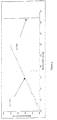
- FIG. 2 represents an abacus making it possible to read the maximum value of the appropriate external diameter: as a function of the time of electrical relaxation in s (abscissa axis) of the liquid considered, the maximum value of the outside diameter of the capillary in m (ordinate axis) is read on the straight line if it is a low-viscosity liquid, on the dashed right if it is a liquid with a high viscosity.
- the terms "low” and "high” viscosity are understood in accordance with the notions commonly accepted by those skilled in the art.
- low viscosity means a viscosity of about 1mPa.s
- high viscosity means a viscosity greater than about two orders of magnitude (about the order of 100 mPa.s approximately).
- the outer diameter values of the capillary 1 range from 0.324 to 1.8 mm.
- the results of this example were obtained with capillaries placed on a conductive support disposed perpendicularly to the axis of the capillary.
- each couple (outside diameter - inside diameter) is tested with different liquids with surface tension greater than 0.055 N / m, and remarkably greater than 0.065 N / m at ambient temperature (liquids ranging from ultrapure water (conductivity 10 ⁇ S / m ⁇ q 70 ⁇ s) with water doped with conducting salts (conductivity 1000 ⁇ S / m, ⁇ q 7.10 -7 s)).
- the entire device according to the invention is placed in the air and at atmospheric pressure, a positive DC voltage of between +1 and + 30 kV is applied, and said device is supplied with liquid.
- the LDA 7 and oscilloscope 8 systems make it possible to observe the achievement of a stable or unstable HDPE (absence or presence of pulse pulse regime). The probability of obtaining for all the tested liquids a stable HDPE for each pair D ext / D int tested is then calculated.
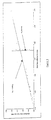
- FIG. 3 shows, for different pairs of values (inner diameter of the capillary 1, outer diameter of the capillary 1), these HDPE results obtained with a liquid whose conductivity is 100 ⁇ S / m: the symbol + indicates the achievement of a stable HDPE (absence of pulse pulse regime), that is to say the obtaining of a stable "cone-jet-glow” mode with a probability equal to 1; the symbol - indicates obtaining an unstable HDPE (presence of a pulse pulse regime), that is to say obtaining an unstable mode ("cone-jet-glow” non-permanent), and therefore with a probability less than 1.
- Tables 1 and 2 above, as well as FIGS. 3 and 4 show that, if the values of D ext and D int correspond to an appropriate relation, a HDPE without pulse pulse regime can be obtained, in the air and at atmospheric pressure, for a liquid with a surface tension greater than 0.055 N / m, and remarkably greater than 0.065 N / m, with a probability equal to 1.
- a suitable relation can be calculated and read in Figure 3 (conductivity liquid of 100 ⁇ S / m) and Figure 4 (liquid conductivity of 1000 ⁇ S / m) as being: report D ext D int capillary 1 greater than about 1.5697. The same is done on the remaining D ext ranges (up to maximum D ext ).
Landscapes
- Electrostatic Spraying Apparatus (AREA)
- Physical Or Chemical Processes And Apparatus (AREA)
- Formation Of Various Coating Films On Cathode Ray Tubes And Lamps (AREA)
- Electrotherapy Devices (AREA)
- Agricultural Chemicals And Associated Chemicals (AREA)
- Containers And Packaging Bodies Having A Special Means To Remove Contents (AREA)
- Photoreceptors In Electrophotography (AREA)
- Coating By Spraying Or Casting (AREA)
- Acyclic And Carbocyclic Compounds In Medicinal Compositions (AREA)
- Organic Low-Molecular-Weight Compounds And Preparation Thereof (AREA)
- Cosmetics (AREA)
Applications Claiming Priority (3)
| Application Number | Priority Date | Filing Date | Title |
|---|---|---|---|
| FR9803842A FR2776538B1 (fr) | 1998-03-27 | 1998-03-27 | Moyens de pulverisation electrohydrodynamique |
| FR9803842 | 1998-03-27 | ||
| PCT/FR1999/000730 WO1999049981A1 (fr) | 1998-03-27 | 1999-03-29 | Moyens de pulverisation electrohydrodynamique |
Publications (3)
| Publication Number | Publication Date |
|---|---|
| EP1064100A1 EP1064100A1 (fr) | 2001-01-03 |
| EP1064100B1 EP1064100B1 (fr) | 2006-06-21 |
| EP1064100B9 true EP1064100B9 (fr) | 2006-10-11 |
Family
ID=9524593
Family Applications (1)
| Application Number | Title | Priority Date | Filing Date |
|---|---|---|---|
| EP99910454A Expired - Lifetime EP1064100B9 (fr) | 1998-03-27 | 1999-03-29 | Moyens de pulverisation electrohydrodynamique |
Country Status (9)
| Country | Link |
|---|---|
| US (1) | US6679441B1 (da) |
| EP (1) | EP1064100B9 (da) |
| JP (1) | JP4491675B2 (da) |
| AT (1) | ATE330707T1 (da) |
| AU (1) | AU2940599A (da) |
| DE (1) | DE69932042T2 (da) |
| DK (1) | DK1064100T3 (da) |
| FR (1) | FR2776538B1 (da) |
| WO (1) | WO1999049981A1 (da) |
Families Citing this family (60)
| Publication number | Priority date | Publication date | Assignee | Title |
|---|---|---|---|---|
| US4787585A (en) * | 1987-06-11 | 1988-11-29 | Wang Laboratories, Inc. | Adapter support |
| US6397838B1 (en) * | 1998-12-23 | 2002-06-04 | Battelle Pulmonary Therapeutics, Inc. | Pulmonary aerosol delivery device and method |
| ATE274955T1 (de) * | 1999-05-03 | 2004-09-15 | Battelle Memorial Institute | Arzneizusammensetzungen zur aerosolbildung und zu inhalationszwecken |
| KR100455718B1 (ko) * | 2000-01-28 | 2004-11-08 | 안강호 | 분무입자의 유도가 가능한 전기수력학적 분사장치 |
| DE60142043D1 (de) | 2000-04-03 | 2010-06-17 | Battelle Memorial Inst Columbu | Ausgabevorrichtungen und flüssigformulierungen |
| JP2004526674A (ja) | 2000-12-01 | 2004-09-02 | バテル・メモリアル・インスティテュート | 液体処方物中における生体分子の安定化のための方法 |
| ES2180405B1 (es) * | 2001-01-31 | 2004-01-16 | Univ Sevilla | Dispositivo y procedimiento para producir chorros liquidos compuestos multicomponentes estacionarios y capsulas multicomponente y/o multicapa de tamaño micro y nanometrico. |
| DE60320383D1 (de) * | 2002-02-04 | 2008-05-29 | Univ Sevilla | Vorrichtung zur erzeugung kapillarer strahlen und mikro- und nanometerteilchen |
| ES2199048B1 (es) * | 2002-02-04 | 2005-06-01 | Universidad De Sevilla | Dispositivo multidispositivo y procedimiento para la produccion de chorros capilares y particulas micro y nanometricos. |
| ES2239861B1 (es) * | 2002-04-05 | 2006-11-16 | Universidad De Sevilla | Dispositivo y procedimiento para producir electrosprays de liquidos conductores en el seno de liquidos dielectricos y emulsiones multicomponentes. |
| GB0307403D0 (en) | 2003-03-31 | 2003-05-07 | Medical Res Council | Selection by compartmentalised screening |
| US20060078893A1 (en) * | 2004-10-12 | 2006-04-13 | Medical Research Council | Compartmentalised combinatorial chemistry by microfluidic control |
| GB0307428D0 (en) * | 2003-03-31 | 2003-05-07 | Medical Res Council | Compartmentalised combinatorial chemistry |
| US20050221339A1 (en) * | 2004-03-31 | 2005-10-06 | Medical Research Council Harvard University | Compartmentalised screening by microfluidic control |
| FR2872068B1 (fr) | 2004-06-28 | 2006-10-27 | Centre Nat Rech Scient Cnrse | Procede et dispositif pour le depot de couches minces par pulverisation electrohydrodynamique, notamment en post-decharge |
| US7326043B2 (en) * | 2004-06-29 | 2008-02-05 | Cornell Research Foundation, Inc. | Apparatus and method for elevated temperature electrospinning |
| US7968287B2 (en) * | 2004-10-08 | 2011-06-28 | Medical Research Council Harvard University | In vitro evolution in microfluidic systems |
| US7083854B1 (en) * | 2005-05-10 | 2006-08-01 | Cornell Research Foundation, Inc. | Fibers from polymer nanoclay nanocomposites by electrospinning |
| US20070017505A1 (en) * | 2005-07-15 | 2007-01-25 | Lipp Brian A | Dispensing device and method |
| JP4674541B2 (ja) * | 2005-12-22 | 2011-04-20 | パナソニック電工株式会社 | 静電霧化装置及び静電霧化装置を備えた食品保管庫 |
| WO2007081385A2 (en) | 2006-01-11 | 2007-07-19 | Raindance Technologies, Inc. | Microfluidic devices and methods of use in the formation and control of nanoreactors |
| JP4645501B2 (ja) * | 2006-03-29 | 2011-03-09 | パナソニック電工株式会社 | 静電霧化装置 |
| US8297959B2 (en) * | 2006-05-03 | 2012-10-30 | Terapia Celular, Ln, Inc. | Systems for producing multilayered particles, fibers and sprays and methods for administering the same |
| EP2530167A1 (en) | 2006-05-11 | 2012-12-05 | Raindance Technologies, Inc. | Microfluidic Devices |
| US9562837B2 (en) | 2006-05-11 | 2017-02-07 | Raindance Technologies, Inc. | Systems for handling microfludic droplets |
| EP2077912B1 (en) | 2006-08-07 | 2019-03-27 | The President and Fellows of Harvard College | Fluorocarbon emulsion stabilizing surfactants |
| WO2008097559A2 (en) | 2007-02-06 | 2008-08-14 | Brandeis University | Manipulation of fluids and reactions in microfluidic systems |
| US8592221B2 (en) | 2007-04-19 | 2013-11-26 | Brandeis University | Manipulation of fluids, fluid components and reactions in microfluidic systems |
| FR2924349B1 (fr) | 2007-12-03 | 2010-01-01 | Dbv Tech | Methode de desensibilitation aux allergenes |
| FR2926466B1 (fr) * | 2008-01-23 | 2010-11-12 | Dbv Tech | Procede de fabrication de patchs par electrospray |
| JP5190280B2 (ja) * | 2008-02-29 | 2013-04-24 | オリジン電気株式会社 | 液体塗布装置及び液体塗布方法 |
| US20090314861A1 (en) * | 2008-06-18 | 2009-12-24 | Jaan Noolandi | Fluid ejection using multiple voltage pulses and removable modules |
| US12038438B2 (en) | 2008-07-18 | 2024-07-16 | Bio-Rad Laboratories, Inc. | Enzyme quantification |
| EP4047367A1 (en) | 2008-07-18 | 2022-08-24 | Bio-Rad Laboratories, Inc. | Method for detecting target analytes with droplet libraries |
| WO2010111231A1 (en) | 2009-03-23 | 2010-09-30 | Raindance Technologies, Inc. | Manipulation of microfluidic droplets |
| US10520500B2 (en) | 2009-10-09 | 2019-12-31 | Abdeslam El Harrak | Labelled silica-based nanomaterial with enhanced properties and uses thereof |
| US10837883B2 (en) | 2009-12-23 | 2020-11-17 | Bio-Rad Laboratories, Inc. | Microfluidic systems and methods for reducing the exchange of molecules between droplets |
| US10351905B2 (en) | 2010-02-12 | 2019-07-16 | Bio-Rad Laboratories, Inc. | Digital analyte analysis |
| US9399797B2 (en) | 2010-02-12 | 2016-07-26 | Raindance Technologies, Inc. | Digital analyte analysis |
| EP4484577A3 (en) | 2010-02-12 | 2025-03-26 | Bio-Rad Laboratories, Inc. | Digital analyte analysis |
| US9366632B2 (en) | 2010-02-12 | 2016-06-14 | Raindance Technologies, Inc. | Digital analyte analysis |
| US9562897B2 (en) | 2010-09-30 | 2017-02-07 | Raindance Technologies, Inc. | Sandwich assays in droplets |
| AU2011265562A1 (en) | 2011-01-12 | 2012-07-26 | Sumitomo Chemical Company, Limited | Method of controlling harmful arthropod, composition, and electrostatic spray device |
| EP3412778A1 (en) | 2011-02-11 | 2018-12-12 | Raindance Technologies, Inc. | Methods for forming mixed droplets |
| WO2012112804A1 (en) | 2011-02-18 | 2012-08-23 | Raindance Technoligies, Inc. | Compositions and methods for molecular labeling |
| EP3216872B1 (en) | 2011-06-02 | 2020-04-01 | Bio-Rad Laboratories, Inc. | Enzyme quantification |
| US8841071B2 (en) | 2011-06-02 | 2014-09-23 | Raindance Technologies, Inc. | Sample multiplexing |
| US8658430B2 (en) | 2011-07-20 | 2014-02-25 | Raindance Technologies, Inc. | Manipulating droplet size |
| US9589852B2 (en) * | 2013-07-22 | 2017-03-07 | Cree, Inc. | Electrostatic phosphor coating systems and methods for light emitting structures and packaged light emitting diodes including phosphor coating |
| US11901041B2 (en) | 2013-10-04 | 2024-02-13 | Bio-Rad Laboratories, Inc. | Digital analysis of nucleic acid modification |
| US9944977B2 (en) | 2013-12-12 | 2018-04-17 | Raindance Technologies, Inc. | Distinguishing rare variations in a nucleic acid sequence from a sample |
| WO2015103367A1 (en) | 2013-12-31 | 2015-07-09 | Raindance Technologies, Inc. | System and method for detection of rna species |
| US9925547B2 (en) * | 2014-08-26 | 2018-03-27 | Tsi, Incorporated | Electrospray with soft X-ray neutralizer |
| DE112014005031B4 (de) * | 2014-11-13 | 2019-04-25 | Shindengen Electric Manufacturing Co., Ltd. | Verfahren zur Herstellung eines Halbleiter-Bauelements und Vorrichtung zur Herstellung einer Glasschicht |
| US10647981B1 (en) | 2015-09-08 | 2020-05-12 | Bio-Rad Laboratories, Inc. | Nucleic acid library generation methods and compositions |
| JP6528333B2 (ja) * | 2016-08-01 | 2019-06-12 | パナソニックIpマネジメント株式会社 | 静電霧化装置 |
| CN106563322B (zh) * | 2016-10-31 | 2019-01-29 | 重庆市南川区庆岩福利碱厂 | 锅炉水膜除尘装置 |
| CN108905582A (zh) * | 2018-08-30 | 2018-11-30 | 肇庆市高要区华锋电子铝箔有限公司 | 一种喷雾环及酸雾净化塔 |
| EP3760194A1 (en) | 2019-07-01 | 2021-01-06 | DBV Technologies | Method of depositing a substance on a substrate |
| CN112121578B (zh) * | 2020-09-21 | 2021-06-18 | 熙诚环保科技(苏州)有限公司 | 一种高效型垃圾处理用废气喷淋净化塔 |
Family Cites Families (10)
| Publication number | Priority date | Publication date | Assignee | Title |
|---|---|---|---|---|
| US4264641A (en) * | 1977-03-17 | 1981-04-28 | Phrasor Technology Inc. | Electrohydrodynamic spraying to produce ultrafine particles |
| USRE30479E (en) * | 1978-05-17 | 1981-01-13 | Trw Inc. | Method of removing particles and fluids from a gas stream by charged droplets |
| US4335419A (en) * | 1980-10-20 | 1982-06-15 | Hastings Edward E | Insulated dust control apparatus for use in an explosive environment |
| GB8604328D0 (en) * | 1986-02-21 | 1986-03-26 | Ici Plc | Producing spray of droplets of liquid |
| US4669671A (en) * | 1986-03-06 | 1987-06-02 | Hastings Edward E | Pollutant suppression device |
| US4658269A (en) * | 1986-06-02 | 1987-04-14 | Xerox Corporation | Ink jet printer with integral electrohydrodynamic electrodes and nozzle plate |
| US4748043A (en) * | 1986-08-29 | 1988-05-31 | Minnesota Mining And Manufacturing Company | Electrospray coating process |
| US6105571A (en) * | 1992-12-22 | 2000-08-22 | Electrosols, Ltd. | Dispensing device |
| GB9226717D0 (en) * | 1992-12-22 | 1993-02-17 | Coffee Ronald A | Induction-operated electro-hydrodynamic spray device with means of modifying droplet trajectories |
| GB9406255D0 (en) * | 1994-03-29 | 1994-05-18 | Electrosols Ltd | Dispensing device |
-
1998
- 1998-03-27 FR FR9803842A patent/FR2776538B1/fr not_active Expired - Fee Related
-
1999
- 1999-03-29 AU AU29405/99A patent/AU2940599A/en not_active Abandoned
- 1999-03-29 JP JP2000540939A patent/JP4491675B2/ja not_active Expired - Fee Related
- 1999-03-29 EP EP99910454A patent/EP1064100B9/fr not_active Expired - Lifetime
- 1999-03-29 DE DE69932042T patent/DE69932042T2/de not_active Expired - Lifetime
- 1999-03-29 WO PCT/FR1999/000730 patent/WO1999049981A1/fr not_active Ceased
- 1999-03-29 AT AT99910454T patent/ATE330707T1/de not_active IP Right Cessation
- 1999-03-29 DK DK99910454T patent/DK1064100T3/da active
- 1999-08-29 US US09/647,172 patent/US6679441B1/en not_active Expired - Fee Related
Also Published As
| Publication number | Publication date |
|---|---|
| JP2002509794A (ja) | 2002-04-02 |
| JP4491675B2 (ja) | 2010-06-30 |
| US6679441B1 (en) | 2004-01-20 |
| FR2776538A1 (fr) | 1999-10-01 |
| DE69932042D1 (de) | 2006-08-03 |
| EP1064100A1 (fr) | 2001-01-03 |
| DE69932042T2 (de) | 2007-01-11 |
| AU2940599A (en) | 1999-10-18 |
| EP1064100B1 (fr) | 2006-06-21 |
| DK1064100T3 (da) | 2006-12-27 |
| FR2776538B1 (fr) | 2000-07-21 |
| ATE330707T1 (de) | 2006-07-15 |
| WO1999049981A1 (fr) | 1999-10-07 |
Similar Documents
| Publication | Publication Date | Title |
|---|---|---|
| EP1064100B9 (fr) | Moyens de pulverisation electrohydrodynamique | |
| Jaworek et al. | Corona discharge in electrospraying | |
| US4508265A (en) | Method for spray combination of liquids and apparatus therefor | |
| CA1244299A (en) | Spraying apparatus | |
| US6479077B1 (en) | Method of manufacturing powder particles | |
| Jones et al. | The production of charged monodisperse fuel droplets by electrical dispersion | |
| US6207239B1 (en) | Plasma enhanced chemical deposition of conjugated polymer | |
| US6224948B1 (en) | Plasma enhanced chemical deposition with low vapor pressure compounds | |
| Marchewicz et al. | Induction charging of water spray produced by pressure atomizer | |
| WO2006010845A1 (fr) | Procede et dispositif pour le depot de couches minces par pulverisation electrohydrodynamique, notamment en post-decharge | |
| FR2737138A1 (fr) | Procede et dispositif de pulverisation d'un produit liquide | |
| EP2656921B1 (fr) | Dispositif éléctrostatique de collecte de particules en suspension dans un milieu gazeux | |
| US20060093737A1 (en) | Method and apparatus for generating charged particles for deposition on a surface | |
| EP1476588B1 (fr) | Procede de nettoyage de la surface d un materiau enduit d une substance organique, generateur et dispositif de mise en oeuvre | |
| Wang et al. | Plasma decoloration of dye using dielectric barrier discharges with earthed spraying water electrodes | |
| Sato | Formation of uniformly sized liquid droplets using spinning disk under applied electrostatic field | |
| Elele et al. | Detection of a dynamic cone-shaped meniscus on the surface of fluids in electric fields | |
| CH642870A5 (fr) | Procede et dispositif de separation de particules en suspension dans un gaz. | |
| Meesters et al. | A (sub-) micron aerosol generator, using a high electric field | |
| WO2011141184A1 (de) | Plasmagenerator sowie verfahren zur erzeugung und anwendung eines ionisierten gases | |
| EP0437383A1 (fr) | Procédé et dispositif de peinture électrostatique sur pièces plastiques | |
| EP3517214A1 (en) | A spray surface treatment device | |
| Kobara et al. | Features and advantages of electrospray in an insulating liquid | |
| EP1512469B1 (fr) | Procédé et installation pour la lubrification de cylindres de laminage | |
| EP1538418A1 (fr) | Système étanche de production de flammes pour le spectacle |
Legal Events
| Date | Code | Title | Description |
|---|---|---|---|
| PUAI | Public reference made under article 153(3) epc to a published international application that has entered the european phase |
Free format text: ORIGINAL CODE: 0009012 |
|
| 17P | Request for examination filed |
Effective date: 20000814 |
|
| AK | Designated contracting states |
Kind code of ref document: A1 Designated state(s): AT BE CH CY DE DK ES FI FR GB GR IE IT LI LU MC NL PT SE |
|
| 17Q | First examination report despatched |
Effective date: 20030319 |
|
| GRAP | Despatch of communication of intention to grant a patent |
Free format text: ORIGINAL CODE: EPIDOSNIGR1 |
|
| GRAS | Grant fee paid |
Free format text: ORIGINAL CODE: EPIDOSNIGR3 |
|
| GRAA | (expected) grant |
Free format text: ORIGINAL CODE: 0009210 |
|
| AK | Designated contracting states |
Kind code of ref document: B1 Designated state(s): AT BE CH CY DE DK ES FI FR GB GR IE IT LI LU MC NL PT SE |
|
| PG25 | Lapsed in a contracting state [announced via postgrant information from national office to epo] |
Ref country code: NL Free format text: LAPSE BECAUSE OF FAILURE TO SUBMIT A TRANSLATION OF THE DESCRIPTION OR TO PAY THE FEE WITHIN THE PRESCRIBED TIME-LIMIT Effective date: 20060621 Ref country code: IT Free format text: LAPSE BECAUSE OF FAILURE TO SUBMIT A TRANSLATION OF THE DESCRIPTION OR TO PAY THE FEE WITHIN THE PRESCRIBED TIME-LIMIT;WARNING: LAPSES OF ITALIAN PATENTS WITH EFFECTIVE DATE BEFORE 2007 MAY HAVE OCCURRED AT ANY TIME BEFORE 2007. THE CORRECT EFFECTIVE DATE MAY BE DIFFERENT FROM THE ONE RECORDED. Effective date: 20060621 Ref country code: AT Free format text: LAPSE BECAUSE OF FAILURE TO SUBMIT A TRANSLATION OF THE DESCRIPTION OR TO PAY THE FEE WITHIN THE PRESCRIBED TIME-LIMIT Effective date: 20060621 |
|
| REG | Reference to a national code |
Ref country code: GB Ref legal event code: FG4D Free format text: NOT ENGLISH |
|
| REG | Reference to a national code |
Ref country code: CH Ref legal event code: EP |
|
| REG | Reference to a national code |
Ref country code: IE Ref legal event code: FG4D Free format text: LANGUAGE OF EP DOCUMENT: FRENCH |
|
| REF | Corresponds to: |
Ref document number: 69932042 Country of ref document: DE Date of ref document: 20060803 Kind code of ref document: P |
|
| PG25 | Lapsed in a contracting state [announced via postgrant information from national office to epo] |
Ref country code: ES Free format text: LAPSE BECAUSE OF FAILURE TO SUBMIT A TRANSLATION OF THE DESCRIPTION OR TO PAY THE FEE WITHIN THE PRESCRIBED TIME-LIMIT Effective date: 20061002 |
|
| REG | Reference to a national code |
Ref country code: SE Ref legal event code: TRGR |
|
| PG25 | Lapsed in a contracting state [announced via postgrant information from national office to epo] |
Ref country code: PT Free format text: LAPSE BECAUSE OF FAILURE TO SUBMIT A TRANSLATION OF THE DESCRIPTION OR TO PAY THE FEE WITHIN THE PRESCRIBED TIME-LIMIT Effective date: 20061121 |
|
| NLV1 | Nl: lapsed or annulled due to failure to fulfill the requirements of art. 29p and 29m of the patents act | ||
| GBT | Gb: translation of ep patent filed (gb section 77(6)(a)/1977) |
Effective date: 20061116 |
|
| REG | Reference to a national code |
Ref country code: CH Ref legal event code: NV Representative=s name: ISLER & PEDRAZZINI AG |
|
| REG | Reference to a national code |
Ref country code: DK Ref legal event code: T3 |
|
| PLBE | No opposition filed within time limit |
Free format text: ORIGINAL CODE: 0009261 |
|
| STAA | Information on the status of an ep patent application or granted ep patent |
Free format text: STATUS: NO OPPOSITION FILED WITHIN TIME LIMIT |
|
| 26N | No opposition filed |
Effective date: 20070322 |
|
| REG | Reference to a national code |
Ref country code: CH Ref legal event code: PCAR Free format text: ISLER & PEDRAZZINI AG;POSTFACH 1772;8027 ZUERICH (CH) |
|
| BERE | Be: lapsed |
Owner name: CENTRE NATIONAL DE LA RECHERCHE SCIENTIFIQUE (CNR Effective date: 20070331 |
|
| PG25 | Lapsed in a contracting state [announced via postgrant information from national office to epo] |
Ref country code: BE Free format text: LAPSE BECAUSE OF NON-PAYMENT OF DUE FEES Effective date: 20070331 |
|
| PG25 | Lapsed in a contracting state [announced via postgrant information from national office to epo] |
Ref country code: MC Free format text: LAPSE BECAUSE OF NON-PAYMENT OF DUE FEES Effective date: 20070331 |
|
| PG25 | Lapsed in a contracting state [announced via postgrant information from national office to epo] |
Ref country code: GR Free format text: LAPSE BECAUSE OF FAILURE TO SUBMIT A TRANSLATION OF THE DESCRIPTION OR TO PAY THE FEE WITHIN THE PRESCRIBED TIME-LIMIT Effective date: 20060922 |
|
| PG25 | Lapsed in a contracting state [announced via postgrant information from national office to epo] |
Ref country code: LU Free format text: LAPSE BECAUSE OF NON-PAYMENT OF DUE FEES Effective date: 20070329 Ref country code: CY Free format text: LAPSE BECAUSE OF FAILURE TO SUBMIT A TRANSLATION OF THE DESCRIPTION OR TO PAY THE FEE WITHIN THE PRESCRIBED TIME-LIMIT Effective date: 20060621 |
|
| PGFP | Annual fee paid to national office [announced via postgrant information from national office to epo] |
Ref country code: IE Payment date: 20110222 Year of fee payment: 13 Ref country code: DK Payment date: 20110218 Year of fee payment: 13 |
|
| PGFP | Annual fee paid to national office [announced via postgrant information from national office to epo] |
Ref country code: FI Payment date: 20110221 Year of fee payment: 13 Ref country code: CH Payment date: 20110222 Year of fee payment: 13 Ref country code: SE Payment date: 20110222 Year of fee payment: 13 |
|
| PGFP | Annual fee paid to national office [announced via postgrant information from national office to epo] |
Ref country code: DE Payment date: 20110308 Year of fee payment: 13 Ref country code: GB Payment date: 20110224 Year of fee payment: 13 Ref country code: FR Payment date: 20110412 Year of fee payment: 13 |
|
| REG | Reference to a national code |
Ref country code: SE Ref legal event code: EUG |
|
| PG25 | Lapsed in a contracting state [announced via postgrant information from national office to epo] |
Ref country code: FI Free format text: LAPSE BECAUSE OF NON-PAYMENT OF DUE FEES Effective date: 20120329 Ref country code: SE Free format text: LAPSE BECAUSE OF NON-PAYMENT OF DUE FEES Effective date: 20120330 |
|
| REG | Reference to a national code |
Ref country code: CH Ref legal event code: PL |
|
| REG | Reference to a national code |
Ref country code: DK Ref legal event code: EBP |
|
| GBPC | Gb: european patent ceased through non-payment of renewal fee |
Effective date: 20120329 |
|
| REG | Reference to a national code |
Ref country code: FR Ref legal event code: ST Effective date: 20121130 |
|
| REG | Reference to a national code |
Ref country code: IE Ref legal event code: MM4A |
|
| REG | Reference to a national code |
Ref country code: DE Ref legal event code: R119 Ref document number: 69932042 Country of ref document: DE Effective date: 20121002 |
|
| PG25 | Lapsed in a contracting state [announced via postgrant information from national office to epo] |
Ref country code: GB Free format text: LAPSE BECAUSE OF NON-PAYMENT OF DUE FEES Effective date: 20120329 Ref country code: CH Free format text: LAPSE BECAUSE OF NON-PAYMENT OF DUE FEES Effective date: 20120331 Ref country code: FR Free format text: LAPSE BECAUSE OF NON-PAYMENT OF DUE FEES Effective date: 20120402 Ref country code: LI Free format text: LAPSE BECAUSE OF NON-PAYMENT OF DUE FEES Effective date: 20120331 Ref country code: IE Free format text: LAPSE BECAUSE OF NON-PAYMENT OF DUE FEES Effective date: 20120329 |
|
| PG25 | Lapsed in a contracting state [announced via postgrant information from national office to epo] |
Ref country code: DK Free format text: LAPSE BECAUSE OF NON-PAYMENT OF DUE FEES Effective date: 20120331 |
|
| PG25 | Lapsed in a contracting state [announced via postgrant information from national office to epo] |
Ref country code: DE Free format text: LAPSE BECAUSE OF NON-PAYMENT OF DUE FEES Effective date: 20121002 |