EP1064111B1 - Procede permettant de commander, de surveiller et de controler une operation de formage d'une machine de formage, notamment d'une riveteuse - Google Patents
Procede permettant de commander, de surveiller et de controler une operation de formage d'une machine de formage, notamment d'une riveteuse Download PDFInfo
- Publication number
- EP1064111B1 EP1064111B1 EP99907589A EP99907589A EP1064111B1 EP 1064111 B1 EP1064111 B1 EP 1064111B1 EP 99907589 A EP99907589 A EP 99907589A EP 99907589 A EP99907589 A EP 99907589A EP 1064111 B1 EP1064111 B1 EP 1064111B1
- Authority
- EP
- European Patent Office
- Prior art keywords
- reshaping
- beginning
- pressure
- force
- piston chamber
- Prior art date
- Legal status (The legal status is an assumption and is not a legal conclusion. Google has not performed a legal analysis and makes no representation as to the accuracy of the status listed.)
- Expired - Lifetime
Links
- 238000000034 method Methods 0.000 title claims description 48
- 238000012544 monitoring process Methods 0.000 title claims description 5
- 230000008569 process Effects 0.000 claims description 26
- 230000008859 change Effects 0.000 claims description 20
- 230000002950 deficient Effects 0.000 claims description 6
- 238000001514 detection method Methods 0.000 claims description 5
- 238000006073 displacement reaction Methods 0.000 claims description 5
- 238000009423 ventilation Methods 0.000 claims 4
- 238000004519 manufacturing process Methods 0.000 description 4
- 239000000463 material Substances 0.000 description 4
- 230000008901 benefit Effects 0.000 description 3
- 230000001276 controlling effect Effects 0.000 description 2
- 238000002474 experimental method Methods 0.000 description 2
- XEEYBQQBJWHFJM-UHFFFAOYSA-N Iron Chemical compound [Fe] XEEYBQQBJWHFJM-UHFFFAOYSA-N 0.000 description 1
- 230000009471 action Effects 0.000 description 1
- 238000009530 blood pressure measurement Methods 0.000 description 1
- 230000007547 defect Effects 0.000 description 1
- 239000012530 fluid Substances 0.000 description 1
- 238000003908 quality control method Methods 0.000 description 1
- 230000009467 reduction Effects 0.000 description 1
- 230000001105 regulatory effect Effects 0.000 description 1
- 238000012552 review Methods 0.000 description 1
- 238000005070 sampling Methods 0.000 description 1
- 238000012795 verification Methods 0.000 description 1
Images

Classifications
-
- B—PERFORMING OPERATIONS; TRANSPORTING
- B21—MECHANICAL METAL-WORKING WITHOUT ESSENTIALLY REMOVING MATERIAL; PUNCHING METAL
- B21J—FORGING; HAMMERING; PRESSING METAL; RIVETING; FORGE FURNACES
- B21J15/00—Riveting
- B21J15/10—Riveting machines
- B21J15/28—Control devices specially adapted to riveting machines not restricted to one of the preceding subgroups
- B21J15/285—Control devices specially adapted to riveting machines not restricted to one of the preceding subgroups for controlling the rivet upset cycle
-
- B—PERFORMING OPERATIONS; TRANSPORTING
- B21—MECHANICAL METAL-WORKING WITHOUT ESSENTIALLY REMOVING MATERIAL; PUNCHING METAL
- B21J—FORGING; HAMMERING; PRESSING METAL; RIVETING; FORGE FURNACES
- B21J15/00—Riveting
- B21J15/10—Riveting machines
- B21J15/12—Riveting machines with tools or tool parts having a movement additional to the feed movement, e.g. spin
-
- B—PERFORMING OPERATIONS; TRANSPORTING
- B21—MECHANICAL METAL-WORKING WITHOUT ESSENTIALLY REMOVING MATERIAL; PUNCHING METAL
- B21J—FORGING; HAMMERING; PRESSING METAL; RIVETING; FORGE FURNACES
- B21J9/00—Forging presses
- B21J9/10—Drives for forging presses
- B21J9/20—Control devices specially adapted to forging presses not restricted to one of the preceding subgroups
Definitions
- the present invention relates to a method for Controlling, monitoring and checking a forming process a forming machine, in particular a riveting machine, on one Workpiece by means of a piston, which against the Workpiece is moved, with an upper piston surface and / or a lower piston surface for moving the piston is pressurized and a forming machine to carry out the above Process.
- riveting machines are in the stand known in the most varied of forms and designs and common. They are primarily used to mechanical mechanical material deformations, in particular also rivets. Such should. Machines can be integrated into automation processes can. Essentially, this is the Production of riveted joints using a riveting machine cold deformations, because two Parts can be connected together.
- EP 0 699 490 A1 describes a device for Verification of material deformations known, being about two different displacement sensor arrangements and via push buttons if necessary, a deviation is determined.
- the disadvantage here is that such a device is complex and complex manufactured and no exact determination of a rivet start is possible.
- DE 37 15 905 C2 describes a method for mechanical production of riveted joints and a riveting machine for performing the method known, at which opposes a striker from a given zero position a workpiece is moved. This shifting to one Workpiece is made with a measuring force that is less than the force required to deform the rivet. The feed distance of the striker caused by the measuring force is measured and is used as an actual value with a setpoint compared. The disadvantage of this is that not with full Feed force can be applied to the rivet. A Monitoring of the complete riveting process is not here possible.
- EP 0 549 793 A1 describes a method for plastic deformation of workpieces, the Feed rate of the striker is controllable.
- the present invention is based on the object Procedures for controlling, monitoring and reviewing a Forming process and to create a forming machine at which a determination of a start of forming or Rivet start is exactly possible. After that, exact Conclusions about faulty forming processes may be possible. Furthermore, significant manufacturing costs should such a forming machine can be reduced. It is said to be very easy and simple with increasing the forming quality control.
- the solution to this task is that when the Piston, especially the striker, on the workpiece of Start of forming, especially start of riveting, by changing the Forming force is determined, this forming force with With the help of a differential pressure measurement through determined pressure in the upper piston chamber minus the determined pressure in the lower Piston space is calculated.
- the sensor element should preferably be in the machine housing provided near the upper and / or lower piston space his. This is connected to a control device, which evaluates the data.
- the piston permanently with full feed and if necessary constant feed force when forming on the workpiece can be driven. Only the pressure change immediately when the riveting tool hits the Workpiece displayed and can via a distance measuring device then a predefined path, in particular a forming path continue until the predetermined path is reached within a certain time. on the other hand can also with a given feed or forming force the piston against the workpiece for a certain time be moved until after a certain forming or Comparison time, the forming is carried out as desired.
- predetermined comparison parameters which, for example, by Experiment can be determined, can be exactly determine whether the forming has been carried out as desired. It can be determined exactly, for example, whether the rivet was sufficient or not a rivet at all, or whether the forming time or the forming path was carried out exactly. This is through the Determination of the exact start of forming possible.
- the present invention is a method as well as a forming machine, with which very exactly one rivet start or forming start can be determined can.
- the time for a specific forming path as Comparison criterion can be used to make a statement faulty or non-faulty forming receive.
- the time is predetermined and the forming path covered during this time as Comparison criterion for determining a forming condition is used. This ensures that too an automated forming process is constantly monitored and can be controlled.
- Another advantage is that a very precise error detection or a determination of the cause of the error is always preferred by two comparison variables with a given one Parameter is made to rule out two Mistakes together with reverse value each other compensate and thus a detection of an error prevent.
- the determinable forming work per unit of time also leaves an exact assessment of the riveting process and in particular an exact conclusion on the strength properties of the formed workpiece.
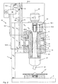
- Figure 1 is a forming machine, in particular Riveting machine R shown, the main components a conventional riveting machine, as in the EP 0 699 490 A1 is shown. It is explicitly based on referred to this prior art because essentially there all the components of a conventional riveting machine are described in detail. Another description the individual components are therefore dispensed with.
- a forming machine R only has a dashed line here indicated machine frame 1, which only one has indicated vertical support arm, in which preferably adjoins a support surface 2 at right angles.
- the support surface 2 carries the workpieces to be machined 27. These are not numbered in detail here.
- To the Machine frame 1 and especially on the vertical Carrying arm is a machine housing 3, which in Interior is hollow.
- a machine housing 3 In the machine housing 3 is a preferably hollow slidable pneumatic piston 4 arranged. Protrudes from the piston 4 preferably a projecting flange 5 towards the outside, which is guided in a cavity 6 of the machine housing 3 is.
- the cavity 6 is through the protruding flange 5 in an upper piston chamber 7 and lower piston chamber 8 divided.
- the projecting flange 5 accordingly has a upper piston chamber 7 facing upper piston surface 9 and a lower piston surface 10.
- a control valve 13, 14, in particular a throttle is used, the connecting lines 15.1, 15.2 with a Control device 16 is connected.
- Another Connection line 15.3 provides the connection between a drive motor 17, in particular an electric motor. This can also be designed as a hydraulic motor.
- the Electric motor drives a sleeve 18.1 in which changeable a projecting end 18.2 one Drive shaft 19 is mounted.
- the drive shaft 19 is via only indicated bearings in a cavity 20 of the Piston 4 rotatably mounted.
- the rivet head 21 also serves as a tool holder. This can, for example, as Riveting tools include a striker 22.
- a displacement measuring device 24 which, via a further connecting line 15.4 the control device 16 is connected.
- This Control device 16 takes over all regulations and Controls that operate the R required are.
- the data required for this can be obtained via a Computer 25 entered and during or after a Work process evaluated and output there. This is only an example here. In particular, can such a control device 16 into an existing one Production can be integrated in order to be fully automatic to operate the corresponding riveting machine R.
- a Sensor element 26.1 in the pressure line 11 and Sensor element 26.2 inserted into the vent line 12 is.
- the sensor elements 26.1, 26.2 are preferably close of the machine housing 3 in the pressure line 11 or Vent line 12 used.
- the sensor elements 26.1, 26.2 are also via connecting lines 15.5, 15.6 connected to the control device 16. It is important here also that the sensor elements 26.1, 26.2 between the Control valves 13, 14 and the machine housing 3 in the Pressure line 26.1 or vent line 26.2 used are.
- the sensor elements 26.1, 26.2 which are preferably as Pressure sensors, but also designed as a pressure transmitter are a very precise change in pressure in the Determine pressure line 11 or vent line 12 if when moving the piston 4 to a machined Workpiece 27 strikes. Immediately upon hitting the Workpiece 27, for example on a rivet, is in the pressure line 11 causes a pressure change that is beyond the Sensor elements 26.1, 26.2 and accordingly in the Vent line 26.2 is registered immediately. This Pressure change causes a start or an Displacement of the zero point can be calculated.
- the exact determination of the start of the rivet is required in order to for the optimum forming process, the exact forming path required to be able to determine. If the start of the rivet is known, it can via further method via the path measuring device 24 Forming path can be determined exactly. This can also be done by continuous procedure and timing can be possible.
- the advantage here is that an exact determination of the Forming begins by changing the pressure in the Sensor elements 26.1, 26.2 can be detected.
- a forming machine R 1 in particular a riveting machine, in which the sensor elements 26.3, 26.4 are inserted into an upper piston chamber 7 and a lower piston chamber 8.
- a throttle valve 29, which is adjustable, is preferably inserted into the vent line 12. This can be connected to the control device 16. As a result, the movement of the piston 4 can be damped in particular into a lower position. A hard impact of the piston after the downward movement is prevented by this throttle valve 29.
- the spindle advance can be regulated by means of the throttle valve 29, it also being possible to change the speed of the travel path of the spindle or of the piston 4.
- the sensor elements 26.3, 26.4 are over the Connection lines 15.7, 15.8 with the control device 16 connected.
- the change in pressure can precisely determine the start of the rivet but also the one calculated from the pressure change Forming force.
- the riveting results can be exactly check and determine.
- the forming path is known or specified, then through additional time comparison influence on the quality of the forming process. Will be within one certain time a certain predetermined way the reshaping or riveting is completed successful. So that a comparison is possible, for example Trial determined a certain time, a time tolerance measure set to a positive or negative riveting result detect.
Landscapes
- Engineering & Computer Science (AREA)
- Mechanical Engineering (AREA)
- Insertion Pins And Rivets (AREA)
- Presses And Accessory Devices Thereof (AREA)
- Control Of Presses (AREA)
Claims (19)
- Procédé de commande de surveillance et de contrôle d'une opération de formage d'une machine de formage notamment d'une riveteuse (R), sur une pièce (27) à l'aide d'un piston (4) déplacé contre la pièce (27), une surface supérieure de piston (9) et/ou une surface inférieure de piston (10) étant mises en pression pour déplacer le piston (4),
caractérisé en ce qu'
à l'arrivée du piston (4) en particulier de la bouterolle (22) sur la pièce (27), on définit le début du formage en particulier le début du rivetage à partir de la variation de la force du formage,
cette forme de formage se calculant par une mesure de différence pression entre la pression mesurée dans la chambre supérieure (7) du piston diminuée de la pression mesurée dans la chambre inférieure (8) du piston. - Procédé selon la revendication 1,
caractérisé en ce que
pendant tout le procédé de formage, par une mesure de différence de pression, on calcule la force de formage et/ou on affiche cette force, en la déterminant à partir de la pression régnant dans la chambre supérieure (7) du piston diminuée de la pression mesurée dans la chambre inférieure (8) du piston. - Procédé selon la revendication 1 ou 2,
caractérisé en ce qu'
on mesure la pression dans la chambre supérieure et dans la chambre inférieure (7, 8) du piston, directement dans ces chambres (7, 8). - Procédé selon la revendication 1,
caractérisé en ce qu'
on mesure directement la pression dans la chambre supérieure et celle dans la chambre inférieure du piston par une conduite de pression (11) et une conduite d'évacuation d'air (12). - Procédé selon au moins l'une quelconque des revendications 1 à 4,
caractérisé en ce qu'
on détermine la pression dans la chambre supérieure et celle dans la chambre inférieure du piston avec au moins un élément de capteur (26.1-26.4). - Procédé selon l'une quelconque des revendications 1 à 5,
caractérisé en ce qu'
en déterminant les variations de force et en définissant le début du formage, on détermine le début de la course de formage et/ou le début du temps de formage. - Procédé selon la revendication 6,
caractérisé en ce qu'
en déterminant le début du formage, on déplace le point zéro sur le début de la pièce. - Procédé selon la revendication 7,
caractérisé en ce qu'
en décalant et en déterminant le point zéro comme début du formage, on détermine la déformation pendant une durée prédéterminée et/ou une course de transformation prédéterminable et/ou une force de formage prédéterminable. - Procédé selon la revendication 8,
caractérisé en ce qu'
on détecte un formage le cas échéant défectueux tel d'un rivetage en déterminant une déviation de paramètres prédéterminés ou de relations entre ces paramètres tels que le début du formage, le temps du formage ou la force de formage pour chaque course de formage. - Procédé selon au moins l'une quelconque des revendications 5 à 9,
caractérisé en ce qu'
après avoir déterminé le début du formage ou le début du procédé, on parcourt une course de formage prédéterminée et on détermine le cas échéant un formage défectueux par une comparaison de temps. - Procédé selon au moins l'une quelconque des revendications 5 à 10,
caractérisé en ce qu'
après avoir déterminé un début de formage ou un début de procédé pour un temps déterminé, on détermine une course parcourue comme paramètre de comparaison pour déterminer un formage le cas échéant défectueux, le cas échéant dans la plage de tolérance de course. - Procédé selon au moins l'une quelconque des revendications 5 à 11,
caractérisé en ce qu'
après avoir déterminé un début de formage ou un début de procédé pour une course prédéterminée, on détermine une fenêtre de temps comme paramètre de comparaison pour déterminer un formage le cas échéant défectueux, le cas échéant situé dans la plage de tolérance des forces. - Procédé selon au moins l'une quelconque des revendications 5 à 12,
caractérisé en ce qu'
après avoir déterminé un début de formage, on détermine le travail de formage le cas échéant le travail de formage par unité de temps comme paramètre de compensation pour déterminer une transformation défectueuse le cas échéant située dans la plage de tolérance de travail. - Machine de formage notamment machine riveteuse comportant un piston (4) mobile suivant l'axe Z (23) qui peut être déplacé avec une pression contre une pièce (27) en étant guidé dans le corps (3) de la machine et le piston (4) en particulier sa bride (5) se déplace dans une cavité (6) subdivisée en une chambre supérieure (7) de piston et une chambre inférieure (8) de piston,
une conduite de pression (11) débouchant dans la chambre supérieure (7) et une conduite d'évacuation d'air (12) débouchant dans la chambre inférieure (8),
caractérisée en ce que
pour déterminer une pression différentielle et/ou une variation de force lors de l'arrivée du piston (4) en particulier de la bouterolle (22) sur une pièce (27), on associe à chaque conduite (11, 12) et/ou à chaque chambre de piston (7, 8) au moins un élément de capteur (26.1-26.4) avec lequel on détermine la différence de pression entre la pression dans la conduite de pression (11) et celle dans la conduite de dérivation (12) et entre les pressions dans la chambre supérieure (7) et celle dans la chambre inférieure (8) du piston. - Machine de formage selon la revendication 14,
caractérisée en ce que
pour déterminer une différence de pression et/ou une variation de force et/ou une variation de travail de formage, le cas échéant par unité de temps, au moins un élément de capteur (26.1-26.4) est associé au moins à chaque conduite (11, 12). - Machine de formage selon la revendication 14 ou 15,
caractérisée en ce que
pour déterminer une différence de pression et/ou une variation de pression à l'arrivée du piston (4) sur une pièce (27), on prévoit au moins un élément de capteur (26.1-26.4) dans la conduite de pression (11), un autre dans la conduite de ventilation (12) et/ou dans la chambre de piston (7), supérieure et un autre dans la chambre de piston (8) inférieure. - Machine selon l'une quelconque des revendications 14 à 16,
caractérisée en ce qu'
au moins un élément de capteur (26.1, 26.2) est prévu dans chaque conduite (11, 12) entre une soupape de commande (13, 14) et la chambre de piston (7, 8) à proximité de celle-ci. - Machine selon au moins l'une quelconque des revendications 14 à 17,
caractérisée en ce que
les éléments de capteurs (26.1-26.4) sont reliés à une installation de commande (16). - Machine selon au moins l'une quelconque des revendications 14 à 18,
caractérisée en ce que
le piston se déplace axialement le long d'un axe Z, (23).
Applications Claiming Priority (3)
| Application Number | Priority Date | Filing Date | Title |
|---|---|---|---|
| DE19812133A DE19812133A1 (de) | 1998-03-20 | 1998-03-20 | Verfahren zum Steuern, Überwachen und Überprüfen eines Umformvorganges einer Umformmaschine, insbesondere Nietmaschine |
| DE19812133 | 1998-03-20 | ||
| PCT/EP1999/001365 WO1999048633A1 (fr) | 1998-03-20 | 1999-03-03 | Procede permettant de commander, de surveiller et de controler une operation de formage d'une machine de formage, notamment d'une riveteuse |
Publications (2)
| Publication Number | Publication Date |
|---|---|
| EP1064111A1 EP1064111A1 (fr) | 2001-01-03 |
| EP1064111B1 true EP1064111B1 (fr) | 2002-10-16 |
Family
ID=7861581
Family Applications (1)
| Application Number | Title | Priority Date | Filing Date |
|---|---|---|---|
| EP99907589A Expired - Lifetime EP1064111B1 (fr) | 1998-03-20 | 1999-03-03 | Procede permettant de commander, de surveiller et de controler une operation de formage d'une machine de formage, notamment d'une riveteuse |
Country Status (9)
| Country | Link |
|---|---|
| US (1) | US6089062A (fr) |
| EP (1) | EP1064111B1 (fr) |
| AU (1) | AU2727699A (fr) |
| BR (1) | BR9908917A (fr) |
| CA (1) | CA2325040A1 (fr) |
| CZ (1) | CZ12039U1 (fr) |
| DE (2) | DE19812133A1 (fr) |
| ES (1) | ES2185320T3 (fr) |
| WO (1) | WO1999048633A1 (fr) |
Families Citing this family (24)
| Publication number | Priority date | Publication date | Assignee | Title |
|---|---|---|---|---|
| US9015920B2 (en) * | 1997-07-21 | 2015-04-28 | Newfrey Llc | Riveting system and process for forming a riveted joint |
| US6276050B1 (en) * | 1998-07-20 | 2001-08-21 | Emhart Inc. | Riveting system and process for forming a riveted joint |
| DE19846463C2 (de) * | 1998-10-08 | 2002-10-31 | Masch Und Werkzeugbau Dorothe | Verfahren zum Steuern einer Nietvorrichtung und eine solche Vorrichtung |
| US6240613B1 (en) * | 1998-10-21 | 2001-06-05 | Emhart Inc. | Rivet setting tool cycle control |
| DE19927103A1 (de) * | 1999-06-14 | 2000-12-21 | Univ Dresden Tech | Verfahren, Vorrichtung sowie Hilfsfügeteil zum mechanischen Fügen |
| DE19950884A1 (de) * | 1999-10-22 | 2001-04-26 | Wella Ag | Kombinationsverpackung |
| US7658089B2 (en) * | 2003-02-14 | 2010-02-09 | Newfrey Llc | Automated monitoring for clinching joints |
| ES2234394B1 (es) * | 2003-04-30 | 2006-03-16 | Aguirregomezcorta Y Mendicute, S.A. | Proceso de remachado. |
| US7313852B2 (en) * | 2003-12-23 | 2008-01-01 | Magna Structural Systems, Inc. | Method of forming a rivet using a riveting apparatus |
| EP1738845B1 (fr) * | 2005-06-27 | 2013-01-16 | Gebr. Titgemeyer Gmbh & Co. KG | Appareil de rivetage modulaire |
| JP2007007716A (ja) * | 2005-07-04 | 2007-01-18 | Fanuc Ltd | ダイクッション機構の衝突判定装置および衝突判定システム |
| DE102010051978B3 (de) * | 2010-11-19 | 2012-03-08 | Audi Ag | Vorrichtung zur Bestimmung von Niederhaltekräften |
| CN102513494A (zh) * | 2011-11-30 | 2012-06-27 | 苏州工业园区高登威科技有限公司 | 铆接方法 |
| CN102513496A (zh) * | 2011-11-30 | 2012-06-27 | 苏州工业园区高登威科技有限公司 | 铆接机标定方法 |
| US9027220B2 (en) | 2012-08-07 | 2015-05-12 | Newfrey Llc | Rivet setting machine |
| CN103157743B (zh) * | 2013-04-09 | 2015-11-25 | 苏州工业职业技术学院 | 用于铆压装配机的侧铆压机构 |
| DE102013111594B4 (de) | 2013-10-21 | 2015-04-30 | Federal-Mogul Bremsbelag Gmbh | Verfahren zur Herstellung eines Trägerkörpers mit Tilgermasse zur Veränderung der Schwingung für einen Bremsbelag einer Scheibenbremse |
| DE102013111584A1 (de) | 2013-10-21 | 2015-05-07 | Federal-Mogul Bremsbelag Gmbh | Trägerkörper für einen Bremsbelag einer Scheibenbremse mit Tilgermasse zur Veränderung der Schwingung |
| DE102014223034A1 (de) * | 2014-11-12 | 2016-05-12 | Robert Bosch Gmbh | Werkzeug und verfahren zur behandlung eines werkstücks mit einem werkzeugelement eines werkzeugs |
| CN105057398A (zh) * | 2015-09-29 | 2015-11-18 | 梧州恒声电子科技有限公司 | 一种防端子铆反检测夹具 |
| CH712279A1 (de) * | 2016-03-18 | 2017-09-29 | Baltec Maschb Ag | Vorrichtung zur Beaufschlagung eines Verbindungselements mit einer Beaufschlagungskraft. |
| CN108380696A (zh) * | 2018-01-23 | 2018-08-10 | 深圳市炫硕智造技术有限公司 | 整形检测装置 |
| US11273931B2 (en) * | 2018-09-24 | 2022-03-15 | The Boeing Company | Sensor based control of swage tools |
| US11052454B2 (en) | 2019-07-23 | 2021-07-06 | The Boeing Company | Dynamic collar swage conformance checking based on swage tool parameters |
Family Cites Families (9)
| Publication number | Priority date | Publication date | Assignee | Title |
|---|---|---|---|---|
| DE3136433A1 (de) * | 1981-09-14 | 1983-03-31 | Klaus Prof. Dr.-Ing. 4006 Erkrath Brankamp | Verfahren zum feststellen und erkennen von abweichungen zyklisch wiederkehrender vorgaenge zum umformen von werkstuecken von einem normalverlauf |
| DE3715905A1 (de) * | 1987-05-13 | 1988-12-01 | Masch Und Werkzeugbau D Friedr | Verfahren zur qualitaetssicherung von nietverbindungen und maschine zur durchfuehrung des verfahrens |
| CA1335638C (fr) * | 1987-12-04 | 1995-05-23 | Kinshirou Naito | Methode et dispositif de commande de la course d'une presse |
| DE4100410C2 (de) * | 1991-01-09 | 2000-07-06 | Bosch Gmbh Robert | Verfahren zur Überwachung der Qualität einer Preßverbindung |
| WO1993001905A1 (fr) * | 1991-07-18 | 1993-02-04 | Aida Engineering Ltd. | Procede de formage d'objets a l'etat plastique |
| DE19619468C1 (de) * | 1996-05-14 | 1997-08-21 | Siemens Ag | Verfahren zum Auslösen eines Rückhaltemittels zum Seitenaufprallschutz in einem Fahrzeug |
| ATE185095T1 (de) * | 1996-07-25 | 1999-10-15 | Bodmer Kuesnacht Ag | Überprüfungsvorrichtung, insbesondere für verformungsmaschinen |
| DE19635184A1 (de) * | 1996-08-30 | 1998-03-05 | Baltec Maschinenbau Ag Pfaeffi | Vorrichtung zum Steuern einer Hubbewegung einer Nietmaschine |
| DE19701282C2 (de) * | 1997-01-16 | 2002-10-24 | Schuler Pressen Gmbh & Co | Presse mit Sicherheitsabschaltung |
-
1998
- 1998-03-20 DE DE19812133A patent/DE19812133A1/de not_active Withdrawn
- 1998-05-13 US US09/078,107 patent/US6089062A/en not_active Expired - Lifetime
-
1999
- 1999-03-03 BR BR9908917-3A patent/BR9908917A/pt not_active IP Right Cessation
- 1999-03-03 EP EP99907589A patent/EP1064111B1/fr not_active Expired - Lifetime
- 1999-03-03 WO PCT/EP1999/001365 patent/WO1999048633A1/fr not_active Ceased
- 1999-03-03 ES ES99907589T patent/ES2185320T3/es not_active Expired - Lifetime
- 1999-03-03 CZ CZ200212704U patent/CZ12039U1/cs not_active IP Right Cessation
- 1999-03-03 CA CA002325040A patent/CA2325040A1/fr not_active Abandoned
- 1999-03-03 DE DE59903091T patent/DE59903091D1/de not_active Expired - Lifetime
- 1999-03-03 AU AU27276/99A patent/AU2727699A/en not_active Abandoned
Also Published As
| Publication number | Publication date |
|---|---|
| EP1064111A1 (fr) | 2001-01-03 |
| DE59903091D1 (de) | 2002-11-21 |
| ES2185320T3 (es) | 2003-04-16 |
| US6089062A (en) | 2000-07-18 |
| BR9908917A (pt) | 2000-11-21 |
| AU2727699A (en) | 1999-10-18 |
| CZ12039U1 (cs) | 2002-03-04 |
| WO1999048633A1 (fr) | 1999-09-30 |
| DE19812133A1 (de) | 1999-09-23 |
| CA2325040A1 (fr) | 1999-09-30 |
Similar Documents
| Publication | Publication Date | Title |
|---|---|---|
| EP1064111B1 (fr) | Procede permettant de commander, de surveiller et de controler une operation de formage d'une machine de formage, notamment d'une riveteuse | |
| EP0779849B1 (fr) | Procede et dispositif permettant de detecter et de corriger des defauts de jointure et des defauts dus a l'usure de l'outil lors d'operations de percage de precision | |
| DE102011009379B4 (de) | Punktschweisssystem und Positionserkennungsverfahren für ein zu schweißendes Werkstück | |
| EP2110266B1 (fr) | Procédé et dispositif de production d'un signe dans la surface d'une pièce usinée par imprégnation | |
| EP1409190A1 (fr) | Dispositif de soudage par resistance et procede de commande associe | |
| EP1262280B1 (fr) | Dispositif de galetage pour écrouissage des paliers des vilebrequins | |
| DE102004012294B4 (de) | Hochgeschwindigkeitsantriebsverfahren und -system für Druckzylinder | |
| DE69211092T2 (de) | Vorrichtung und Verfahren zur Prüfung der mechanischen Beansprachbarkeit eines Materials | |
| DE102018000022A1 (de) | Verfahren zum Richten von Rundlauf- oder Gradheitsfehlern an langgestreckten Werkstücken, sowie hierfür Messvorrichtung, Richtmaschine und Richtsystem | |
| DE2346796A1 (de) | Automatisches richtverfahren und richtmaschine dafuer mit mehreren richtstellen | |
| WO2015185174A1 (fr) | Presse radiale | |
| DE68904694T2 (de) | Spannmechanismus eines geraetes zum bohren oder senken von loechern in einem werkstueck. | |
| EP2319637A2 (fr) | Procédé et dispositif de fabrication automatique d'une liaison rivetée | |
| DE2950881A1 (de) | Vorrichtung zum steuern einer werkzeugmaschine, deren werkzeug gegenueber dem werkstueck um eine achse rotiert und in dieser achse vorschiebbar ist | |
| DE102016204572A1 (de) | Umformmaschine und Verfahren zur Positionskorrektur des Schlittenaggregates einer solchen Umformmaschine | |
| DE69005087T2 (de) | Verfahren zur Steuerung der Bahn eines Stanzwerkzeugs. | |
| EP0732194B1 (fr) | Procédé et dispositif de mesure et de réglage de la position du coulisseau d'une presse à découper à grande vitesse | |
| DE19825922C2 (de) | Linsenrad-Schleifmaschine | |
| EP0699490B1 (fr) | Dispositif de commande, en particulier pour machines de formage | |
| EP0820823B1 (fr) | Dispositif de contrÔle, notamment pour machines de formage | |
| EP0346288B1 (fr) | Méthode et appareil pour vérifier sans contact les dimensions d'un outil | |
| DE4132011A1 (de) | Vorrichtung zur steuerung einer schlagenden umformmaschine bezueglich werkstueck-dicke | |
| EP1635972B1 (fr) | Procede et dispositif pour travailler des pieces par formage | |
| EP0607498B1 (fr) | Méthode de commande d'une presse à couper et une presse à couper | |
| EP0826443A2 (fr) | Dispositif de contrÔle de la course d'une riveteuse |
Legal Events
| Date | Code | Title | Description |
|---|---|---|---|
| PUAI | Public reference made under article 153(3) epc to a published international application that has entered the european phase |
Free format text: ORIGINAL CODE: 0009012 |
|
| 17P | Request for examination filed |
Effective date: 20000823 |
|
| AK | Designated contracting states |
Kind code of ref document: A1 Designated state(s): CH DE ES FR GB IT LI |
|
| 17Q | First examination report despatched |
Effective date: 20010508 |
|
| GRAG | Despatch of communication of intention to grant |
Free format text: ORIGINAL CODE: EPIDOS AGRA |
|
| RAP1 | Party data changed (applicant data changed or rights of an application transferred) |
Owner name: BALTEC MASCHINENBAU AG |
|
| GRAG | Despatch of communication of intention to grant |
Free format text: ORIGINAL CODE: EPIDOS AGRA |
|
| GRAG | Despatch of communication of intention to grant |
Free format text: ORIGINAL CODE: EPIDOS AGRA |
|
| GRAH | Despatch of communication of intention to grant a patent |
Free format text: ORIGINAL CODE: EPIDOS IGRA |
|
| GRAA | (expected) grant |
Free format text: ORIGINAL CODE: 0009210 |
|
| GRAH | Despatch of communication of intention to grant a patent |
Free format text: ORIGINAL CODE: EPIDOS IGRA |
|
| AK | Designated contracting states |
Kind code of ref document: B1 Designated state(s): CH DE ES FR GB IT LI |
|
| REG | Reference to a national code |
Ref country code: GB Ref legal event code: FG4D Free format text: NOT ENGLISH |
|
| REG | Reference to a national code |
Ref country code: CH Ref legal event code: NV Representative=s name: FREI PATENTANWALTSBUERO Ref country code: CH Ref legal event code: EP |
|
| REF | Corresponds to: |
Ref document number: 59903091 Country of ref document: DE Date of ref document: 20021121 |
|
| GBT | Gb: translation of ep patent filed (gb section 77(6)(a)/1977) |
Effective date: 20030122 |
|
| REG | Reference to a national code |
Ref country code: ES Ref legal event code: FG2A Ref document number: 2185320 Country of ref document: ES Kind code of ref document: T3 |
|
| ET | Fr: translation filed | ||
| PLBE | No opposition filed within time limit |
Free format text: ORIGINAL CODE: 0009261 |
|
| STAA | Information on the status of an ep patent application or granted ep patent |
Free format text: STATUS: NO OPPOSITION FILED WITHIN TIME LIMIT |
|
| 26N | No opposition filed |
Effective date: 20030717 |
|
| PGFP | Annual fee paid to national office [announced via postgrant information from national office to epo] |
Ref country code: GB Payment date: 20090325 Year of fee payment: 11 |
|
| PGFP | Annual fee paid to national office [announced via postgrant information from national office to epo] |
Ref country code: IT Payment date: 20090324 Year of fee payment: 11 |
|
| GBPC | Gb: european patent ceased through non-payment of renewal fee |
Effective date: 20100303 |
|
| PG25 | Lapsed in a contracting state [announced via postgrant information from national office to epo] |
Ref country code: GB Free format text: LAPSE BECAUSE OF NON-PAYMENT OF DUE FEES Effective date: 20100303 Ref country code: IT Free format text: LAPSE BECAUSE OF NON-PAYMENT OF DUE FEES Effective date: 20100303 |
|
| REG | Reference to a national code |
Ref country code: DE Ref legal event code: R082 Ref document number: 59903091 Country of ref document: DE Representative=s name: PATENTANWAELTE UND RECHTSANWALT WEISS, ARAT & , DE Ref country code: DE Ref legal event code: R082 Ref document number: 59903091 Country of ref document: DE Representative=s name: PATENTANWAELTE UND RECHTSANWALT DR. WEISS, ARA, DE |
|
| REG | Reference to a national code |
Ref country code: FR Ref legal event code: PLFP Year of fee payment: 18 |
|
| REG | Reference to a national code |
Ref country code: FR Ref legal event code: PLFP Year of fee payment: 19 |
|
| REG | Reference to a national code |
Ref country code: FR Ref legal event code: PLFP Year of fee payment: 20 |
|
| PGFP | Annual fee paid to national office [announced via postgrant information from national office to epo] |
Ref country code: CH Payment date: 20180321 Year of fee payment: 20 |
|
| PGFP | Annual fee paid to national office [announced via postgrant information from national office to epo] |
Ref country code: FR Payment date: 20180323 Year of fee payment: 20 |
|
| PGFP | Annual fee paid to national office [announced via postgrant information from national office to epo] |
Ref country code: ES Payment date: 20180427 Year of fee payment: 20 Ref country code: DE Payment date: 20180518 Year of fee payment: 20 |
|
| REG | Reference to a national code |
Ref country code: CH Ref legal event code: PFA Owner name: BALTEC MASCHINENBAU AG, CH Free format text: FORMER OWNER: BALTEC MASCHINENBAU AG, CH |
|
| REG | Reference to a national code |
Ref country code: DE Ref legal event code: R071 Ref document number: 59903091 Country of ref document: DE |
|
| REG | Reference to a national code |
Ref country code: CH Ref legal event code: PL |
|
| REG | Reference to a national code |
Ref country code: ES Ref legal event code: FD2A Effective date: 20200904 |
|
| PG25 | Lapsed in a contracting state [announced via postgrant information from national office to epo] |
Ref country code: ES Free format text: LAPSE BECAUSE OF EXPIRATION OF PROTECTION Effective date: 20190304 |