EP1064208B1 - Camion a ordures a compartiments - Google Patents
Camion a ordures a compartiments Download PDFInfo
- Publication number
- EP1064208B1 EP1064208B1 EP98960928A EP98960928A EP1064208B1 EP 1064208 B1 EP1064208 B1 EP 1064208B1 EP 98960928 A EP98960928 A EP 98960928A EP 98960928 A EP98960928 A EP 98960928A EP 1064208 B1 EP1064208 B1 EP 1064208B1
- Authority
- EP
- European Patent Office
- Prior art keywords
- refuse
- panel
- collection vehicle
- entrances
- bin
- Prior art date
- Legal status (The legal status is an assumption and is not a legal conclusion. Google has not performed a legal analysis and makes no representation as to the accuracy of the status listed.)
- Expired - Lifetime
Links
- 238000005204 segregation Methods 0.000 abstract description 2
- 230000009977 dual effect Effects 0.000 description 5
- 238000005192 partition Methods 0.000 description 3
- 238000010276 construction Methods 0.000 description 2
- 230000005484 gravity Effects 0.000 description 2
- 238000004064 recycling Methods 0.000 description 2
- 238000000926 separation method Methods 0.000 description 2
- 238000007792 addition Methods 0.000 description 1
- 230000004075 alteration Effects 0.000 description 1
- 230000000903 blocking effect Effects 0.000 description 1
- 239000000919 ceramic Substances 0.000 description 1
- 230000007812 deficiency Effects 0.000 description 1
- 239000010791 domestic waste Substances 0.000 description 1
- 230000000694 effects Effects 0.000 description 1
- 239000000463 material Substances 0.000 description 1
- 230000004048 modification Effects 0.000 description 1
- 238000012986 modification Methods 0.000 description 1
- 230000003014 reinforcing effect Effects 0.000 description 1
- 239000002699 waste material Substances 0.000 description 1
Images




Classifications
-
- B—PERFORMING OPERATIONS; TRANSPORTING
- B65—CONVEYING; PACKING; STORING; HANDLING THIN OR FILAMENTARY MATERIAL
- B65F—GATHERING OR REMOVAL OF DOMESTIC OR LIKE REFUSE
- B65F3/00—Vehicles particularly adapted for collecting refuse
- B65F3/14—Vehicles particularly adapted for collecting refuse with devices for charging, distributing or compressing refuse in the interior of the tank of a refuse vehicle
- B65F3/20—Vehicles particularly adapted for collecting refuse with devices for charging, distributing or compressing refuse in the interior of the tank of a refuse vehicle with charging pistons, plates, or the like
- B65F3/206—Vehicles particularly adapted for collecting refuse with devices for charging, distributing or compressing refuse in the interior of the tank of a refuse vehicle with charging pistons, plates, or the like with charging plates or the like rotating around a vertical axis
-
- B—PERFORMING OPERATIONS; TRANSPORTING
- B65—CONVEYING; PACKING; STORING; HANDLING THIN OR FILAMENTARY MATERIAL
- B65F—GATHERING OR REMOVAL OF DOMESTIC OR LIKE REFUSE
- B65F3/00—Vehicles particularly adapted for collecting refuse
- B65F3/001—Vehicles particularly adapted for collecting refuse for segregated refuse collecting, e.g. vehicles with several compartments
Definitions
- the present invention relates generally to a refuse collection vehicle whereby refuse emptied from a refuse bin is selectively diverted into an appropriate compartment or compartments of the refuse collection vehicle.
- Refuse vehicles having more than one refuse storage compartment are used where it is desired to keep different categories or refuse separate, such as to facilitate the recycling and/or disposal of different categories of refuse.
- Different categories of refuse may be pre-sorted by the user into different bins or into different compartments within a single multiple-compartment bin.
- a single multi-compartment refuse collection vehicle to collect different categories of refuse, whether stored in separate bins or in different compartments within multiple-compartment bins.
- WO 93/15982 describes a side-loading refuse collection vehicle divided into two side-by-side refuse storage compartments by means of a vertical partition.
- the bin When the contents of a bin are to be emptied into the vehicle, the bin is partially inverted at a side of the vehicle over one of the refuse storage compartments in the vehicle.
- a bin being emptied into the vehicle is oriented so that one compartment is above the other when the bin is in a partially inverted emptying position.
- a swinging ramp In order for refuse stored in such a bin to be kept separate in the vehicle, there is provided a swinging ramp.
- the ramp is moved so as to be aligned with, and located in close proximity to, the divider in the bin when the bin is in the partially inverted position.
- Refuse from the top bin compartment is intended to fall onto the ramp and refuse from the bottom bin compartment is intended to fall into the vehicle compartment over which the bin is partially inverted.
- the ramp is moved so as to be entirely under the bin or away from the bin altogether, depending on which side of the vehicle the refuse is destined for.
- Bin lid opening devices are troublesome because they can break the bins. With a large number of bins being emptied, the cost of bin breakage is considerable. When a bin is broken, the refuse may not be properly emptied into the vehicle causing mess and uncleanliness.
- the opening of the lid must be accurately timed with respect to the movement of the ramp to avoid collision. Further it would be quite difficult to accurately locate the ramp quickly. Consequently, the mechanism is not expected to be very effective.
- each compartment is provided with a slideable deflector.
- the deflectors operate to deflect refuse falling from a bin into appropriate compartments in the vehicle. If all but one deflector is positioned under the falling refuse, then all the refuse is deflected into a single compartment whereas if two deflectors are positioned under falling refuse, but spaced from each other horizontally, refuse separately stored in a divided refuse bin may be maintained separate in the vehicle. While this arrangement might satisfactorily deflect the entire contents of a bin into a single refuse storage compartment in the vehicle, it appears unlikely to be effective in maintaining the separation of separate streams of waste.
- DE-U-29615226 describes a refuse collection vehicle according to the preamble of claim 1 with a vertical partition splitting the refuse chamber into two laterally separated volumes, having a closure flap pivotably mounted to the upper edge of the partition to rotate between two positions respectively closing off the two volumes. This allows recycling refuse to be collected separately to ordinary household waste.
- the present invention accordingly overcomes or at least ameliorates at least some of the above identified deficiencies.
- the present invention concerns the separate storage of different categories of refuse emptied into a container of a refuse vehicle from bins whether the bins have a single compartment or multiple compartments.
- the container of the refuse vehicle has multiple refuse storage compartments.
- a refuse collection vehicle including:- a container; first and second refuse storage compartments in the container; first and second refuse entrances for facilitating entry of refuse into the respective first and second refuse storage compartments; a panel alternately moveable into register with the first and second refuse entrances to cover the respective entrance and further including drive means adapted to pivot the panel about an edge of the panel to move it into register with respective refuse entrances; characterised by the panel being provided with valve means including a door in the panel, the valve means being operable to open and close entry through at least one of the refuse entrances when the panel is in register with the respective refuse entrance.
- the panel may be flat or alternatively, it may have curved surfaces. Without limiting the generality of the foregoing, part of the panel may be flat and part of the panel may have a curved surface.
- the surfaces on each side of the panel may be the same shape or alternatively they may be different shapes.
- the panel may be constructed from one component or from more than one component.
- the panel may include a frame.
- the frame may be covered with flat sheets provided on either side.
- the frame may include reinforcing ribs.
- the panel is provided with valve means, which includes a valve to allow or stop the passage of refuse through the panel.
- the valve may consist of a single door, or may include more than one door.
- the valve may take the form of one or more sliding doors, or may include one or more doors rotatable about a hinge.
- a door may be moveable within the volume defined by the panel or may move out of the volume defined by the panel.
- the panel has a frame, and the frame may include rods. If the panel has a valve in the form of a sliding door, the door is preferably provided with linear bearings. The bearings may slide along the rods to effect the sliding of the door.
- the frame includes two rods and the bearings on the door are located near edges of the door.
- the valve preferably includes drive means to facilitate opening and/or closing of the valve.
- Drive means may include, without limitation, one or more of the following: hydraulic cylinders, rotary actuators, electromagnets, linear springs, torsional springs, pneumatic cyclinders, electric motors or the like.
- the panel may be constructed so that when the valve is open the sliding door is located at least partially within a sleeve portion of the panel.
- the sliding door is moveable between a closed and an open position by means of a hydraulic cylinder.
- the hydraulic cylinder is located at least partially within a sleeve portion of the panel.
- the first and second refuse entrances are preferably entrances to adjacent shafts or apertures.
- shafts or apertures are separated by a divider.
- a divider may be located adjacent the entrances, or may be located within a shaft.
- the refuse entrances may be provided at the same end of the container. They may be located between the storage compartments and a driver's cabin provided on the refuse collection vehicle, and one of the refuse entrances may lie within the other to provide outer and inner refuse entrances.
- the refuse entrances may each be in the form of a bowl or hopper.
- the inner refuse entrance may direct refuse into an upper refuse storage compartment with the outer refuse entrance directing refuse into a lower refuse storage compartment.
- the upper and lower refuse storage compartments may be separated by a horizontal longitudinally extending floor.
- Moving means for moving refuse from the refuse entrances into the respective storage compartments may be suitably provided in association with each storage compartment.
- the moving means may be located in the refuse entrances.
- the moving means may include a compactor for each storage compartment.
- the panel is moveable between the first position and the second position by rotation, the axis of rotation of the panel is preferably located substantially in a plane which is substantially coplanar with a portion of a divider.
- the panel is moveable between a first position and a second position. In the first position, the panel may cover the first refuse entrance, whilst in the second position, the panel may cover the second refuse entrance.
- the panel is preferably moveable to one or more positions intermediate the first position and the second position, and preferably the panel is moveable by rotation. Suitably the panel lies horizontal or close to horizontal in the first and second positions.
- the panel is rotatable about an axis passing through the panel at or near the bottom edge of the panel.
- the axis of rotation may be horizontal or inclined.
- the axis of rotation is slightly inclined so that refuse on the panel will be influenced by gravity to fall in a direction having a component directed parallel to the axis of rotation.
- the panel arrangement so described may be placed in other orientations.
- the axis of rotation of the panel is inclined to the horizontal.
- the first and second positions of the panel are such that, in either position, the panel is inclined in such a manner that refuse on the panel will be influenced by gravity to fall in a direction which has a component directed towards the axis of rotation of the panel.
- a panel having a valve may be located in either the first or the second position.
- the valve is to be in the open position.
- the dual compartment bin to be emptied is oriented so that the divider in the bin causes each compartment of the bin to be aligned with a different refuse entrance.
- the valve may be open so that refuse stored in the bin compartment being emptied into the entrance covered by the panel will fall through the valve and through the refuse entrance otherwise covered by the panel. Refuse in the other bin compartment will fall directly into the other entrance as it is not covered. In this way a dual compartment bin may be emptied into a dual compartment container while maintaining the separation of the refuse.
- the valve In use, when the entire contents of a bin are to be emptied into a single compartment of the container, the valve will be shut. When a bin is emptied into the container, some of the refuse will fall into one of the entrances while the remainder of the refuse will fall onto the panel which covers the other entrance. In this way, refuse is prevented from entering the covered entrance. Some of the refuse on the panel may slide off the panel and into the appropriate entrance. The panel may subsequently be rotated to increase its degree of inclination to the horizontal so that substantially all the refuse on the panel will fall into the appropriate entrance. It may then return to its original position ready for the next bin.
- the panel may be used as a divider between the two entrances.
- the panel When a bin with two compartments is to be emptied into a container, the panel is to be driven to a position so that it is substantially coplanar with the divider in the bin. In this orientation, the panel does not cover either the first entrance or the second entrance.
- the refuse collection vehicle may be provided with means to move the bin lid out of the way or the lid may have a central split which coincides with the position of the panel so that the panel may effectively pierce the lid by protruding through the slit.
- the panel When the entire contents of a bin are to be emptied into a single compartment of the container, the panel is to be located in the first position or the second position as the case may be so as to cover the appropriate entrance as previously described. Additionally, as previously described, any refuse on the panel after emptying the bin may be assisted in falling off the panel into the appropriate entrance by moving the panel so that it is further included to the horizontal.
- Figure 1 shows a panel 10.
- Panel 10 includes frame 11 having end pieces 12, 13, lower rod 14 and upper rod 15.
- Panel 10 has sliding door 16 which acts as a valve and sleeve portion 17. Sliding door 16 may slide between an open position and a closed position. The closed position of sliding door 16 is shown in figure 1. In the open position, sliding door 16 is located inside sleeve portion 17.
- Sliding door 16 has arms 23 and cover 24. Sliding door 16 is provided with ceramic linear bearings 19 so that it may slide between the open position and the closed position and vice versa.
- Panel 10 is provided with hydraulic actuator comprising cylinder 18 and actuator rod 5 whereby to drive door 16 between the open position and the closed position and vice versa.
- Cylinder 18 is attached to end piece 12 at joint 20.
- Actuator rod 5 is attached to the end of the sliding door at joint 21.
- Cylinder 18 is inside sleeve portion 17.
- Actuator rod 5 is inside cover 24. When door 16 is in the open position so that hydraulic actuator 18 is retracted, cylinder 18 is inside cover 24 and door 16 is inside sleeve portion 17.
- the entire panel 10 can rotate between the first position and the second position about lower rod 14. Panel 10 may be driven between the first position and the second position and vice versa by rotary actuator 22.
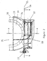
- FIG. 2 there is shown a fragmentary view of a container 30 which has first refuse entrance 31 and second refuse entrance 32.
- panel 10 is shown in the second position, i.e. panel is over second refuse entrance 32.
- the container 30 is provided with a combined hopper entrance 29, a first refuse entrance 31 and a second refuse entrance 32.
- the second refuse entrance surrounds the first refuse entrance 32, the outer extremities of each of the refuse entrances being defined by the side walls 33 and 34 and access to both refuse entrances is via the combined hopper entrance 29.
- the side wall of the first refuse entrance 33 defines the side wall of the upper hopper and the side wall of the second refuse entrance defines the side wall of the lower hopper 34.
- a roof 35 which partly covers the refuse entrances but completely covers the container 30 is provided as well.
- the upper hopper includes an upper hopper floor 40 shown in Figure 4 and the lower hopper has a lower hopper floor 41.
- the two hoppers are separated by the side wall 33 and upper floor 40.
- the upper hopper floor 40 extends into the container 30 to form the divider 42 between the upper refuse storage compartment 48 and the lower refuse storage compartment 49.
- the upper hopper floor is provided with oscillating compactor 50 and the lower hopper floor is provided with a compactor 51, both compactors being driven by the drive shaft 52.
- the compactors 50 and 51 apart from compacting refuse directed into each of the respective hoppers, also service to push the refuse material into the respective refuse storage compartments 48 and 49.
- a panel 10 in three possible positions. In position 10a the panel is shown as closing off the second refuse entrance 32. It is noted that the panel may have a rubbery extension 43 which extends to the side wall of the respective refuse entrance to prevent unwanted refuse from entering the respective refuse entrance when it is closed by the panel.
- the panel is shown as closing off the first refuse entrance 31.
- the panel may in fact allow entry of refuse into the respective refuse entrance even though it is closed off by a panel if the valve described with reference to Figure 1 by the moveable sliding door is open.
- the panel is also shown in the intermediate position 10b where it is vertically directed. In this position both the first and second refuse entrances are left open.
- This configuration may be suitable for situations where the rubbish bins used to load rubbish into the refuse collection vehicle do not have a lid which could otherwise interfere with the vertically directed panel 10b.
- the refuse collection vehicle or bin concerned may have means to move a lid out of registry or other contact with the panel 10b. This may even involve having a split lid which has a central portion allowing the panel 10b to protrude through what would otherwise be the lid portion.
- Section B-B of Figure 2 when translated to Figure 3 shows the panel 10 in Figure 3 in the configuration 10b (i.e. directed vertically) as per Figure 4 rather than directed horizontally in the configuration 10a as is shown in Figure 2.
- the refuse collection vehicle includes a bin lifter 55 which may be provided at the side of the refuse collection vehicle. This bin lifter is arranged to pick up a bin and dump the contents into the region bounded by the first and second refuse entrances 31 and 32.
- the bin may have a divider in line with the dividing line corresponding to the vertical position 10b of the panel, in order that sorted refuse contained in both sides of the bin may be initially directed to the respective refuse entrances.
- the valve of the panel 10 when the valve of the panel 10 is open and refuse from a divided bin is directed by the bin lifter to the refuse collection vehicle, refuse provided in either side of the bin is directed to the first and second refuse entrances in accordance with their alignment to the compartments in the bin. However, if it is desired that all of the refuse in the bin should be directed to one or other of the compartments in the refuse storage compartment, the panel 10 may be moved to close off either the first or second refuse entrance with the valve in a closed configuration.
- the refuse collection vehicle may include an automatic cycle which lifts the panel to something approximating the position shown in Figure 4 at location 10b to dump the "hung up refuse" into the open refuse entrance. It may then return to its original position closing off the respective refuse entrance ready for the next bin dumping cycle.
- the lower rod 14 about which the panel pivots may be directed at a slight angle to the horizontal in order to assist refuse to fall into the opening created for entry into the respective refuse entrance when the valve constituted by the sliding door 16 is open.
- FIG. 5A there is shown a single bin 100 ie. a bin which is not compartmentalised, inverted above the combined hopper entrance 29 giving access to the two refuse entrances 31 and 32.
- the panel 10 is shaded to indicate that the sliding door 16 or valve is closed, thus blocking entry of all refuse into the lower hopper 39.
- all refuse from the bin 100 ultimately falls along the direction of the arrow 108 into the upper hopper 38 when the panel is located in the position illustrated in the drawing.
- the panel may be moved to a position near vertical to ensure that any refuse hung up on the panel ultimately drops into the upper hopper.
- the panel 10 is again shown with the sliding door 16 closed, but in this configuration the panel blocks entry to the upper hopper 38 and all refuse flows to the lower hopper as shown by the arrow 105.
- valve is open and refuse from the left side of the split bin 101 shown by the arrow 106 falls through the open valve into the lower hopper to be compacted by compactor 51 and pushed into the lower refuse storage compartment 49.
- the refuse from the right side of the split bin as shown by arrow 107 falls into the upper hopper to be compacted by the compactor 50 and pushed into the upper refuse storage compartment.
- the refuse vehicle of the invention is very adaptable as it can be used to pick up refuse from single bins or split bins while still being able to keep segregated refuse from the split bins separated. Furthermore it can accommodate single bins having different types of refuse by diverting a particular refuse type to one or the other of the storage compartments. It can even be used for situations where there is no refuse segregation as the refuse can be simultaneously directed to both storage compartments, or alternately to one or the other storage compartment depending on how full they are. For example, if one storage compartment is full while the other still has further capacity, sensing means which may be associated with the paddles or the storage compartments themselves may act to divert further refuse to the unfilled compartment.
Landscapes
- Engineering & Computer Science (AREA)
- Mechanical Engineering (AREA)
- Refuse-Collection Vehicles (AREA)
- Processing Of Solid Wastes (AREA)
- Refuse Collection And Transfer (AREA)
- Soil Working Implements (AREA)
Claims (11)
- Camion à ordures comprenant :caractérisé en ce que le panneau (10) est prévu avec des moyens de clapet comprenant une porte (16) dans le panneau (10), les moyens de clapet pouvant fonctionner pour ouvrir et fermer l'entrée à travers laquelle au moins l'une des entrées d'ordures (31, 32) lorsque le panneau (10) est en alignement avec l'entrée d'ordures (31, 32) respective.un conteneur (30) ;des premier (48) et second (49) compartiments de stockage d'ordures situés dans le conteneur (30) ;des première (31) et seconde (32) entrées d'ordures pour faciliter l'entrée des ordures dans les premier (48) et second (49) compartiments de stockage d'ordures respectifs ;un panneau (10) mobile de manière alternée en alignement avec les première (31) et seconde (32) entrées d'ordures pour recouvrir l'entrée respective, et comprenant en outre des moyens d'entraínement (22) adaptés pour faire pivoter le panneau (10) autour d'un bord du panneau (10) pour le déplacer en alignement avec les entrées (31, 32) d'ordures respectives,
- Camion à ordures selon la revendication 1, dans lequel la porte (16) peut être coulissée de sorte qu'au moment où le clapet est ouvert, la porte (16) est située au moins partiellement dans une partie de manchon (17) du panneau (10).
- Camion à ordures selon la revendication 1 ou 2, dans lequel le panneau (10) comprend un vérin hydraulique (18) pour déplacer la porte (16).
- Camion à ordures selon l'une quelconque des revendications précédentes, dans lequel les première (31) et seconde (32) entrées d'ordures sont agencées de sorte que la première entrée d'ordures (31) se trouve dans la seconde entrée d'ordures (32), les entrées d'ordures (31, 32) proposant respectivement l'accès à des trémies interne et externe.
- Camion à ordures selon la revendication 4, dans lequel les trémies interne et externe sont chacune équipées avec un compacteur (50, 51) pour compacter les ordures et les pousser dans le compartiment à ordures (48, 49) respectif.
- Camion à ordures selon la revendication 5, dans lequel les compacteurs (50, 51) pour les trémies interne et externe comprennent chacune une palette qui est raccordée à un arbre d'entraínement commun (52).
- Camion à ordures selon l'une quelconque des revendications précédentes, comprenant un dispositif de levage de benne (55) pour ramasser une benne à ordures et la renverser au dessus des première et seconde entrées d'ordures (31, 32).
- Camion à ordures selon l'une quelconque des revendications précédentes, dans lequel le panneau (10) est adapté pour recouvrir au moins partiellement les entrées d'ordures (31, 32) lorsqu'il est aligné avec elles, et pour être légèrement incliné à l'horizontale lorsqu'il est en alignement.
- Camion à ordures selon la revendication 8, dans lequel le panneau (10) est adapté pour pivoter autour d'un axe incliné à l'horizontale.
- Camion à ordures selon l'une quelconque des revendications précédentes, dans lequel le panneau (10) comprend un châssis (11) recouvert avec des feuilles de chaque côté, formant un manchon (17) et la porte (16) pouvant coulisser dans et hors du manchon (17) pour ouvrir et fermer le clapet qui est formé ainsi.
- Camion à ordures selon l'une quelconque des revendications précédentes, dans lequel les première (31) et seconde (32) entrées d'ordures sont situées entre la cabine du camion et les premier (48) et second (49) compartiments de stockage.
Applications Claiming Priority (3)
| Application Number | Priority Date | Filing Date | Title |
|---|---|---|---|
| AUPP1095A AUPP109597A0 (en) | 1997-12-23 | 1997-12-23 | Divided refuse vehicle |
| AUPP109597 | 1997-12-23 | ||
| PCT/AU1998/001071 WO1999033718A1 (fr) | 1997-12-23 | 1998-12-22 | Ameliorations portant sur des camions a ordures a compartiments |
Publications (3)
| Publication Number | Publication Date |
|---|---|
| EP1064208A1 EP1064208A1 (fr) | 2001-01-03 |
| EP1064208A4 EP1064208A4 (fr) | 2001-08-22 |
| EP1064208B1 true EP1064208B1 (fr) | 2004-08-04 |
Family
ID=3805377
Family Applications (1)
| Application Number | Title | Priority Date | Filing Date |
|---|---|---|---|
| EP98960928A Expired - Lifetime EP1064208B1 (fr) | 1997-12-23 | 1998-12-22 | Camion a ordures a compartiments |
Country Status (5)
| Country | Link |
|---|---|
| EP (1) | EP1064208B1 (fr) |
| AT (1) | ATE272552T1 (fr) |
| AU (1) | AUPP109597A0 (fr) |
| DE (1) | DE69825489T2 (fr) |
| WO (1) | WO1999033718A1 (fr) |
Families Citing this family (5)
| Publication number | Priority date | Publication date | Assignee | Title |
|---|---|---|---|---|
| ES2178534B1 (es) * | 2000-02-22 | 2004-08-16 | Mbe Sotkon, S.L. | Sistema para acceso automatico y directo a diferentes tolvas compartimntadas en vehiculos de recogida de residuos solidos urbanos. |
| EP2524881B1 (fr) * | 2011-05-19 | 2021-02-24 | HS Fahrzeugbau GmbH | Véhicule pour déchets avec trémie de chargement et un dispositif de commande destiné au blocage d'une zone partielle |
| GB201604060D0 (en) * | 2016-03-09 | 2016-04-20 | Romaquip Ltd | A refuse collection vehicle and method of collecting and discharging refuse from a refuse collection vehicle |
| CN106429134B (zh) * | 2016-11-25 | 2023-02-28 | 泸州新兴环卫设备制造有限公司 | 一种水平压缩垃圾中转站 |
| CN108001918B (zh) * | 2017-12-28 | 2023-10-20 | 山东五征集团有限公司 | 可分类装卸式垃圾车车箱 |
Family Cites Families (7)
| Publication number | Priority date | Publication date | Assignee | Title |
|---|---|---|---|---|
| DE3829076C1 (fr) * | 1988-08-27 | 1989-12-28 | E.S.D. Entsorgungs-Systeme Fuer Deutschland Gmbh & Co, 8900 Augsburg, De | |
| NZ249049A (en) * | 1992-02-10 | 1996-08-27 | Firebelt Pty Ltd | Side loading refuse collection vehicle for the use with wheeled bins |
| AU715010B2 (en) * | 1995-03-14 | 2000-01-13 | Patents4Us Pty Ltd | A container |
| WO1997006031A1 (fr) * | 1995-08-04 | 1997-02-20 | Kann Manufacturing Corporation | Mecanisme de formation de trajets de deversement dans une benne a plusieurs compartiments d'un vehicule de collecte d'ordures |
| US5823728A (en) * | 1996-02-12 | 1998-10-20 | Toccoa Metal Technologies, Inc. | Segmented residential front loading refuse collection vehicle |
| DE29615226U1 (de) * | 1996-08-31 | 1996-10-17 | Behling, Hans-Jürgen, 30459 Hannover | Abfallsammelfahrzeug |
| AU5279498A (en) * | 1997-01-30 | 1998-08-06 | Superior Pak Intellectual Property Pty Ltd | Divider mechanism for waste hopper |
-
1997
- 1997-12-23 AU AUPP1095A patent/AUPP109597A0/en not_active Abandoned
-
1998
- 1998-12-22 DE DE69825489T patent/DE69825489T2/de not_active Expired - Lifetime
- 1998-12-22 AT AT98960928T patent/ATE272552T1/de not_active IP Right Cessation
- 1998-12-22 EP EP98960928A patent/EP1064208B1/fr not_active Expired - Lifetime
- 1998-12-22 WO PCT/AU1998/001071 patent/WO1999033718A1/fr not_active Ceased
Also Published As
| Publication number | Publication date |
|---|---|
| AUPP109597A0 (en) | 1998-01-22 |
| DE69825489D1 (de) | 2004-09-09 |
| ATE272552T1 (de) | 2004-08-15 |
| DE69825489T2 (de) | 2005-08-18 |
| WO1999033718A1 (fr) | 1999-07-08 |
| EP1064208A1 (fr) | 2001-01-03 |
| EP1064208A4 (fr) | 2001-08-22 |
Similar Documents
| Publication | Publication Date | Title |
|---|---|---|
| US5919026A (en) | Carry can discharge floor | |
| DE3537546C2 (fr) | ||
| US5074737A (en) | Trash collection vehicle | |
| US6655894B2 (en) | Refuse collection vehicle with dual storage chute system | |
| US4979866A (en) | Waste collecting vehicles and plastic waste compactors therefor | |
| US5584642A (en) | Refuse collection vehicle and apparatus associated therewith | |
| US6027300A (en) | Side-loading refuse vehicle | |
| US6120079A (en) | Garbage collection and transport system | |
| KR101871260B1 (ko) | 다목적 쓰레기 수거차량 | |
| EP1064208A1 (fr) | Ameliorations portant sur des camions a ordures a compartiments | |
| US5823728A (en) | Segmented residential front loading refuse collection vehicle | |
| AU2001100664A4 (en) | Improvements relating to divided refuse vehicles | |
| AU715010B2 (en) | A container | |
| AU9740301A (en) | Improvements relating to divided refuse vehicles | |
| US5443355A (en) | Trash collection vehicle | |
| EP0721421B1 (fr) | Camion de collecte | |
| US6821077B2 (en) | Waste and recyclable materials compaction and handling apparatus | |
| AU676371B2 (en) | Waste collection vehicle | |
| EP3351490B1 (fr) | Système de chargement pour véhicule de collecte de déchets | |
| JP3169674B2 (ja) | 塵芥収集車 | |
| JPH0644882Y2 (ja) | 塵芥収集車 | |
| CA2344801A1 (fr) | Contenant pour la manutention de dechets ou de materiaux recyclables | |
| AU683691B2 (en) | Improvements relating to refuse truck split bin loading systems | |
| AU683691C (en) | Improvements relating to refuse truck split bin loading systems | |
| AU651031B2 (en) | A side-loading refuse vehicle |
Legal Events
| Date | Code | Title | Description |
|---|---|---|---|
| PUAI | Public reference made under article 153(3) epc to a published international application that has entered the european phase |
Free format text: ORIGINAL CODE: 0009012 |
|
| 17P | Request for examination filed |
Effective date: 20000621 |
|
| AK | Designated contracting states |
Kind code of ref document: A1 Designated state(s): AT BE CH CY DE DK ES FI FR GB GR IE IT LI LU MC NL PT SE |
|
| A4 | Supplementary search report drawn up and despatched |
Effective date: 20010705 |
|
| AK | Designated contracting states |
Kind code of ref document: A4 Designated state(s): AT BE CH CY DE DK ES FI FR GB GR IE IT LI LU MC NL PT SE |
|
| 17Q | First examination report despatched |
Effective date: 20020809 |
|
| GRAP | Despatch of communication of intention to grant a patent |
Free format text: ORIGINAL CODE: EPIDOSNIGR1 |
|
| RTI1 | Title (correction) |
Free format text: DIVIDED REFUSE COLLECTION VEHICLE |
|
| GRAS | Grant fee paid |
Free format text: ORIGINAL CODE: EPIDOSNIGR3 |
|
| GRAA | (expected) grant |
Free format text: ORIGINAL CODE: 0009210 |
|
| AK | Designated contracting states |
Kind code of ref document: B1 Designated state(s): AT BE CH CY DE DK ES FI FR GB GR IE IT LI LU MC NL PT SE |
|
| PG25 | Lapsed in a contracting state [announced via postgrant information from national office to epo] |
Ref country code: LI Free format text: LAPSE BECAUSE OF FAILURE TO SUBMIT A TRANSLATION OF THE DESCRIPTION OR TO PAY THE FEE WITHIN THE PRESCRIBED TIME-LIMIT Effective date: 20040804 Ref country code: IT Free format text: LAPSE BECAUSE OF FAILURE TO SUBMIT A TRANSLATION OF THE DESCRIPTION OR TO PAY THE FEE WITHIN THE PRESCRIBED TIME-LIMIT;WARNING: LAPSES OF ITALIAN PATENTS WITH EFFECTIVE DATE BEFORE 2007 MAY HAVE OCCURRED AT ANY TIME BEFORE 2007. THE CORRECT EFFECTIVE DATE MAY BE DIFFERENT FROM THE ONE RECORDED. Effective date: 20040804 Ref country code: FR Free format text: LAPSE BECAUSE OF FAILURE TO SUBMIT A TRANSLATION OF THE DESCRIPTION OR TO PAY THE FEE WITHIN THE PRESCRIBED TIME-LIMIT Effective date: 20040804 Ref country code: FI Free format text: LAPSE BECAUSE OF FAILURE TO SUBMIT A TRANSLATION OF THE DESCRIPTION OR TO PAY THE FEE WITHIN THE PRESCRIBED TIME-LIMIT Effective date: 20040804 Ref country code: CY Free format text: LAPSE BECAUSE OF FAILURE TO SUBMIT A TRANSLATION OF THE DESCRIPTION OR TO PAY THE FEE WITHIN THE PRESCRIBED TIME-LIMIT Effective date: 20040804 Ref country code: CH Free format text: LAPSE BECAUSE OF FAILURE TO SUBMIT A TRANSLATION OF THE DESCRIPTION OR TO PAY THE FEE WITHIN THE PRESCRIBED TIME-LIMIT Effective date: 20040804 Ref country code: AT Free format text: LAPSE BECAUSE OF FAILURE TO SUBMIT A TRANSLATION OF THE DESCRIPTION OR TO PAY THE FEE WITHIN THE PRESCRIBED TIME-LIMIT Effective date: 20040804 |
|
| REG | Reference to a national code |
Ref country code: GB Ref legal event code: FG4D |
|
| REG | Reference to a national code |
Ref country code: CH Ref legal event code: EP |
|
| REG | Reference to a national code |
Ref country code: IE Ref legal event code: FG4D |
|
| REF | Corresponds to: |
Ref document number: 69825489 Country of ref document: DE Date of ref document: 20040909 Kind code of ref document: P |
|
| PG25 | Lapsed in a contracting state [announced via postgrant information from national office to epo] |
Ref country code: SE Free format text: LAPSE BECAUSE OF FAILURE TO SUBMIT A TRANSLATION OF THE DESCRIPTION OR TO PAY THE FEE WITHIN THE PRESCRIBED TIME-LIMIT Effective date: 20041104 Ref country code: GR Free format text: LAPSE BECAUSE OF FAILURE TO SUBMIT A TRANSLATION OF THE DESCRIPTION OR TO PAY THE FEE WITHIN THE PRESCRIBED TIME-LIMIT Effective date: 20041104 Ref country code: DK Free format text: LAPSE BECAUSE OF FAILURE TO SUBMIT A TRANSLATION OF THE DESCRIPTION OR TO PAY THE FEE WITHIN THE PRESCRIBED TIME-LIMIT Effective date: 20041104 |
|
| PG25 | Lapsed in a contracting state [announced via postgrant information from national office to epo] |
Ref country code: ES Free format text: LAPSE BECAUSE OF FAILURE TO SUBMIT A TRANSLATION OF THE DESCRIPTION OR TO PAY THE FEE WITHIN THE PRESCRIBED TIME-LIMIT Effective date: 20041115 |
|
| PG25 | Lapsed in a contracting state [announced via postgrant information from national office to epo] |
Ref country code: LU Free format text: LAPSE BECAUSE OF NON-PAYMENT OF DUE FEES Effective date: 20041222 Ref country code: IE Free format text: LAPSE BECAUSE OF NON-PAYMENT OF DUE FEES Effective date: 20041222 |
|
| PG25 | Lapsed in a contracting state [announced via postgrant information from national office to epo] |
Ref country code: MC Free format text: LAPSE BECAUSE OF NON-PAYMENT OF DUE FEES Effective date: 20041231 |
|
| REG | Reference to a national code |
Ref country code: CH Ref legal event code: PL |
|
| PLBE | No opposition filed within time limit |
Free format text: ORIGINAL CODE: 0009261 |
|
| STAA | Information on the status of an ep patent application or granted ep patent |
Free format text: STATUS: NO OPPOSITION FILED WITHIN TIME LIMIT |
|
| 26N | No opposition filed |
Effective date: 20050506 |
|
| EN | Fr: translation not filed | ||
| REG | Reference to a national code |
Ref country code: IE Ref legal event code: MM4A |
|
| PG25 | Lapsed in a contracting state [announced via postgrant information from national office to epo] |
Ref country code: PT Free format text: LAPSE BECAUSE OF NON-PAYMENT OF DUE FEES Effective date: 20050104 |
|
| PGFP | Annual fee paid to national office [announced via postgrant information from national office to epo] |
Ref country code: BE Payment date: 20071219 Year of fee payment: 10 |
|
| BERE | Be: lapsed |
Owner name: *MACDONALD JOHNSTON ENGINEERING CO. PTY. LTD Effective date: 20081231 |
|
| PG25 | Lapsed in a contracting state [announced via postgrant information from national office to epo] |
Ref country code: BE Free format text: LAPSE BECAUSE OF NON-PAYMENT OF DUE FEES Effective date: 20081231 |
|
| PGFP | Annual fee paid to national office [announced via postgrant information from national office to epo] |
Ref country code: NL Payment date: 20161228 Year of fee payment: 19 Ref country code: GB Payment date: 20161003 Year of fee payment: 19 Ref country code: DE Payment date: 20161213 Year of fee payment: 19 |
|
| REG | Reference to a national code |
Ref country code: DE Ref legal event code: R119 Ref document number: 69825489 Country of ref document: DE |
|
| REG | Reference to a national code |
Ref country code: NL Ref legal event code: MM Effective date: 20180101 |
|
| GBPC | Gb: european patent ceased through non-payment of renewal fee |
Effective date: 20171222 |
|
| PG25 | Lapsed in a contracting state [announced via postgrant information from national office to epo] |
Ref country code: NL Free format text: LAPSE BECAUSE OF NON-PAYMENT OF DUE FEES Effective date: 20180101 |
|
| PG25 | Lapsed in a contracting state [announced via postgrant information from national office to epo] |
Ref country code: DE Free format text: LAPSE BECAUSE OF NON-PAYMENT OF DUE FEES Effective date: 20180703 |
|
| PG25 | Lapsed in a contracting state [announced via postgrant information from national office to epo] |
Ref country code: GB Free format text: LAPSE BECAUSE OF NON-PAYMENT OF DUE FEES Effective date: 20171222 |