EP1064457B1 - Verfahren zum bestimmen der einspritzzeit bei einer direkteinspritzenden brennkraftmaschine - Google Patents
Verfahren zum bestimmen der einspritzzeit bei einer direkteinspritzenden brennkraftmaschine Download PDFInfo
- Publication number
- EP1064457B1 EP1064457B1 EP99913110A EP99913110A EP1064457B1 EP 1064457 B1 EP1064457 B1 EP 1064457B1 EP 99913110 A EP99913110 A EP 99913110A EP 99913110 A EP99913110 A EP 99913110A EP 1064457 B1 EP1064457 B1 EP 1064457B1
- Authority
- EP
- European Patent Office
- Prior art keywords
- injection
- pressure
- fuel
- combustion engine
- internal combustion
- Prior art date
- Legal status (The legal status is an assumption and is not a legal conclusion. Google has not performed a legal analysis and makes no representation as to the accuracy of the status listed.)
- Expired - Lifetime
Links
- 238000002347 injection Methods 0.000 title claims description 73
- 239000007924 injection Substances 0.000 title claims description 73
- 238000000034 method Methods 0.000 title claims description 25
- 238000002485 combustion reaction Methods 0.000 title claims description 20
- 239000000446 fuel Substances 0.000 claims description 33
- 230000008569 process Effects 0.000 claims description 13
- 230000010355 oscillation Effects 0.000 claims description 7
- 238000013016 damping Methods 0.000 claims description 6
- 238000012937 correction Methods 0.000 claims description 4
- 238000010586 diagram Methods 0.000 claims 1
- 230000001960 triggered effect Effects 0.000 description 4
- VREFGVBLTWBCJP-UHFFFAOYSA-N alprazolam Chemical compound C12=CC(Cl)=CC=C2N2C(C)=NN=C2CN=C1C1=CC=CC=C1 VREFGVBLTWBCJP-UHFFFAOYSA-N 0.000 description 3
- 238000013459 approach Methods 0.000 description 3
- 239000002828 fuel tank Substances 0.000 description 3
- 230000006835 compression Effects 0.000 description 2
- 238000007906 compression Methods 0.000 description 2
- 238000005314 correlation function Methods 0.000 description 2
- 230000033001 locomotion Effects 0.000 description 2
- 238000005259 measurement Methods 0.000 description 2
- 230000004913 activation Effects 0.000 description 1
- 238000004364 calculation method Methods 0.000 description 1
- 230000008859 change Effects 0.000 description 1
- 230000002596 correlated effect Effects 0.000 description 1
- 230000000875 corresponding effect Effects 0.000 description 1
- 238000013461 design Methods 0.000 description 1
- 238000001514 detection method Methods 0.000 description 1
- 238000011161 development Methods 0.000 description 1
- 230000018109 developmental process Effects 0.000 description 1
- 238000010790 dilution Methods 0.000 description 1
- 239000012895 dilution Substances 0.000 description 1
- 230000006870 function Effects 0.000 description 1
- 239000002245 particle Substances 0.000 description 1
- 238000012545 processing Methods 0.000 description 1
- 230000001105 regulatory effect Effects 0.000 description 1
- 230000004044 response Effects 0.000 description 1
- 230000003068 static effect Effects 0.000 description 1
- 230000009466 transformation Effects 0.000 description 1
- 230000001052 transient effect Effects 0.000 description 1
Images


Classifications
-
- F—MECHANICAL ENGINEERING; LIGHTING; HEATING; WEAPONS; BLASTING
- F02—COMBUSTION ENGINES; HOT-GAS OR COMBUSTION-PRODUCT ENGINE PLANTS
- F02D—CONTROLLING COMBUSTION ENGINES
- F02D41/00—Electrical control of supply of combustible mixture or its constituents
- F02D41/30—Controlling fuel injection
- F02D41/38—Controlling fuel injection of the high pressure type
- F02D41/3809—Common rail control systems
- F02D41/3836—Controlling the fuel pressure
-
- F—MECHANICAL ENGINEERING; LIGHTING; HEATING; WEAPONS; BLASTING
- F02—COMBUSTION ENGINES; HOT-GAS OR COMBUSTION-PRODUCT ENGINE PLANTS
- F02D—CONTROLLING COMBUSTION ENGINES
- F02D41/00—Electrical control of supply of combustible mixture or its constituents
- F02D41/30—Controlling fuel injection
- F02D41/38—Controlling fuel injection of the high pressure type
- F02D41/40—Controlling fuel injection of the high pressure type with means for controlling injection timing or duration
- F02D41/402—Multiple injections
- F02D41/403—Multiple injections with pilot injections
-
- F—MECHANICAL ENGINEERING; LIGHTING; HEATING; WEAPONS; BLASTING
- F02—COMBUSTION ENGINES; HOT-GAS OR COMBUSTION-PRODUCT ENGINE PLANTS
- F02B—INTERNAL-COMBUSTION PISTON ENGINES; COMBUSTION ENGINES IN GENERAL
- F02B3/00—Engines characterised by air compression and subsequent fuel addition
- F02B3/06—Engines characterised by air compression and subsequent fuel addition with compression ignition
-
- F—MECHANICAL ENGINEERING; LIGHTING; HEATING; WEAPONS; BLASTING
- F02—COMBUSTION ENGINES; HOT-GAS OR COMBUSTION-PRODUCT ENGINE PLANTS
- F02D—CONTROLLING COMBUSTION ENGINES
- F02D41/00—Electrical control of supply of combustible mixture or its constituents
- F02D41/24—Electrical control of supply of combustible mixture or its constituents characterised by the use of digital means
- F02D41/26—Electrical control of supply of combustible mixture or its constituents characterised by the use of digital means using computer, e.g. microprocessor
- F02D41/28—Interface circuits
- F02D2041/286—Interface circuits comprising means for signal processing
- F02D2041/288—Interface circuits comprising means for signal processing for performing a transformation into the frequency domain, e.g. Fourier transformation
-
- F—MECHANICAL ENGINEERING; LIGHTING; HEATING; WEAPONS; BLASTING
- F02—COMBUSTION ENGINES; HOT-GAS OR COMBUSTION-PRODUCT ENGINE PLANTS
- F02D—CONTROLLING COMBUSTION ENGINES
- F02D41/00—Electrical control of supply of combustible mixture or its constituents
- F02D41/30—Controlling fuel injection
- F02D41/38—Controlling fuel injection of the high pressure type
- F02D2041/389—Controlling fuel injection of the high pressure type for injecting directly into the cylinder
-
- F—MECHANICAL ENGINEERING; LIGHTING; HEATING; WEAPONS; BLASTING
- F02—COMBUSTION ENGINES; HOT-GAS OR COMBUSTION-PRODUCT ENGINE PLANTS
- F02D—CONTROLLING COMBUSTION ENGINES
- F02D2200/00—Input parameters for engine control
- F02D2200/02—Input parameters for engine control the parameters being related to the engine
- F02D2200/06—Fuel or fuel supply system parameters
- F02D2200/0602—Fuel pressure
-
- F—MECHANICAL ENGINEERING; LIGHTING; HEATING; WEAPONS; BLASTING
- F02—COMBUSTION ENGINES; HOT-GAS OR COMBUSTION-PRODUCT ENGINE PLANTS
- F02D—CONTROLLING COMBUSTION ENGINES
- F02D2200/00—Input parameters for engine control
- F02D2200/02—Input parameters for engine control the parameters being related to the engine
- F02D2200/06—Fuel or fuel supply system parameters
- F02D2200/0614—Actual fuel mass or fuel injection amount
-
- F—MECHANICAL ENGINEERING; LIGHTING; HEATING; WEAPONS; BLASTING
- F02—COMBUSTION ENGINES; HOT-GAS OR COMBUSTION-PRODUCT ENGINE PLANTS
- F02D—CONTROLLING COMBUSTION ENGINES
- F02D2250/00—Engine control related to specific problems or objectives
- F02D2250/04—Fuel pressure pulsation in common rails
-
- F—MECHANICAL ENGINEERING; LIGHTING; HEATING; WEAPONS; BLASTING
- F02—COMBUSTION ENGINES; HOT-GAS OR COMBUSTION-PRODUCT ENGINE PLANTS
- F02D—CONTROLLING COMBUSTION ENGINES
- F02D2250/00—Engine control related to specific problems or objectives
- F02D2250/31—Control of the fuel pressure
-
- F—MECHANICAL ENGINEERING; LIGHTING; HEATING; WEAPONS; BLASTING
- F02—COMBUSTION ENGINES; HOT-GAS OR COMBUSTION-PRODUCT ENGINE PLANTS
- F02D—CONTROLLING COMBUSTION ENGINES
- F02D41/00—Electrical control of supply of combustible mixture or its constituents
- F02D41/30—Controlling fuel injection
- F02D41/38—Controlling fuel injection of the high pressure type
- F02D41/40—Controlling fuel injection of the high pressure type with means for controlling injection timing or duration
- F02D41/402—Multiple injections
-
- Y—GENERAL TAGGING OF NEW TECHNOLOGICAL DEVELOPMENTS; GENERAL TAGGING OF CROSS-SECTIONAL TECHNOLOGIES SPANNING OVER SEVERAL SECTIONS OF THE IPC; TECHNICAL SUBJECTS COVERED BY FORMER USPC CROSS-REFERENCE ART COLLECTIONS [XRACs] AND DIGESTS
- Y02—TECHNOLOGIES OR APPLICATIONS FOR MITIGATION OR ADAPTATION AGAINST CLIMATE CHANGE
- Y02T—CLIMATE CHANGE MITIGATION TECHNOLOGIES RELATED TO TRANSPORTATION
- Y02T10/00—Road transport of goods or passengers
- Y02T10/10—Internal combustion engine [ICE] based vehicles
- Y02T10/40—Engine management systems
Definitions
- the invention relates to a method for determining the injection time in a direct injection internal combustion engine according to the preamble of claim 1.
- Diesel direct injection is one Control.
- the combustion process with regard to exhaust gas emissions and to optimize the combustion noise, it is known, the injection process in one or more pilot injections and in one or more main injections divide.
- the required amount of injection into the cylinders required control time of the injectors is determined by a map determined.
- An important input variable for the map is the current pressure in the supply line or in Pressure accumulator, often as a common rail or simply as a rail referred to, since this is measured.
- the pressure in the supply is assumed to be constant in known systems. That the control time becomes the same pressure of the injectors for the pre and the main injection determined.
- the pressure between two consecutive injections e.g. between pre and main injection but can only be regarded as constant in rough approximation, as measurements prove.
- the invention has for its object a method for Determining the injection time in an internal combustion engine Specify initially mentioned type, so that in a division of the injection process into several injections The amount of fuel corresponds as closely as possible to the target value.
- the pressure fluctuations that occur during two consecutive Injections (e.g. pre and main injection) within the same working cycle of a cylinder in the supply line to the injector are taken into account with a correction term and with the corrected pressure the activation time of the Injectors determined so that the desired amount of fuel is injected.
- the correction term is determined using a Least squares estimator, which depends on the geometric data of the system, especially the length of the Supply from the rail to the injector and the physical Boundary conditions, e.g. the fuel temperature the injection pressure at the injector nozzle.
- Figure 1 shows schematically the structure of a fuel injection system for a direct injection internal combustion engine, as they are called common rail system above all used in vehicles with a diesel internal combustion engine becomes.
- the control unit 19 is preferably in one integrated electronic control unit 28 of the internal combustion engine, all of which are necessary to operate the internal combustion engine Controls and / or regulates processes.
- the control unit 28 of the internal combustion engine by means of a corresponding Sensor input signals ES supplied.
- the individual actuators and components are output signals AS controlled that to operate the internal combustion engine are necessary.
- Pressure control valve 16 controls and / or regulates one Fuel line 25 excess fuel that is not used Maintaining a desired one in the high pressure accumulator 17 Pressure is required in the fuel tank 10, wherein the holding pressure of the pressure control valve 16 from the control unit 19 is set via a control line 24.
- Pressure control in the high-pressure accumulator 17 is also a pressure sensor 23 provided. This pressure sensor 23 is used for detection of the one currently prevailing in the high-pressure accumulator 17 Pressure p, on the basis of which the control unit 19 accordingly the desired operating conditions of the internal combustion engine performs the pressure control via the pressure control valve 16.
- Fuel pressures from 0 to 1500 generate bar are available via fuel injection lines 27 on injectors or injection valves 18 (only one shown) in the combustion chambers of the internal combustion engine (not shown) are arranged. These injectors 18 generally have an injector which are closed with a spring-loaded needle is. The injection process is done by the control unit 19 triggered via control lines 26 with the injection valves 18 is connected. The one in the injectors 18 leakage current continues to occur via fuel lines 21 returned to the fuel tank 10.
- FIG. 2 shows the time course of the control signal U shown for an injector.
- the injector controlled to trigger a pre-injection.
- To a time interval at a given speed in this example corresponds to 60 ° crank angle KW, takes place at Time t2 the main injection.
- FIG. 3 The result of such a control of the injector pressure course over time is shown in FIG. 3.
- the Opening the injector nozzle triggers a pressure fluctuation, that at the time of the start of the main injection has not subsided.
- the starting pressure at the beginning of the main injection is different to the pressure at the start of the pre-injection.
- the starting pressure for the main injection can be higher or be lower and also changes in the form of a muted Vibration constantly its value.
- the short-time FFT is used for transient signals, analyze the frequency response over time. This will the measured data set in sections where the signal can be regarded as stationary, divided and these then individually transformed into the frequency domain using an FFT.
- Short-time FFT cannot start the oscillation be determined because the frequency resolution is too low.
- a One possibility is to use the cross correlation function. A vibration limited in time to a period the frequency sought is correlated with the measurement data set. The resulting relative extremum corresponds then the start of the vibration.
- the frequency f is derived from the frequency analysis using the FFT received and the start time of the vibration with the Cross correlation function obtained.
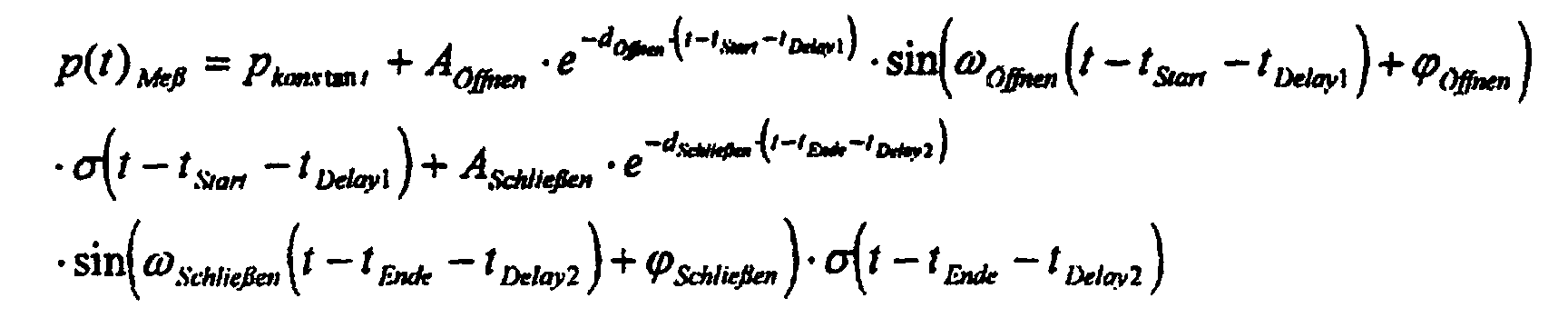
- the amplitude A, the Attenuation d and phase ⁇ are used for the signal model, namely with the least squares estimator described later certainly.
- p (t) measuring p cons tan t + p ( t ) To open + p ( t ) Conclude . wherein p cons tan t to the pressure sensor 23 is determined (Fig. 1).
- the least squares estimator is a linear estimator, i.e. the frequencies of the vibrations must be from a time-frequency analysis be won.
- Attenuation d can be corrected using a constant during design or estimated using a power series approach.
- e -dt 1- dt 1! + ( dt ) 2 2! - ( dt ) 3 3! + ...
- the least squares estimator provides phase and damping.
- the estimator is set up here as an example for a frequency for a damped oscillation that occurs.
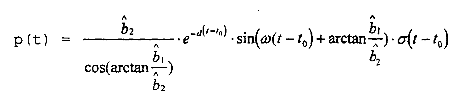
- This estimated pressure curve p (t) is shown graphically in FIG. 4b.
- the pressure curve actually occurring in the feed line (fuel injection line 27 in FIG. 1) to the injector is shown in FIG. 4a.
- the absolute error is plotted in FIG. 4c as the difference between the measured pressure curve (FIG. 4a) and the estimated pressure curve (FIG. 4b).
- the pressure can be determined using the specified Procedures can be estimated. Since the time of Start of the subsequent injection process (e.g. main injection) can be freely chosen and is known, the pressure value present at the time of the injection time calculation considered for this injection process become. This can be done, for example, in that Input variable for a in a memory 29 of the control unit 19 stored map KF, in which depending on the current Value for the rail pressure and the required fuel injection quantity Injection times are stored, not the measured one Pressure in the rail, but one around the estimated pressure value corrected pressure value is used at the start of injection. This enables the required amount of fuel to be measured with high accuracy be measured.
Landscapes
- Engineering & Computer Science (AREA)
- Chemical & Material Sciences (AREA)
- Combustion & Propulsion (AREA)
- Mechanical Engineering (AREA)
- General Engineering & Computer Science (AREA)
- Electrical Control Of Air Or Fuel Supplied To Internal-Combustion Engine (AREA)
- Combined Controls Of Internal Combustion Engines (AREA)
- Fuel-Injection Apparatus (AREA)
Description
- Figur 1
- eine schematische Darstellung eines Einspritzsystems für eine direkteinspritzende Brennkraftmaschine,
- Figur 2
- den Verlauf der Ansteuerspannung für den Injektor,
- Figur 3
- den Druckverlauf in der Zuleitung bei einer Vor-und einer Haupteinspritzung,
- Figur 4
- einen Vergleich zwischen gemessenem Druckverlauf, geschätztem Druckverlauf und den daraus berechneten Fehler des Schätzers

- A
- Amplitude
- d
- Dämpfungsfaktor
- t0
- Startzeitpunkt der Schwingung
- f
- Frequenz
- ϕ
- Phase
- σ(t - t 0)
- Sprungfunktion zum Zeitpunkt t0=0

- Aöffnen
- Amplitude der Öffnungswelle
- dÖffnen
- Dämpfung der Öffnungswelle
- ϕÖffnen
- Phase der Öffnungswelle
- ωÖffnen
- Frequenz der Öffnungswelle
- tStart
- Start der Ansteuerung
- tDelay1
- Verzugszeit bis zum öffnen der Nadel
- t0
- = tDelay1 - tStart

- ASchließen
- Amplitude der Schließwelle
- dSchließen
- Dämpfung der Schließwelle
- ϕSchließen n
- Phase der Schließwelle
- ωSchließen
- Frequenz der Schließwelle
- tEnde
- Ende der Ansteuerung
- tDelay2
- Verzugszeit bis zum Schließen der Nadel




Claims (8)
- Verfahren zum Bestimmen der Einspritzzeit bei einer direkteinspritzenden Brennkraftmaschine mit einem Kraftstoff enthaltenden Hochdruckspeicher (17), der mit einem Injektor (18) in Verbindung steht, so daß Kraftstoff abhängig von mindestens dem Druck im Hochdruckspeicher (17) und einer geforderten Kraftstoffmenge gesteuert in den Zylinder der Brennkraftmaschine eingespritzt werden kann, wobeieine berechnete und einem Zylinder der Brennkraftmaschine zuzuführende Gesamtmenge an Kraftstoff auf mindestens zwei Einspritzvorgänge pro Zylinderhub aufgeteilt ist unddie zwischen zwei einzelnen Einspritzvorgängen (n, n+1) auftretenden Druckschwankungen im Injektor (18) und in der Leitung (27) zwischen Hochdruckspeicher (17) und Injektor (18) bei der Bestimmung der Einspritzzeit für den nächsten Einspritzvorgang (n+1) berücksichtigt wird.
- Verfahren nach Anspruch 1, dadurch gekennzeichnet, daß die Gesamtmenge an Kraftstoff mittels einer Voreinspritzung (n) und einer Haupteinspritzung (n+1) zugemessen wird und die durch die Voreinspritzung ausgelösten Druckschwankungen bei der Bestimmung der Einspritzzeit für die Haupteinspritzung berücksichtigt wird.
- Verfahren nach Anspruch 1, dadurch gekennzeichnet, daß die Gesamtmenge an Kraftstoff mittels mehrerer Voreinspritzungen (n, n+1, n+i) und einer Haupteinspritzung (n+i+1) zugemessen wird und die durch die jeweiligen Voreinspritzungen ausgelösten Druckschwankungen bei der Bestimmung der Einspritzzeit für die jeweils darauffolgende Voreinspritzung bzw. der folgenden Haupteinspritzung berücksichtigt wird.
- Verfahren nach einem der Ansprüche 1-3, dadurch gekennzeichnet, daß aus den zwischen den einzelnen Einspritzvorgängen (n,n+1) auftretenden Druckschwankungen jeweils ein Korrekturterm ermittelt wird, mit dem der Druck im Hochdruckspeicher (17) korrigiert wird und mit dem korrigierten Druckwert die Einspritzzeit ermittelt wird.
- Verfahren nach Anspruch 4, dadurch gekennzeichnet, daß der korrigierte Druckwert Eingangsgröße eines Kennfeldes (KF) ist, in dem abhängig von der geforderten Kraftstoffmenge die Einspritzzeiten abgelegt sind.
- Verfahren nach Anspruch 1, dadurch gekennzeichnet, daß der Korrekturterm mit Hilfe eines Least-Square-Schätzers bestimmt wird, der in Abhängigkeit der geometrischen Daten des Einspritzsystems und der physikalischen Randbedingungen den Einspritzdruck an der Düse des Injektors (17) auf der Basis der Gleichung einer gedämpften Schwingung für die Druckschwankungen ermittelt.
- Verfahren nach Anspruch 6, dadurch gekennzeichnet, daß für die Schätzgleichung für die Druckschwankungen giltmit

- A
- Amplitude der Schwingung
- d
- Dämpfungsfaktor
- t0
- Startzeitpunkt der Schwingung
- f
- Frequenz
- ϕ
- Phase
- σ(t - t 0)
- Sprungfunktion zum Zeitpunkt t=0
- Verfahren nach Anspruch 7, dadurch gekennzeichnet, daß für den geschätzten Druckverlauf folgende Gleichung gilt:
Applications Claiming Priority (3)
| Application Number | Priority Date | Filing Date | Title |
|---|---|---|---|
| DE19811359 | 1998-03-16 | ||
| DE19811359 | 1998-03-16 | ||
| PCT/DE1999/000652 WO1999047802A1 (de) | 1998-03-16 | 1999-03-10 | Verfahren zum bestimmen der einspritzzeit bei einer direkteinspritzenden brennkraftmaschine |
Publications (2)
| Publication Number | Publication Date |
|---|---|
| EP1064457A1 EP1064457A1 (de) | 2001-01-03 |
| EP1064457B1 true EP1064457B1 (de) | 2002-06-12 |
Family
ID=7861064
Family Applications (1)
| Application Number | Title | Priority Date | Filing Date |
|---|---|---|---|
| EP99913110A Expired - Lifetime EP1064457B1 (de) | 1998-03-16 | 1999-03-10 | Verfahren zum bestimmen der einspritzzeit bei einer direkteinspritzenden brennkraftmaschine |
Country Status (4)
| Country | Link |
|---|---|
| US (1) | US6311669B1 (de) |
| EP (1) | EP1064457B1 (de) |
| DE (1) | DE59901733D1 (de) |
| WO (1) | WO1999047802A1 (de) |
Cited By (4)
| Publication number | Priority date | Publication date | Assignee | Title |
|---|---|---|---|---|
| DE10316811A1 (de) * | 2003-04-11 | 2004-11-04 | Siemens Ag | Verfahren zur Bestimmung der Einspritzzeitdauer bei einer Brennkraftmaschine mit einem Kennfeldwert und einem Korrekturwert und Verfahren zur Ermittlung des Korrekturwerts |
| DE102006033459B3 (de) * | 2006-07-19 | 2007-10-31 | Siemens Ag | Verfahren und Vorrichtung zum Betreiben einer Brennkraftmaschine |
| DE102006042098B3 (de) * | 2006-09-07 | 2008-05-21 | Siemens Ag | Verfahren zur Ermittlung einer Korrektur einer Teileinspritzmenge einer Brennkraftmaschine |
| DE202015005278U1 (de) * | 2015-07-24 | 2016-10-31 | GM Global Technology Operations LLC (n. d. Ges. d. Staates Delaware) | Computerlesbarer Datenträger und Vorrichtung zur Steuerung eines Kraftstoffinjektors |
Families Citing this family (38)
| Publication number | Priority date | Publication date | Assignee | Title |
|---|---|---|---|---|
| FR2799544B1 (fr) * | 1999-10-08 | 2002-01-04 | Siemens Automotive Sa | Procede de mesure de la pression de carburant regnant dans un injecteur electromagnetique de ce carburant dans un des cylindres d'un moteur a combustion interne a injection directe |
| DE19948971A1 (de) * | 1999-10-12 | 2001-04-19 | Bosch Gmbh Robert | Verfahren und Vorrichtung zur Steuerung einer Brennkraftmaschine |
| DE10018050C2 (de) * | 2000-04-12 | 2002-06-13 | Bosch Gmbh Robert | Verfahren zum Betreiben einer Brennkraftmaschine |
| FR2833654B1 (fr) * | 2001-12-17 | 2004-02-20 | Renault | Procede de commande d'injecteur |
| US6694953B2 (en) * | 2002-01-02 | 2004-02-24 | Caterpillar Inc | Utilization of a rail pressure predictor model in controlling a common rail fuel injection system |
| JP3966281B2 (ja) * | 2002-02-18 | 2007-08-29 | トヨタ自動車株式会社 | 内燃機関の燃料噴射制御装置及び高圧燃料の噴射供給方法 |
| JP4118652B2 (ja) | 2002-02-20 | 2008-07-16 | 株式会社デンソー | 蓄圧式燃料噴射装置 |
| JP3855846B2 (ja) * | 2002-05-21 | 2006-12-13 | トヨタ自動車株式会社 | 内燃機関の燃料噴射制御装置 |
| JP2004027910A (ja) * | 2002-06-24 | 2004-01-29 | Toyota Motor Corp | 燃料噴射制御装置 |
| FR2841940B1 (fr) * | 2002-07-08 | 2004-09-10 | Renault Sa | Procede de commande d'injecteur d'un moteur a allumage par compression a rampe commune |
| EP1424480A1 (de) * | 2002-11-28 | 2004-06-02 | STMicroelectronics S.r.l. | Virtueller Drucksensor für Common-Rail-Kraftstoffeinspritzsystem |
| DE10302806B4 (de) * | 2003-01-24 | 2004-12-09 | Siemens Ag | Verfahren zur Berechnung von Druckschwankungen in einem Kraftstoffversorgungssystem einer mit Kraftstoff-Direkteinspritzung arbeitenden Brennkraftmaschine und zur Steuerung derer Einspritzventile |
| DE10305525B4 (de) * | 2003-02-11 | 2014-04-24 | Robert Bosch Gmbh | Verfahren und Vorrichtung zur Adaption der Druckwellenkorrektur in einem Hochdruck-Einspritzsystem eines Kraftfahrzeuges im Fahrbetrieb |
| DE10313419A1 (de) * | 2003-03-25 | 2004-11-04 | Robert Bosch Gmbh | Hubgesteuerter Common-Rail-Injektor mit Steller für Schwingungsanregung |
| DE10328789A1 (de) * | 2003-06-26 | 2005-01-27 | Robert Bosch Gmbh | Verfahren und Vorrichtung zur druckwellenkompensierenden Steuerung eines Einspritzsystems einer Brennkraftmaschine |
| JP3941761B2 (ja) * | 2003-09-01 | 2007-07-04 | トヨタ自動車株式会社 | 内燃機関の燃料噴射装置 |
| DE102004006558B3 (de) * | 2004-02-10 | 2005-09-08 | Siemens Ag | Verfahren zur Ermittlung der benötigten Aktorenergie für die verschiedenen Einspritzarten eines Aktors einer Brennkraftmaschine |
| DE102004053418B4 (de) * | 2004-03-24 | 2016-05-04 | Robert Bosch Gmbh | Verfahren und Vorrichtung zur druckwellenkompensierenden Steuerung zeitlich aufeinanderfolgender Einspritzungen in einem Einspritzsystem einer Brennkraftmaschine |
| DE102004057963A1 (de) * | 2004-12-01 | 2006-06-08 | Robert Bosch Gmbh | Verfahren und Vorrichtung zur Anregung von Druckschwankungen in einem Kraftstoffversorgungssystem einer Brennkraftmaschine |
| JP4506526B2 (ja) * | 2005-03-18 | 2010-07-21 | トヨタ自動車株式会社 | 内燃機関の制御装置 |
| JP2006307800A (ja) * | 2005-05-02 | 2006-11-09 | Nissan Motor Co Ltd | エンジンの燃料供給装置 |
| DE102005036192A1 (de) * | 2005-08-02 | 2007-02-08 | Robert Bosch Gmbh | Verfahren zur Steuerung eines Einspritzsystems einer Brennkraftmaschine |
| DE102005036190A1 (de) * | 2005-08-02 | 2007-02-08 | Robert Bosch Gmbh | Verfahren und Vorrichtung zur Steuerung eines Einspritzsystems einer Brennkraftmaschine |
| EP1860311B1 (de) * | 2006-05-23 | 2009-04-22 | Delphi Technologies, Inc. | Steuerung für eine Einspritzdüse und Verfahren für den Betrieb einer Einspritzdüse |
| JP2007332783A (ja) * | 2006-06-12 | 2007-12-27 | Nissan Motor Co Ltd | エンジンの燃料供給方法及びエンジンの燃料供給装置 |
| US7835850B2 (en) * | 2007-05-08 | 2010-11-16 | Denso Corporation | Injection characteristic detection apparatus, control system, and method for the same |
| JP4462307B2 (ja) * | 2007-08-31 | 2010-05-12 | 株式会社デンソー | 燃料噴射装置及び燃料噴射システム |
| EP2105606B1 (de) * | 2008-03-04 | 2010-11-03 | Magneti Marelli S.p.A. | Common Rail Direkteinspritzanordnung mit einem Absperrventil zur Steuerung der Förderung einer Hochdruckkraftstoffpumpe |
| KR101033323B1 (ko) * | 2008-11-27 | 2011-05-09 | 현대자동차주식회사 | 커먼레일 디젤 엔진의 연료량 제어 장치 및 방법 |
| GB2475060A (en) * | 2009-11-03 | 2011-05-11 | Gm Global Tech Operations Inc | Estimating fuel injecting pressure in an i.c. engine |
| JP5522779B2 (ja) * | 2009-12-09 | 2014-06-18 | ボッシュ株式会社 | 燃料噴射量補正における補正量制御方法及びコモンレール式燃料噴射制御装置 |
| DE102010001387A1 (de) * | 2010-01-29 | 2011-08-04 | Robert Bosch GmbH, 70469 | Verfahren und Vorrichtung zur Prüfung eines Kraftstoffinjektors |
| DE102010030545B4 (de) * | 2010-06-25 | 2016-12-08 | Continental Automotive Gmbh | Verfahren zur Regelung eines Kraftstoffeinspritzsystems einer Brennkraftmaschine |
| GB2485560A (en) * | 2010-11-18 | 2012-05-23 | Gm Global Tech Operations Inc | A method for estimating an instantaneous pressure value in a fuel line |
| WO2014091273A1 (en) * | 2012-12-14 | 2014-06-19 | Renault Trucks | Method for controlling an injection system of an internal combustion engine having a common rail, injection system and automotive vehicle |
| US10240545B2 (en) | 2015-12-21 | 2019-03-26 | Ford Global Technologies, Llc | Air charge estimation via manifold pressure sample at intake valve closing |
| DE102015226461B4 (de) * | 2015-12-22 | 2018-10-04 | Continental Automotive Gmbh | Verfahren zur Ermittlung des Einspritzbeginn-Zeitpunktes und der Einspritzmenge des Kraftstoffes im Normalbetrieb eines Verbrennungsmotors |
| CN113062811B (zh) * | 2021-03-08 | 2022-02-22 | 哈尔滨工程大学 | 一种根据喷油器入口压力信号的频谱特征对喷油过程关键时间特征识别的方法 |
Family Cites Families (10)
| Publication number | Priority date | Publication date | Assignee | Title |
|---|---|---|---|---|
| US4841936A (en) * | 1985-06-27 | 1989-06-27 | Toyota Jidosha Kabushiki Kaisha | Fuel injection control device of an internal combustion engine |
| JPS62186034A (ja) * | 1986-02-10 | 1987-08-14 | Toyota Motor Corp | 内燃機関の燃料噴射装置 |
| DE3937918A1 (de) * | 1989-11-15 | 1991-05-16 | Man Nutzfahrzeuge Ag | Einspritzvorrichtung fuer selbstzuendende brennkraftmaschine |
| US5176122A (en) * | 1990-11-30 | 1993-01-05 | Toyota Jidosha Kabushiki Kaisha | Fuel injection device for an internal combustion engine |
| US5678521A (en) * | 1993-05-06 | 1997-10-21 | Cummins Engine Company, Inc. | System and methods for electronic control of an accumulator fuel system |
| DE19700738C1 (de) * | 1997-01-11 | 1998-04-16 | Daimler Benz Ag | Verfahren zur Regelung der Einspritzmengen von Injektoren einer kraftstoffeinspritzenden Brennkraftmaschine |
| US5924403A (en) * | 1997-06-06 | 1999-07-20 | Detroit Diesel Corporation | Method for enhanced split injection in internal combustion engines |
| JP3590239B2 (ja) * | 1997-09-02 | 2004-11-17 | 株式会社日立ユニシアオートモティブ | 直噴ガソリンエンジンの燃料噴射制御装置 |
| DE19747231A1 (de) * | 1997-10-25 | 1999-04-29 | Bosch Gmbh Robert | Verfahren zur Einspritzung von Kraftstoff in die Brennräume einer luftverdichtenden, selbstzündenden Brennkraftmaschine |
| US6082331A (en) * | 1997-12-19 | 2000-07-04 | Caterpillar Inc. | Electronic control and method for consistently controlling the amount of fuel injected by a hydraulically activated, electronically controlled injector fuel system to an engine |
-
1999
- 1999-03-10 WO PCT/DE1999/000652 patent/WO1999047802A1/de not_active Ceased
- 1999-03-10 EP EP99913110A patent/EP1064457B1/de not_active Expired - Lifetime
- 1999-03-10 DE DE59901733T patent/DE59901733D1/de not_active Expired - Lifetime
-
2000
- 2000-09-18 US US09/663,587 patent/US6311669B1/en not_active Expired - Lifetime
Cited By (4)
| Publication number | Priority date | Publication date | Assignee | Title |
|---|---|---|---|---|
| DE10316811A1 (de) * | 2003-04-11 | 2004-11-04 | Siemens Ag | Verfahren zur Bestimmung der Einspritzzeitdauer bei einer Brennkraftmaschine mit einem Kennfeldwert und einem Korrekturwert und Verfahren zur Ermittlung des Korrekturwerts |
| DE102006033459B3 (de) * | 2006-07-19 | 2007-10-31 | Siemens Ag | Verfahren und Vorrichtung zum Betreiben einer Brennkraftmaschine |
| DE102006042098B3 (de) * | 2006-09-07 | 2008-05-21 | Siemens Ag | Verfahren zur Ermittlung einer Korrektur einer Teileinspritzmenge einer Brennkraftmaschine |
| DE202015005278U1 (de) * | 2015-07-24 | 2016-10-31 | GM Global Technology Operations LLC (n. d. Ges. d. Staates Delaware) | Computerlesbarer Datenträger und Vorrichtung zur Steuerung eines Kraftstoffinjektors |
Also Published As
| Publication number | Publication date |
|---|---|
| EP1064457A1 (de) | 2001-01-03 |
| WO1999047802A1 (de) | 1999-09-23 |
| US6311669B1 (en) | 2001-11-06 |
| DE59901733D1 (de) | 2002-07-18 |
Similar Documents
| Publication | Publication Date | Title |
|---|---|---|
| EP1064457A1 (de) | Verfahren zum bestimmen der einspritzzeit bei einer direkteinspritzenden brennkraftmaschine | |
| DE102012102559B4 (de) | Vorrichtung zur Einschätzung eines Kraftstoffzustandes | |
| EP1613853B1 (de) | Verfahren zur bestimmung der einspritzzeitdauer bei einer brennkraftmaschine mit einem kennfeldwert und einem korrekturwert und verfahren zur ermittlung des korrekturwerts | |
| DE102012102336B4 (de) | Vorrichtung zum Abschätzen eines Kraftstoffeinspritzzustands | |
| EP1561029A1 (de) | Verfahren und vorrichtung zur messung der einspritzrate eines einspritzventils f r fl ssigkeiten | |
| DE102011055779A1 (de) | Kraftstoffeinspritzcharakteristiken-Lernvorrichtung | |
| DE102011052138A1 (de) | Steuervorrichtung für Druckreduzierventile | |
| EP1884646A2 (de) | Verfahren zur Steuerung einer Brennkraftmaschine | |
| DE102011050899B4 (de) | Signalverlaufserfassungsvorrichtung für einen Kraftstoffdruck | |
| DE10302806B4 (de) | Verfahren zur Berechnung von Druckschwankungen in einem Kraftstoffversorgungssystem einer mit Kraftstoff-Direkteinspritzung arbeitenden Brennkraftmaschine und zur Steuerung derer Einspritzventile | |
| DE10029349A1 (de) | Kraftstoffeinspritz-Steueranordnung für einen Motor mit Zylindereinspritzung | |
| EP1843028B1 (de) | Verfahren zur Leckageprüfung eines ein Magnetventil aufweisenden Kraftstoffinjektors | |
| DE102007052451A1 (de) | Verfahren zum Bestimmen der aktuellen Dauerleckagemenge einer Common-Rail-Einspritzanlage und Einspritzanlage für eine Brennkraftmaschine | |
| DE102017212762A1 (de) | Verfahren zum Betreiben eines Verbrennungsmotors und elektronisches Steuergerät für einen Verbrennungsmotor | |
| DE102015113518B4 (de) | Kraftstoffdichte-Erfassungsvorrichtung | |
| DE102013224706A1 (de) | Verfahren zur Berechnung des Einspritzratenverlaufs | |
| WO2008028849A1 (de) | Verfahren und vorrichtung zur korrektur des einspritzzeitdauers bei einer brennkraftmaschine | |
| DE102008002216A1 (de) | Verfahren zum Betreiben eines Einspritzsystems mit mindestens zwei Rails für eine Brennkraftmaschine | |
| DE102007063102A1 (de) | Verfahren zur Erfassung eines periodisch pulsierenden Betriebsparameters | |
| DE102006007365B3 (de) | Verfahren zur Steuerung und Regelung einer Brennkraftmaschine | |
| DE10305525B4 (de) | Verfahren und Vorrichtung zur Adaption der Druckwellenkorrektur in einem Hochdruck-Einspritzsystem eines Kraftfahrzeuges im Fahrbetrieb | |
| WO2008009497A1 (de) | Verfahren und vorrichtung zum betreiben einer brennkraftmaschine | |
| DE102014100338A1 (de) | Kraftstoffeinspritzvorrichtung | |
| DE112016004877T5 (de) | Verfahren und System zur Bestimmung des Druckes in einem Kraftstoffspeichertank eines Motors | |
| DE10018050A1 (de) | Verfahren zum Betreiben einer Brennkraftmaschine |
Legal Events
| Date | Code | Title | Description |
|---|---|---|---|
| PUAI | Public reference made under article 153(3) epc to a published international application that has entered the european phase |
Free format text: ORIGINAL CODE: 0009012 |
|
| 17P | Request for examination filed |
Effective date: 20000417 |
|
| AK | Designated contracting states |
Kind code of ref document: A1 Designated state(s): DE FR GB |
|
| GRAG | Despatch of communication of intention to grant |
Free format text: ORIGINAL CODE: EPIDOS AGRA |
|
| GRAG | Despatch of communication of intention to grant |
Free format text: ORIGINAL CODE: EPIDOS AGRA |
|
| GRAH | Despatch of communication of intention to grant a patent |
Free format text: ORIGINAL CODE: EPIDOS IGRA |
|
| 17Q | First examination report despatched |
Effective date: 20010717 |
|
| GRAH | Despatch of communication of intention to grant a patent |
Free format text: ORIGINAL CODE: EPIDOS IGRA |
|
| GRAA | (expected) grant |
Free format text: ORIGINAL CODE: 0009210 |
|
| AK | Designated contracting states |
Kind code of ref document: B1 Designated state(s): DE FR GB |
|
| REG | Reference to a national code |
Ref country code: GB Ref legal event code: FG4D Free format text: NOT ENGLISH |
|
| REF | Corresponds to: |
Ref document number: 59901733 Country of ref document: DE Date of ref document: 20020718 |
|
| GBT | Gb: translation of ep patent filed (gb section 77(6)(a)/1977) |
Effective date: 20020815 |
|
| ET | Fr: translation filed | ||
| PLBE | No opposition filed within time limit |
Free format text: ORIGINAL CODE: 0009261 |
|
| STAA | Information on the status of an ep patent application or granted ep patent |
Free format text: STATUS: NO OPPOSITION FILED WITHIN TIME LIMIT |
|
| 26N | No opposition filed |
Effective date: 20030313 |
|
| PGFP | Annual fee paid to national office [announced via postgrant information from national office to epo] |
Ref country code: GB Payment date: 20090325 Year of fee payment: 11 |
|
| PGFP | Annual fee paid to national office [announced via postgrant information from national office to epo] |
Ref country code: FR Payment date: 20090312 Year of fee payment: 11 |
|
| GBPC | Gb: european patent ceased through non-payment of renewal fee |
Effective date: 20100310 |
|
| REG | Reference to a national code |
Ref country code: FR Ref legal event code: ST Effective date: 20101130 |
|
| PG25 | Lapsed in a contracting state [announced via postgrant information from national office to epo] |
Ref country code: FR Free format text: LAPSE BECAUSE OF NON-PAYMENT OF DUE FEES Effective date: 20100331 |
|
| PG25 | Lapsed in a contracting state [announced via postgrant information from national office to epo] |
Ref country code: GB Free format text: LAPSE BECAUSE OF NON-PAYMENT OF DUE FEES Effective date: 20100310 |
|
| PGFP | Annual fee paid to national office [announced via postgrant information from national office to epo] |
Ref country code: DE Payment date: 20180331 Year of fee payment: 20 |
|
| REG | Reference to a national code |
Ref country code: DE Ref legal event code: R071 Ref document number: 59901733 Country of ref document: DE |