EP1064514B1 - Commande de gachette - Google Patents
Commande de gachette Download PDFInfo
- Publication number
- EP1064514B1 EP1064514B1 EP99908800A EP99908800A EP1064514B1 EP 1064514 B1 EP1064514 B1 EP 1064514B1 EP 99908800 A EP99908800 A EP 99908800A EP 99908800 A EP99908800 A EP 99908800A EP 1064514 B1 EP1064514 B1 EP 1064514B1
- Authority
- EP
- European Patent Office
- Prior art keywords
- firing pin
- slide
- spring
- housing
- cartridge
- Prior art date
- Legal status (The legal status is an assumption and is not a legal conclusion. Google has not performed a legal analysis and makes no representation as to the accuracy of the status listed.)
- Expired - Lifetime
Links
- 238000010304 firing Methods 0.000 claims abstract description 90
- 230000037452 priming Effects 0.000 claims 2
- 230000001960 triggered effect Effects 0.000 description 4
- 210000002414 leg Anatomy 0.000 description 3
- 239000000463 material Substances 0.000 description 3
- 230000035939 shock Effects 0.000 description 3
- 229910000831 Steel Inorganic materials 0.000 description 2
- 239000010959 steel Substances 0.000 description 2
- 239000006228 supernatant Substances 0.000 description 2
- 230000007704 transition Effects 0.000 description 2
- 241000287828 Gallus gallus Species 0.000 description 1
- 206010053648 Vascular occlusion Diseases 0.000 description 1
- 238000005266 casting Methods 0.000 description 1
- 239000002131 composite material Substances 0.000 description 1
- 230000006835 compression Effects 0.000 description 1
- 238000007906 compression Methods 0.000 description 1
- 238000010276 construction Methods 0.000 description 1
- 230000007423 decrease Effects 0.000 description 1
- 230000000694 effects Effects 0.000 description 1
- 238000007373 indentation Methods 0.000 description 1
- 238000009434 installation Methods 0.000 description 1
- 238000004519 manufacturing process Methods 0.000 description 1
- 230000002028 premature Effects 0.000 description 1
- 230000001105 regulatory effect Effects 0.000 description 1
- 239000007787 solid Substances 0.000 description 1
- 210000000689 upper leg Anatomy 0.000 description 1
Images



Classifications
-
- F—MECHANICAL ENGINEERING; LIGHTING; HEATING; WEAPONS; BLASTING
- F41—WEAPONS
- F41A—FUNCTIONAL FEATURES OR DETAILS COMMON TO BOTH SMALLARMS AND ORDNANCE, e.g. CANNONS; MOUNTINGS FOR SMALLARMS OR ORDNANCE
- F41A17/00—Safety arrangements, e.g. safeties
- F41A17/64—Firing-pin safeties, i.e. means for preventing movement of slidably- mounted strikers
- F41A17/66—Firing-pin safeties, i.e. means for preventing movement of slidably- mounted strikers automatically operated, i.e. operated by breech opening or closing movement
Definitions
- the invention relates to a handgun with a Lock moving into one for igniting one Cartridge fitted end position is movable, one in Closure along a trajectory movably mounted firing pin with a striker pin spring (1) loading it backwards and one Demolition device by a trigger device is triggered and is set up to ignite a Cartridge on the side facing away from this firing pin end réelle transformer and thereby the firing pin in his To spend ignition position.
- a weapon is out No. 1,363,040.
- top o. The like. go out from the horizontal position of use of the weapon when Shot, wherein the weft direction points to "front” (in the Drawing to the left).
- a cock can also be provided a hammer, the not, as a cock is pivotable about a fixed axis, but e.g. guided in a straight-line movement path and is movable under load a striker.
- a cock is pivotable about a fixed axis, but e.g. guided in a straight-line movement path and is movable under load a striker.
- the trigger means To prevent the tap from knocking off already, open the firing pin end hits and the ignition of the cartridge caused before the shutter is completely closed is in the trigger means a breaker mechanism provided that the triggering connection between the Deduction and the cock only then produces or with continuous fire the cock only triggers when the shutter is full closed is. At the same time, this breaker mechanism becomes controlled by the position of the shutter, so that In principle, the delivery of a shot only possible is when the shutter is completely closed.
- the invention is the Task is to provide an additional device, the forcible triggering a shot only then allows if the shutter the cartridge sufficiently far introduced into the chamber.
- Ansprüchs 1 It is the one independent of the trigger device, additional Device for preventing the by the Demolition device or the cock triggered movement of the Firing pin provided in its firing position.
- This facility is set up to handle this movement Only allow firing pin in its firing position, if the shutter has reached its end position and thus the Cartridge so far introduced into the chamber, that this is sufficiently supported.
- the invention therefore provides for a separate Device whose purpose is to use the firing pin for so long to prevent reaching its ignition position until the shutter reached its final position until the security measure. in this connection it is clear to those skilled in the art that the end position no point along the movement distance of the shutter is, but a Tolerance field, which is very narrow.
- The, additional facility could be about consist of a rocker arm, the pivoting in the closure is stored by a spring with his one leg in locking engagement with the closure is depressible and with its other end on the front face or one Side surface of the closure over this protrudes.
- this protruding leg in the Movement path of this protruding leg is on the barrel or on the housing a stop surface provided against the when closing the shutter this protruding Thigh starts while doing the other leg of the Rocker arm out of engagement with the firing pin lifts.
- the Arrangement of the abutment surface is such that the Firing pin is released only when the shutter has reached the tolerance field of its final position.
- the firing pin then, if ignition should be prevented from the range of motion to spend the tee-off facility.
- the firing point set up for ignition from a position opposite the primer of the cartridge remove but then could be a knock off the Demolition device may damage the firing pin to lead.
- the firing pin could be tilted so that it with its rear end transverse to its direction of movement is offset, as known from certain backups ago is. According to the invention but the firing pin is such Measure moved forward, that he reliably still behind its firing position lies, but so far in the lock dips in that his rear end before contact with the Rooster or a hammer by training of the Closure, preferably the rear end face of the Closure, is protected.
- This embodiment is especially with a weapon to prefer, where the cock is completely within the housing, so that not the There is a risk that a foreign body between cock and Firing pin device and then still for an ignition could provide.
- the firing pin could in the described security situation by the closing spring acting on the closure be spent.
- the invention is one Provided counter spring, extending between shutter and Striker supported, but this only up in his Can press security.
- the spring force of the opposing spring This is higher than that of the firing pin spring used.
- the Counter spring In the forward movement of the shutter occurs just before it reaches its final position, the Counter spring with a stationary housing education, about a housing projection o. The like., Engages and breaks thereby their action on the firing pin off, the now as far as moved back by the action of his firing pin spring can be that the cock then unhindered on the Can strike the firing pin.
- the stationary housing education could be about as indentation be made of a sheet formed housing;
- this housing training is preferred as its own Part formed, which accordingly consists of a for its purpose optimized, highly wear-resistant material can be made.
- This separate component can be permanently attached in the housing, such as by composite casting, but can also be releasably attached, so that if it worn or damaged, without further ado can be replaced by a new component or even before the final installation can be fitted.
- this component provided with an engagement training, the engages in a counter training on the barrel, so that the critical distance between the back end of the barrel and thus the cartridge chamber and the surface or edge of the Component that cancels the action of the opposing spring effortlessly can be maintained with a very narrow tolerance field.
- said separate component is as Cartridge ejector formed; anyway off wear-resistant material must be formed and on the According to the invention, a surface or edge is formed, the for catching the opposing spring or its associated part serves. It can thus be the said, separate component be provided optimal material without that, therefore an additional part of the weapon is required. It is therefore possible, a weapon of the type mentioned in a most economical way with a novel Safety device to be provided by the Discharge device is completely independent, and therefore also of the summation of tolerances and the wear at a trigger device are ultimately difficult to avoid.
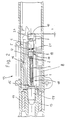
- the submachine gun shown in Figs. 1 to 4 has Housing 11, in which a barrel 13 is attached to the his rear end has a cartridge chamber in the a cartridge 14 is insertable. Behind the barrel 13 is a in the longitudinal direction movable, unlocked Closure 15 (ground closure) arranged in the housing 11th is guided and by a (not shown) closing spring pushed forward and against the barrel 13. Laterally from the shutter 15, when this in its front End position is an ejection window 12 in the housing 11th educated.
- the shutter 15, which is also shown in Fig. 5, is in the middle of the length of a firing pin 3 interspersed, which loads a firing pin spring 1 to the rear in such a way, that he seeks to take a position in which the Rear striker end 10 from the rear End face of the closure 15 by a supernatant Y after protrudes behind (Fig. 3).
- a cock 9 pivotally mounted which in Figs. 3 and 4 is indicated only very schematically.
- This cock 9 can be from a clamping position, in which its upper end with Distance behind the front end position of the closure is arranged (Fig. 3) in a tee-off position, which is shown in Fig. 4 and in which the cock 9 on the to the rear beyond the closure 15 projecting, rear Striker end 10 hits; This will be the Firing pin 3 thrown forward, hits the Primer of the cartridge 14 and fires this off (Fig. 4).
- a weapon is from the state of the art known.
- the closure 15 is also an extractor and Safety device in the form of a leaf spring 16th attached, whose rear end has a projection, engages in front of an end collar 20 of the firing pin 3 and prevents this from moving forward.
- the tee off Cock 9 meets an inclined surface on the leaf spring 16th and deflects them so that their projection from the Engagement with the collar 20 is moved and only then Firing pin immediately before the hammer is hit 9 is released.
- This leaf spring 16 is in German Patent application 197 02 374.6-15 described by the applicant; the disclosure of this patent application is by the Reference expressly included in the present documentation added.
- this leaf spring is the 16th modified so that they do not the firing pin 3 in completely fixed his backward situation, but one to him certain mobility (over the route X + Y) in Leads longitudinally forward.
- the firing pin 3 is from the leaf spring 16, however, still prevented with its tip over the front face of the Fastener 15 move out, as long as not the cock 9 by its knocking off the leaf spring 16 from the engagement with the firing pin 3 has pressed.
- the front end of the Leaf spring 16 is designed as an extractor.
- the closure On the leaf spring 16 opposite longitudinal side the closure has a in the front end face opening longitudinal groove 18, in which a Ausierervorsprung 17 engages the stationary at a, in the housing 11th fixed engaging part 8 is formed, which as Sheet steel component is formed, with its front End in a recess in the outside of the barrel 13 engages near the rear end.
- the firing pin 3 points, seen from the front to the rear (in the drawing from left to right), a thin point on, subsequently a thicker, but slender shaft, the approximately to the middle of the length extension of the firing pin 3 ranges, followed by a thickened, cylindrical Section 21 and finally the already mentioned Endbund 20.
- the firing pin spring 1 is on the slender shaft guided and supported with its rear end on the Paragraph, which marks the transition between the slender stem and the thickened portion 21 forms.
- the sleeve 4 and the stop piece 6 each have one lateral projection on, which is guided in the longitudinal groove 18 is; In addition, the stop piece 6 is stationary in the lock 15 held by a mounting pin 7.
- the sleeve 4 has, starting from the rear end surface, a Blind hole on, as well as the stopper piece 6, in which the blind bore from the front end surface starting.
- the Counter spring 5 penetrates into each of the blind holes and rests on the respective bore end face.
- the sleeve 4 sits with its front end surface a paragraph in the longitudinal bore in the closure 15.
- the Striker pin 1 is supported by its front end another paragraph in said longitudinal bore from, with its rear end on the heel of the firing pin.
- the opposing spring 5 is stronger than the firing pin spring 1, so that the opposing spring 5 is always the sleeve 4 against the effect seeks to push the firing pin spring 1 forward. If the closure is e.g. removed from the weapon, as in Fig. 5, then the sleeve 4 sits on the associated Paragraph of the closure longitudinal bore on and presses the Circlip 2 and thus the firing pin 3 forward, so that the rear firing pin end 10 by the dimension X towards the rear end of the shutter 15 forward is offset. In this position of the Schagbolzens 3, the e.g. is shown in Fig. 2, the tap 9 hits when knocked off on the rear surface of the shutter 15, without the rear striker end 10 to achieve.
- the housing 11 On the inside of the ejection window the housing 11 has a stationary engagement part 8 Sheet steel on, with a projection 17 in the longitudinal groove 18 of the shutter 15 is immersed.
- the leading edge 19 of this Projection 17 forms the ejector edge; if the shutter 15 with a cartridge 14 or an empty cartridge case moved backwards, then the edge of this hits Cartridge 14 or cartridge case on the ejection window 12 opposite side on the ejector edge 19 and is ejected by this.
- the projection 17 On the opposite of the ejector edge 19 Rear side, the projection 17 has another Function edge, which is set up in the engage lateral projection of the sleeve 4 and then this and thus the sleeve 4 at another To prevent forward movement.
- This functional edge of the Engagement part 8 meets the lateral projection of Sleeve 4 on, when the shutter is still around the distance X + Y of his front end position is removed, which he shot should take.
- the front end of the engaging part 8 engages in one Recess of the barrel 13, so that the rear Function edge of the projection 17 is always in fixed distance from the barrel 13 and thus of the The situation remains that the bottom of the cartridge 14 at gunpoint occupies.
- the leaf spring 16 engages with the projection in her rear area the collar 20 of the firing pin 3.
- the sleeve 4 is in its front end position and takes it over the locking ring 2 the firing pin 3 so far front, that is its rear end 10 around the distance X opposite the front end of the shutter 15 is moved forward is. Should now stop the tap 9 accidentally, then he would hit the back end of the shutter 15, but do not touch the firing pin 3.
- the in the longitudinal groove 18 guided lateral projection of the sleeve 4 is of the rear functional edge of the projection 17 of the Engaging part 8 removed by the distance Z, the Closure must cover at least, without the Cartridge 14 may be fired.
- top o. The like. go out from the horizontal position of use of the weapon when Shot, wherein the weft direction points to "front” (in the Drawing to the left).
- a breaker mechanism is provided, which is the triggering Connection between the trigger and the tap only then produces or with continuous fire the cock only then triggers, when the shutter is fully closed. This will be this Breaker mechanism by the position of the closure activated, so that basically the delivery of a shot only possible if the shutter completely closed is.
Landscapes
- Engineering & Computer Science (AREA)
- General Engineering & Computer Science (AREA)
- Portable Nailing Machines And Staplers (AREA)
- Ignition Installations For Internal Combustion Engines (AREA)
- Percussive Tools And Related Accessories (AREA)
- Pistons, Piston Rings, And Cylinders (AREA)
- Spark Plugs (AREA)
- Mechanical Coupling Of Light Guides (AREA)
- Toys (AREA)
Claims (4)
- Arme à feu de poing à chargement automatique comprenantcaractérisée en ce que l'arme à feu de poing à chargement automatique est équipée égalementune culasse (15), qui est mobile dans un carter (11) et peut se déplacer dans une position extrême aménagée pour l'allumage d'une cartouche (14),un percuteur (3) logé dans la culasse (15) de façon mobile le long d'une trajectoire de déplacement avec un ressort du percuteur (1) sollicitant ce percuteur vers l'arrière,un système de décrochage (9) qui peut être déclenché par un système de détente et est aménagé pour percuter, pour l'allumage d'une cartouche (14), sur l'extrémité du percuteur (10) opposée à cette cartouche et amener de ce fait le percuteur dans sa position d'allumage,d'un contre-ressort (5), qui s'appuie entre la culasse (15) et le percuteur (3) et appuie ce percuteur dans le sens contraire au sens de sollicitation par le ressort du percuteur (1) avec la culasse ouverte en le faisant sortir de la zone d'action du système de décrochage, etd'une réalisation solidaire du carter, qui n'agit qu'à la fin du mouvement de fermeture de la culasse (15) sur le contre-ressort (5) de telle sorte que celui-ci libère le percuteur (3) assez largement pour que celui-ci arrive dans la zone d'action du système de décrochage (9).
- Arme à feu de poing selon la revendication 1, caractérisée en ce que le percuteur (3) peut être amené dans une position le long de sa trajectoire de déplacement, dans laquelle son extrémité (10) tournée vers le système de décrochage (9) repose dans le cadre d'une réalisation de la culasse (15) dans une position de sécurité qui le protège de l'effet du système de décrochage (9).
- Arme à feu de poing selon les revendications 1 et 2, caractérisée en ce que la réalisation solidaire du carter forme une saillie (17), qui est conçue sur un composant (8) fixé séparément du carter (11), lequel s'engage de préférence dans le canon (13).
- Arme à feu de poing selon la revendication 3, caractérisée en ce que la saillie (17) présente deux arêtes s'étendant transversalement à la trajectoire de déplacement de la culasse (15), arêtes dont celle opposée au canon (13) forme la réalisation solidaire du boítier et celle tournée vers le canon (13) forme l'éjecteur.
Priority Applications (1)
| Application Number | Priority Date | Filing Date | Title |
|---|---|---|---|
| DK99908800T DK1064514T3 (da) | 1998-03-24 | 1999-01-19 | Slagboltstyring |
Applications Claiming Priority (3)
| Application Number | Priority Date | Filing Date | Title |
|---|---|---|---|
| DE19812951A DE19812951C2 (de) | 1998-03-24 | 1998-03-24 | Schlagbolzensicherung im Verschluß |
| DE19812951 | 1998-03-24 | ||
| PCT/EP1999/000294 WO1999049272A1 (fr) | 1998-03-24 | 1999-01-19 | Commande de gachette |
Publications (2)
| Publication Number | Publication Date |
|---|---|
| EP1064514A1 EP1064514A1 (fr) | 2001-01-03 |
| EP1064514B1 true EP1064514B1 (fr) | 2005-03-30 |
Family
ID=7862155
Family Applications (1)
| Application Number | Title | Priority Date | Filing Date |
|---|---|---|---|
| EP99908800A Expired - Lifetime EP1064514B1 (fr) | 1998-03-24 | 1999-01-19 | Commande de gachette |
Country Status (7)
| Country | Link |
|---|---|
| US (1) | US6349495B1 (fr) |
| EP (1) | EP1064514B1 (fr) |
| AT (1) | ATE292273T1 (fr) |
| CA (1) | CA2325504C (fr) |
| DE (2) | DE19812951C2 (fr) |
| ES (1) | ES2238824T3 (fr) |
| WO (1) | WO1999049272A1 (fr) |
Families Citing this family (18)
| Publication number | Priority date | Publication date | Assignee | Title |
|---|---|---|---|---|
| FI107759B (fi) * | 1999-12-03 | 2001-09-28 | Sako Oy | Aseen lukitusmenetelmä ja -järjestely |
| US20050115127A1 (en) * | 2003-02-19 | 2005-06-02 | Atilla Szabo | Extractor assembly for a semi-automatic handgun |
| DE20304023U1 (de) * | 2003-03-12 | 2003-05-22 | Röhm GmbH, 89567 Sontheim | Hunde-Trainingsgerät |
| AT413443B (de) * | 2003-03-13 | 2006-02-15 | Gen Headquarters Of The Armed | Pistole mit schlagbolzensicherung und auswerfer |
| DE102006037306B4 (de) | 2006-08-08 | 2009-12-03 | Rheinmetall Waffe Munition Gmbh | Vorrichtung zur Auslösung eines Schlagbolzens |
| US20100071541A1 (en) * | 2008-09-23 | 2010-03-25 | Browning | Firearm having an improved gas-operated action |
| US20100275486A1 (en) * | 2008-09-23 | 2010-11-04 | Browning | Shotgun having an improved shotshell feeding mechanism |
| US8079168B2 (en) * | 2008-09-23 | 2011-12-20 | Browning | Firearm having an improved firing pin locking mechanism |
| US8056280B2 (en) * | 2008-09-23 | 2011-11-15 | Browning | Firearm having an improved forearm fastening mechanism |
| US7963061B2 (en) * | 2008-09-23 | 2011-06-21 | Browning | Magazine plug |
| AT507219B1 (de) | 2008-12-09 | 2010-03-15 | Caracal Internat L L C | Pistole |
| US8296990B2 (en) | 2008-12-30 | 2012-10-30 | Smith & Wesson Corp. | Snap-on dovetail pistol sight |
| RU2443964C1 (ru) * | 2010-09-13 | 2012-02-27 | Открытое акционерное общество "Завод им. В.А. Дегтярева" | Автоматическое стрелковое оружие |
| WO2014107210A1 (fr) * | 2012-10-16 | 2014-07-10 | Coffman Ii Charles W | Système de rappel à ressort d'arme progressif avec rebond d'énergie élevé |
| US9810496B2 (en) * | 2014-05-15 | 2017-11-07 | Savage Arms, Inc. | Semiautomatic firearm |
| DE102014111160A1 (de) * | 2014-06-16 | 2015-12-17 | Rheinmetall Waffe Munition Gmbh | Sicherheitssystem für einen Verschluss einer Waffe |
| DE102015008797A1 (de) * | 2015-07-10 | 2017-01-12 | Rheinmetall Waffe Munition Gmbh | Hülsenauswurfvorrichtung |
| US10907918B2 (en) | 2019-03-20 | 2021-02-02 | Smith & Wesson Inc. | Cartridge extractor |
Family Cites Families (17)
| Publication number | Priority date | Publication date | Assignee | Title |
|---|---|---|---|---|
| DE201609C (fr) * | ||||
| DE107213C (fr) * | ||||
| NL2787C (fr) * | 1913-03-31 | |||
| US1455881A (en) * | 1917-07-20 | 1923-05-22 | Alva C Washburne | Firearm |
| US1363040A (en) * | 1917-12-01 | 1920-12-21 | Alva C Washburne | Firearm |
| US3889412A (en) * | 1973-11-26 | 1975-06-17 | Joseph E Filecci | Double action trigger mechanism for semi-automatic pistol |
| US3915811A (en) * | 1974-10-16 | 1975-10-28 | Oxy Metal Industries Corp | Method and composition for electroplating aluminum alloys |
| US4031648A (en) * | 1975-12-29 | 1977-06-28 | Thomas Frank S | Magazine safety and ejector |
| US4389919A (en) * | 1980-02-14 | 1983-06-28 | Remington Arms Company, Inc. | Firing pin block for firearm with a rotary breech bolt |
| US4589327A (en) * | 1983-03-28 | 1986-05-20 | Smith David E | Firing lock with safety system for self loading fire arms |
| DE3523531A1 (de) | 1984-07-02 | 1986-02-13 | Honda Giken Kogyo K.K., Tokio/Tokyo | Ventilbetaetigungseinrichtung mit sperrfunktion fuer einen verbrennungsmotor |
| US4726136A (en) * | 1984-08-22 | 1988-02-23 | Dornaus & Dixon Enterprises | Firearm safety devices |
| CH662876A5 (de) * | 1984-10-25 | 1987-10-30 | Haemmerli Ag | Abzugvorrichtung an einer faustfeuerwaffe. |
| EP0192343A3 (fr) * | 1985-02-04 | 1987-05-20 | Victory Arms Co. Limited | Système de sécurité pour le mécanisme de mise à feu d'une arme semi-automatique |
| DE3504519A1 (de) * | 1985-02-09 | 1986-08-14 | Mauser-Werke Oberndorf Gmbh, 7238 Oberndorf | Schlagbolzensicherung fuer einen keilverschluss einer grosskalibrigen rohrwaffe |
| EP0751366A1 (fr) * | 1995-06-30 | 1997-01-02 | Israel Military Industries Ltd. | Pistolet à double action comportant un méchanisme de décrochement du chien |
| DE19702374C2 (de) * | 1997-01-23 | 2001-03-01 | Heckler & Koch Gmbh | Schlagbolzensicherung für eine Abzugseinrichtung mit Schlagstück |
-
1998
- 1998-03-24 DE DE19812951A patent/DE19812951C2/de not_active Expired - Fee Related
-
1999
- 1999-01-19 AT AT99908800T patent/ATE292273T1/de not_active IP Right Cessation
- 1999-01-19 WO PCT/EP1999/000294 patent/WO1999049272A1/fr not_active Ceased
- 1999-01-19 ES ES99908800T patent/ES2238824T3/es not_active Expired - Lifetime
- 1999-01-19 CA CA002325504A patent/CA2325504C/fr not_active Expired - Fee Related
- 1999-01-19 EP EP99908800A patent/EP1064514B1/fr not_active Expired - Lifetime
- 1999-01-19 DE DE59911843T patent/DE59911843D1/de not_active Expired - Fee Related
-
2000
- 2000-09-22 US US09/669,064 patent/US6349495B1/en not_active Expired - Fee Related
Also Published As
| Publication number | Publication date |
|---|---|
| CA2325504C (fr) | 2005-06-28 |
| DE19812951C2 (de) | 2002-12-19 |
| DE19812951A1 (de) | 1999-09-30 |
| CA2325504A1 (fr) | 1999-09-30 |
| ES2238824T3 (es) | 2005-09-01 |
| ATE292273T1 (de) | 2005-04-15 |
| WO1999049272A1 (fr) | 1999-09-30 |
| EP1064514A1 (fr) | 2001-01-03 |
| US6349495B1 (en) | 2002-02-26 |
| DE59911843D1 (de) | 2005-05-04 |
Similar Documents
| Publication | Publication Date | Title |
|---|---|---|
| EP1064514B1 (fr) | Commande de gachette | |
| EP0816792B1 (fr) | Mécanisme de détente | |
| DE19702374C2 (de) | Schlagbolzensicherung für eine Abzugseinrichtung mit Schlagstück | |
| EP1119736B1 (fr) | Dispositif de detente | |
| DE2442107A1 (de) | Halbautomatische feuerwaffe | |
| DE3505443C2 (fr) | ||
| EP0540778A1 (fr) | Mécanisme de détente pour armes à feu | |
| DE102014102672B4 (de) | Feuerwaffe, insbesondere Handfeuerwaffe, sowie Verfahren zur Herstellung einer Feuerwaffe | |
| EP4038335B1 (fr) | Arme à feu dotée d'un éjecteur | |
| DE2745670A1 (de) | Abzugssicherung fuer schusswaffen | |
| EP1825207A1 (fr) | Arme a feu de poing a repetition | |
| DE19959964B4 (de) | Sicherung | |
| EP0895053B1 (fr) | Mécanisme de mise à feu à double action | |
| EP3176536B1 (fr) | Culasse pour arme et arme de poing dotée d'une telle culasse | |
| DE19605851C2 (de) | Sicherung eines Schlagbolzens einer Schlagbolzen- und Schlagstückeinrichtung für eine Schußwaffe | |
| DE102019124569B4 (de) | Schlosssystem | |
| EP2109747B1 (fr) | Bloc de culasse pour une arme à canon basculant | |
| EP1535012B1 (fr) | Arme a feu de poing a culasse verrouillee | |
| DE4013124C2 (de) | Schlagbolzensicherung mit integrierter Fallsicherung | |
| DE1166052B (de) | Einsatzgeraet mit Einstecklauf zum Verschiessen von Kleinkaliber-Munition durch automatische Handfeuerwaffen, insbesondere Sturmgewehre mit Hammerzuendung | |
| DE3323501C2 (de) | Handfeuerwaffe | |
| DE19500140A1 (de) | Gewehr mit Doppelfunktionsabzug | |
| DE69003551T2 (de) | Sicherheitsvorrichtung für den Fall des Auftreffens auf eine durch eine Sprengstoffpatrone angetriebene Vorrichtung. | |
| DE139766C (de) | Selbsttätige Feuerwaffe mit gleitendem Lauf | |
| DE7721573U1 (de) | Wiederspannabzug |
Legal Events
| Date | Code | Title | Description |
|---|---|---|---|
| PUAI | Public reference made under article 153(3) epc to a published international application that has entered the european phase |
Free format text: ORIGINAL CODE: 0009012 |
|
| 17P | Request for examination filed |
Effective date: 20000913 |
|
| AK | Designated contracting states |
Kind code of ref document: A1 Designated state(s): AT BE CH DE DK ES FR GB IT LI NL |
|
| GRAP | Despatch of communication of intention to grant a patent |
Free format text: ORIGINAL CODE: EPIDOSNIGR1 |
|
| GRAS | Grant fee paid |
Free format text: ORIGINAL CODE: EPIDOSNIGR3 |
|
| GRAA | (expected) grant |
Free format text: ORIGINAL CODE: 0009210 |
|
| AK | Designated contracting states |
Kind code of ref document: B1 Designated state(s): AT BE CH DE DK ES FR GB IT LI NL |
|
| REG | Reference to a national code |
Ref country code: GB Ref legal event code: FG4D Free format text: NOT ENGLISH |
|
| REG | Reference to a national code |
Ref country code: CH Ref legal event code: NV Representative=s name: E. BLUM & CO. PATENTANWAELTE Ref country code: CH Ref legal event code: EP |
|
| GBT | Gb: translation of ep patent filed (gb section 77(6)(a)/1977) |
Effective date: 20050330 |
|
| REF | Corresponds to: |
Ref document number: 59911843 Country of ref document: DE Date of ref document: 20050504 Kind code of ref document: P |
|
| REG | Reference to a national code |
Ref country code: DK Ref legal event code: T3 |
|
| REG | Reference to a national code |
Ref country code: ES Ref legal event code: FG2A Ref document number: 2238824 Country of ref document: ES Kind code of ref document: T3 |
|
| PLBE | No opposition filed within time limit |
Free format text: ORIGINAL CODE: 0009261 |
|
| STAA | Information on the status of an ep patent application or granted ep patent |
Free format text: STATUS: NO OPPOSITION FILED WITHIN TIME LIMIT |
|
| ET | Fr: translation filed | ||
| 26N | No opposition filed |
Effective date: 20060102 |
|
| REG | Reference to a national code |
Ref country code: CH Ref legal event code: PFA Owner name: HECKLER & KOCH GMBH Free format text: HECKLER & KOCH GMBH#ALTE STEIGE 7#78727 OBERNDORF (DE) -TRANSFER TO- HECKLER & KOCH GMBH#ALTE STEIGE 7#78727 OBERNDORF (DE) |
|
| PGFP | Annual fee paid to national office [announced via postgrant information from national office to epo] |
Ref country code: ES Payment date: 20090126 Year of fee payment: 11 Ref country code: DK Payment date: 20090122 Year of fee payment: 11 Ref country code: AT Payment date: 20090122 Year of fee payment: 11 |
|
| PGFP | Annual fee paid to national office [announced via postgrant information from national office to epo] |
Ref country code: NL Payment date: 20090122 Year of fee payment: 11 |
|
| PGFP | Annual fee paid to national office [announced via postgrant information from national office to epo] |
Ref country code: GB Payment date: 20090123 Year of fee payment: 11 Ref country code: CH Payment date: 20090126 Year of fee payment: 11 |
|
| PGFP | Annual fee paid to national office [announced via postgrant information from national office to epo] |
Ref country code: BE Payment date: 20090129 Year of fee payment: 11 |
|
| PGFP | Annual fee paid to national office [announced via postgrant information from national office to epo] |
Ref country code: IT Payment date: 20090124 Year of fee payment: 11 Ref country code: DE Payment date: 20090320 Year of fee payment: 11 |
|
| PGFP | Annual fee paid to national office [announced via postgrant information from national office to epo] |
Ref country code: FR Payment date: 20090120 Year of fee payment: 11 |
|
| BERE | Be: lapsed |
Owner name: *HECKLER & KOCH G.M.B.H. Effective date: 20100131 |
|
| REG | Reference to a national code |
Ref country code: NL Ref legal event code: V1 Effective date: 20100801 |
|
| REG | Reference to a national code |
Ref country code: CH Ref legal event code: PL |
|
| REG | Reference to a national code |
Ref country code: DK Ref legal event code: EBP |
|
| GBPC | Gb: european patent ceased through non-payment of renewal fee |
Effective date: 20100119 |
|
| REG | Reference to a national code |
Ref country code: FR Ref legal event code: ST Effective date: 20100930 |
|
| PG25 | Lapsed in a contracting state [announced via postgrant information from national office to epo] |
Ref country code: NL Free format text: LAPSE BECAUSE OF NON-PAYMENT OF DUE FEES Effective date: 20100801 Ref country code: LI Free format text: LAPSE BECAUSE OF NON-PAYMENT OF DUE FEES Effective date: 20100131 Ref country code: FR Free format text: LAPSE BECAUSE OF NON-PAYMENT OF DUE FEES Effective date: 20100201 Ref country code: CH Free format text: LAPSE BECAUSE OF NON-PAYMENT OF DUE FEES Effective date: 20100131 |
|
| PG25 | Lapsed in a contracting state [announced via postgrant information from national office to epo] |
Ref country code: DE Free format text: LAPSE BECAUSE OF NON-PAYMENT OF DUE FEES Effective date: 20100803 Ref country code: AT Free format text: LAPSE BECAUSE OF NON-PAYMENT OF DUE FEES Effective date: 20100119 |
|
| PG25 | Lapsed in a contracting state [announced via postgrant information from national office to epo] |
Ref country code: GB Free format text: LAPSE BECAUSE OF NON-PAYMENT OF DUE FEES Effective date: 20100119 |
|
| PG25 | Lapsed in a contracting state [announced via postgrant information from national office to epo] |
Ref country code: DK Free format text: LAPSE BECAUSE OF NON-PAYMENT OF DUE FEES Effective date: 20100131 |
|
| PG25 | Lapsed in a contracting state [announced via postgrant information from national office to epo] |
Ref country code: BE Free format text: LAPSE BECAUSE OF NON-PAYMENT OF DUE FEES Effective date: 20100131 |
|
| REG | Reference to a national code |
Ref country code: ES Ref legal event code: FD2A Effective date: 20110224 |
|
| PG25 | Lapsed in a contracting state [announced via postgrant information from national office to epo] |
Ref country code: IT Free format text: LAPSE BECAUSE OF NON-PAYMENT OF DUE FEES Effective date: 20100119 |
|
| PG25 | Lapsed in a contracting state [announced via postgrant information from national office to epo] |
Ref country code: ES Free format text: LAPSE BECAUSE OF NON-PAYMENT OF DUE FEES Effective date: 20110223 |
|
| PG25 | Lapsed in a contracting state [announced via postgrant information from national office to epo] |
Ref country code: ES Free format text: LAPSE BECAUSE OF NON-PAYMENT OF DUE FEES Effective date: 20100120 |