EP1064724B1 - Filtre acoustique a ondes de surface - Google Patents
Filtre acoustique a ondes de surface Download PDFInfo
- Publication number
- EP1064724B1 EP1064724B1 EP99922063A EP99922063A EP1064724B1 EP 1064724 B1 EP1064724 B1 EP 1064724B1 EP 99922063 A EP99922063 A EP 99922063A EP 99922063 A EP99922063 A EP 99922063A EP 1064724 B1 EP1064724 B1 EP 1064724B1
- Authority
- EP
- European Patent Office
- Prior art keywords
- transducer
- transducers
- acoustic wave
- surface acoustic
- filter
- Prior art date
- Legal status (The legal status is an assumption and is not a legal conclusion. Google has not performed a legal analysis and makes no representation as to the accuracy of the status listed.)
- Expired - Lifetime
Links
- 238000010897 surface acoustic wave method Methods 0.000 claims description 13
- 230000001939 inductive effect Effects 0.000 claims description 10
- 230000008878 coupling Effects 0.000 claims description 7
- 238000010168 coupling process Methods 0.000 claims description 7
- 238000005859 coupling reaction Methods 0.000 claims description 7
- 230000004907 flux Effects 0.000 claims description 4
- 230000002411 adverse Effects 0.000 description 2
- 230000005540 biological transmission Effects 0.000 description 2
- 230000000903 blocking effect Effects 0.000 description 2
- 230000001419 dependent effect Effects 0.000 description 2
- 230000007246 mechanism Effects 0.000 description 2
- 230000001771 impaired effect Effects 0.000 description 1
- 230000010363 phase shift Effects 0.000 description 1
- 238000000926 separation method Methods 0.000 description 1
Images


Classifications
-
- H—ELECTRICITY
- H03—ELECTRONIC CIRCUITRY
- H03H—IMPEDANCE NETWORKS, e.g. RESONANT CIRCUITS; RESONATORS
- H03H9/00—Networks comprising electromechanical or electro-acoustic elements; Electromechanical resonators
- H03H9/46—Filters
- H03H9/64—Filters using surface acoustic waves
- H03H9/6423—Means for obtaining a particular transfer characteristic
- H03H9/6433—Coupled resonator filters
- H03H9/6479—Capacitively coupled SAW resonator filters
-
- H—ELECTRICITY
- H03—ELECTRONIC CIRCUITRY
- H03H—IMPEDANCE NETWORKS, e.g. RESONANT CIRCUITS; RESONATORS
- H03H9/00—Networks comprising electromechanical or electro-acoustic elements; Electromechanical resonators
- H03H9/0023—Networks for transforming balanced signals into unbalanced signals and vice versa, e.g. baluns, or networks having balanced input and output
- H03H9/0028—Networks for transforming balanced signals into unbalanced signals and vice versa, e.g. baluns, or networks having balanced input and output using surface acoustic wave devices
- H03H9/0033—Networks for transforming balanced signals into unbalanced signals and vice versa, e.g. baluns, or networks having balanced input and output using surface acoustic wave devices having one acoustic track only
- H03H9/0038—Networks for transforming balanced signals into unbalanced signals and vice versa, e.g. baluns, or networks having balanced input and output using surface acoustic wave devices having one acoustic track only the balanced terminals being on the same side of the track
-
- H—ELECTRICITY
- H03—ELECTRONIC CIRCUITRY
- H03H—IMPEDANCE NETWORKS, e.g. RESONANT CIRCUITS; RESONATORS
- H03H9/00—Networks comprising electromechanical or electro-acoustic elements; Electromechanical resonators
- H03H9/02—Details
- H03H9/02535—Details of surface acoustic wave devices
- H03H9/02637—Details concerning reflective or coupling arrays
- H03H9/02685—Grating lines having particular arrangements
- H03H9/02716—Tilted, fan shaped or slanted grating lines
-
- H—ELECTRICITY
- H03—ELECTRONIC CIRCUITRY
- H03H—IMPEDANCE NETWORKS, e.g. RESONANT CIRCUITS; RESONATORS
- H03H9/00—Networks comprising electromechanical or electro-acoustic elements; Electromechanical resonators
- H03H9/02—Details
- H03H9/02535—Details of surface acoustic wave devices
- H03H9/02637—Details concerning reflective or coupling arrays
- H03H9/02795—Multi-strip couplers as track changers
-
- H—ELECTRICITY
- H03—ELECTRONIC CIRCUITRY
- H03H—IMPEDANCE NETWORKS, e.g. RESONANT CIRCUITS; RESONATORS
- H03H9/00—Networks comprising electromechanical or electro-acoustic elements; Electromechanical resonators
- H03H9/02—Details
- H03H9/02535—Details of surface acoustic wave devices
- H03H9/02818—Means for compensation or elimination of undesirable effects
- H03H9/02874—Means for compensation or elimination of undesirable effects of direct coupling between input and output transducers
-
- H—ELECTRICITY
- H03—ELECTRONIC CIRCUITRY
- H03H—IMPEDANCE NETWORKS, e.g. RESONANT CIRCUITS; RESONATORS
- H03H9/00—Networks comprising electromechanical or electro-acoustic elements; Electromechanical resonators
- H03H9/02—Details
- H03H9/125—Driving means, e.g. electrodes, coils
- H03H9/145—Driving means, e.g. electrodes, coils for networks using surface acoustic waves
- H03H9/14544—Transducers of particular shape or position
- H03H9/14588—Horizontally-split transducers
-
- H—ELECTRICITY
- H03—ELECTRONIC CIRCUITRY
- H03H—IMPEDANCE NETWORKS, e.g. RESONANT CIRCUITS; RESONATORS
- H03H9/00—Networks comprising electromechanical or electro-acoustic elements; Electromechanical resonators
- H03H9/46—Filters
- H03H9/64—Filters using surface acoustic waves
- H03H9/6423—Means for obtaining a particular transfer characteristic
- H03H9/6433—Coupled resonator filters
- H03H9/644—Coupled resonator filters having two acoustic tracks
- H03H9/6443—Coupled resonator filters having two acoustic tracks being acoustically coupled
- H03H9/6453—Coupled resonator filters having two acoustic tracks being acoustically coupled by at least an interdigital transducer overlapping both tracks
-
- H—ELECTRICITY
- H03—ELECTRONIC CIRCUITRY
- H03H—IMPEDANCE NETWORKS, e.g. RESONANT CIRCUITS; RESONATORS
- H03H9/00—Networks comprising electromechanical or electro-acoustic elements; Electromechanical resonators
- H03H9/46—Filters
- H03H9/64—Filters using surface acoustic waves
- H03H9/6423—Means for obtaining a particular transfer characteristic
- H03H9/6433—Coupled resonator filters
- H03H9/644—Coupled resonator filters having two acoustic tracks
- H03H9/6456—Coupled resonator filters having two acoustic tracks being electrically coupled
- H03H9/6459—Coupled resonator filters having two acoustic tracks being electrically coupled via one connecting electrode
- H03H9/6463—Coupled resonator filters having two acoustic tracks being electrically coupled via one connecting electrode the tracks being electrically cascaded
Definitions
- SAW filter surface acoustic wave filter
- both mechanisms i. inductive and capacitive crosstalk
- Their respective levels of electromagnetic crosstalk depend on the filter parameters, with increasingly high inductive crosstalk becoming more important at high frequencies and lower impedances.
- Typical SAW filters whose blocking selection is considerably impaired by electromagnetic crosstalk are acoustically transversely coupled filters, eg symmetrically operated filters Transverse mode coupled resonator filters (also called TCR filters) of the type described in "1996 IEEE Ultrasonics Symposium - 47 - 51".
- filters eg symmetrically operated filters
- Transverse mode coupled resonator filters also called TCR filters
- the input or output transducers are along their longitudinal, i. splitted in the direction of the acoustic track, the partial transducers thus obtained are electrically connected in series.
- the capacitive crosstalk between the split partial transducers and the transducer element directly adjacent in the adjacent acoustic track can be compensated.
- This requires symmetrical operation on at least one filter port, i. at least at the input or output transducer. In this case, due to the different polarity of the applied voltages and the same amount of the spare capacity, the crosstalk is canceled.
- the impedance of the corresponding terminals increases to twice the output value.
- a surface acoustic wave filter with capacitive crosstalk compensation between the transducers is known from GB 1 427 226 A.
- the present invention has for its object to provide an acoustic SAW filter with at least two electromagnetically coupled transducers, in which the capacitive and inductive crosstalk is compensated, and thus has a significantly improved compared to the known filters locking selection without the impedance to increase.
- the invention provides a surface acoustic wave filter which is symmetrically operable having electromagnetically coupled interdigital transducers in adjacent acoustic tracks, in which at least one of the electromagnetically coupled transducers is divided into parallel-connected partial transducers, wherein the partial transducers and busbars of the transducers are arranged such that that in the case of symmetrical operation, the crosstalk capacitances between adjacent busbars and IDT transducers at the corresponding port are applied to the same magnitude but with differently signed voltages and are thus adjusted.
- the at least one interdigital transducer is thus divided into partial transducers and modified the leadership of power supply rails of the converter so that also the flow directions of the magnetic couplings between the partial transducers and at least one transducer of the adjacent acoustic track are oppositely directed, so that the inductive crosstalk contributions cancel each other out.
- the two main causes for the crosstalk of the SAW filter are turned off and the transmission behavior is improved.
- the polarity of the electric drive is reversed in one of the partial transducers by the modified guidance of the busbars.
- the desired acoustic mode of operation of the filter is determined by mirroring the relevant partial transducer parallel to the preferred acoustic propagation direction, i. by reflection on its longitudinal axis, maintained.
- the permutation of the polarity of the electric drive is also achievable when a sub-converter is shifted against the other sub-converter by an odd multiple of half the wavelength of the surface acoustic wave.
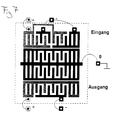
- FIGS. 1-10 Further features of a surface acoustic wave filter with compensation of capacitive and / or inductive crosstalk contributions are explained in FIGS.
- a transducer for example the input transducer, is divided longitudinally, but the partial transducers are not connected in series but in parallel. The occurring crossing of the tracks is resolved by a double bond to the housing.
- the two equivalent capacitances C4 and C4 'build up between the busbars of the partial transducers a and a' and the busbar 6 of the only transducer of the adjacent acoustic track which are approximately the same size and compensate each other due to the different polarities.
- the input impedance remains here by parallel connection of two partial transducers of an impedance of 2 Z w each on the reference value Z w .
- the impedance at the filter input is therefore not increased by the partial transducers.
- the compensation of the capacitances C4 and C4 ' is maintained even if the output is not operated symmetrically, that is, when a terminal is set to fixed potential (ground).
- the capacitive and the inductive crosstalk are equivalent circuit capacities C, C 'indicated by dashed lines or by magnetic field lines H, H 'symbolizes, which entwine partly marked by arrows adjacent Stromflußlinien.
- input and output transducers 10, 11 are arranged in mutually parallel acoustic tracks, which are coupled to one another via corresponding reflectors 12, 13 inclined to the main propagation direction of the acoustic tracks.
- both transducers whose current leads are designated 14, 15 and 16, 17, 18, respectively, are longitudinal, i. considered in the direction of the main propagation direction of the surface waves, split in partial transducers a, a 'and b, b' and their power supply lines 14, 15 and 16, 17, 18 so guided, that interchanged in one of the partial converter, the polarity of the electrical drive and so that current flow loops of different magnetic flux orientation - see the magnetic field lines H, H '- are obtained, which lead to the mutual cancellation of inductive crosstalk contributions.
- the parallel circuit of the partial transducers offers in contrast to the series circuit cheaper acoustic transducer resistors and in addition lower resistances of the power supply tracks and thus lower losses.
- the series circuit is characterized by smaller footprint and easier management of power outlets.
- the input transducer 20 is subdivided longitudinally into partial transducers d, d 'and the output transducer 23 coupled via reflectors 21, 22 into partial transducers e, e'.
- one partial transducer can be displaced against the other partial transducer by an odd multiple of half the wavelength of the surface acoustic wave.
- the power supply tracks 24, 25 and 26, 27 are again guided so that in one of the partial transducers, the polarity of the electrical drive reversed and thus different magnetic flux directions H, H 'are obtained, which lead to the compensation of the induced crosstalk contributions.
- both sub-converter pairs are connected in parallel.
- the thus created capacitive half-bridge for the crosstalk capacitances C, C ' is balanced again in symmetrical operation at the gate 23.
- Fig. 5 shows another filter implementation according to the invention.
- the inline filter according to FIG. 5 ie in the case of a filter with input and output transducers 30 or 31 arranged in the same acoustic track, only one of the two transducers, in this case the input transducer 30, is divided transversely into partial transducers f, f '.
- the sub-converter and the guidance of the power supply tracks 32, 33 in turn cause in the sense already explained above an adjustment of the crosstalk capacitances C, C 'and the compensation of the inductive crosstalk contributions.
- FIG 6 shows how the transducers (e.g., the transducers of Figure 2) can be cascaded to a higher order filter.
- Input and output side of the filter are constructed as in Figure 2.
- the coupling between the substructures is purely electrical via the two middle asymmetrically operated converter.
- the impedance Z connected to the two middle transducers serves to tune the transmission behavior of the overall filter.
- the division into parallel-connected partial transducers on the side designated here as input E compensates the capacitive crosstalk.
- the reactive capacitance C7 does not lead to crosstalk since the middle busbar is grounded.
- Figure 7 shows a filter in which all tracks are acoustically and not electrically coupled.
- the filter order can be increased by recording additional Resonatorspuren.
- the invention is not limited to the above embodiments, but is defined by the features in claim 1. Any combination of longitudinal / transversal converter split, parallel / series switching of the split transducers, and combinations of inline / transversal acoustic couplings are possible, as long as they have the features claimed in claim 1.
- the invention can also be used in TCF filters (Transversly Coupled Resonator Filters) in which the surface wave is not transmitted via inclined reflectors but directly into the adjacent tracks by acoustic coupling.
- TCF filters Transversly Coupled Resonator Filters
Landscapes
- Physics & Mathematics (AREA)
- Acoustics & Sound (AREA)
- Surface Acoustic Wave Elements And Circuit Networks Thereof (AREA)
Claims (6)
- Filtre acoustique à ondes de surface,- qui peut fonctionner symétriquement des deux côtés,- ayant des transducteurs (20, 23) interdigités et couplés électromagnétiquement,- dans lequel au moins l'un des transducteurs (20, 23) interdigités et couplés électromagnétiquement est décomposé en des sous-transducteurs (d, d'; f, f') montés en parallèle,- dans lequel les sous-transducteurs et les rails de connexion de courant des transducteurs (20, 23) interdigités sont disposés de sorte qu'en fonctionnement symétrique, les capacités de diaphonie entre des rails de connexion de courant, tournés l'un vers l'autre, des transducteurs interdigités et couplés électromagnétiquement s'appliquent à la porte correspondante en étant à peu prés égales en valeur absolue, mais de polarité opposée en tension et ainsi se compensent,- les rails (24, 25, 26, 27) de connexion de courant des transducteurs interdigités électromagnétiquement étant guidés de façon à obtenir des couplages magnétiques, ayant des directions (H, H') de flux magnétique de sens opposé, qui entraînent la compensation des contributions de diaphonie inductives induites.
- Filtre à ondes de surface selon la revendication 1, dans lequel les sous conducteurs (d, d') montés en parallèle sont disposés côte-à-côte dans des directions longitudinales.
- Filtre à ondes de surface selon la revendication 1 ou 2, dans lequel les deux transducteurs (20, 23) interdigités sont décomposés en des sous transducteurs (d, d'; e, e') montés en parallèle.
- Filtre à ondes de surface selon la revendication 1 à 2, dans lequel l'un des transducteurs interdigités et couplés électromagnétiquement est décomposé en des sous transducteurs montés en parallèle et dans lequel le transducteur interdigité qui lui est couplé est décomposé en des sous transducteurs montés en série.
- Filtre à ondes de surface selon les revendications 1 à 4, dans lequel un sous transducteur du transducteur interdigité décomposé est à distance de l'autre sous transducteur de ce transducteur, d'un multiple impair de la demi longueur d'onde de l'onde de surface accoustique.
- Filtre à ondes de surface selon la revendication 1 dans lequel au moins un transducteur interdigité est décomposé dans la direction transversale en sous transducteurs (f, f').
Applications Claiming Priority (3)
| Application Number | Priority Date | Filing Date | Title |
|---|---|---|---|
| DE19812641 | 1998-03-23 | ||
| DE19812641 | 1998-03-23 | ||
| PCT/DE1999/000843 WO1999049573A1 (fr) | 1998-03-23 | 1999-03-22 | Filtre acoustique a ondes de surface |
Publications (2)
| Publication Number | Publication Date |
|---|---|
| EP1064724A1 EP1064724A1 (fr) | 2001-01-03 |
| EP1064724B1 true EP1064724B1 (fr) | 2006-10-18 |
Family
ID=7861943
Family Applications (1)
| Application Number | Title | Priority Date | Filing Date |
|---|---|---|---|
| EP99922063A Expired - Lifetime EP1064724B1 (fr) | 1998-03-23 | 1999-03-22 | Filtre acoustique a ondes de surface |
Country Status (8)
| Country | Link |
|---|---|
| US (1) | US6441704B1 (fr) |
| EP (1) | EP1064724B1 (fr) |
| JP (1) | JP2002508615A (fr) |
| KR (1) | KR20010034613A (fr) |
| CN (1) | CN1294781A (fr) |
| CA (1) | CA2325434A1 (fr) |
| DE (1) | DE59913935D1 (fr) |
| WO (1) | WO1999049573A1 (fr) |
Families Citing this family (16)
| Publication number | Priority date | Publication date | Assignee | Title |
|---|---|---|---|---|
| DE10123369A1 (de) * | 2001-05-14 | 2002-12-05 | Infineon Technologies Ag | Filteranordnung für, symmetrische und unsymmetrische Leitungssysteme |
| EP1263137B1 (fr) * | 2001-05-31 | 2017-07-26 | Skyworks Filter Solutions Japan Co., Ltd. | Filtre à ondes acoustiques de surface, filtre de type équilibré et dispositif de communication |
| DE10163517B4 (de) * | 2001-12-14 | 2009-12-17 | Leibniz-Institut für Festkörper- und Werkstoffforschung e.V. | Resonatorfilterkaskade |
| WO2007007476A1 (fr) * | 2005-07-13 | 2007-01-18 | Murata Manufacturing Co., Ltd. | Filtre à onde acoustique d’interface |
| CN101326693B (zh) * | 2005-12-13 | 2010-10-27 | Abb技术有限公司 | 高压直流滤波器 |
| EP2168202B1 (fr) * | 2007-06-27 | 2013-07-31 | Superconductor Technologies, Inc. | Filtre de radiofréquence pouvant être syntonisé de faible perte |
| US8476991B2 (en) | 2007-11-06 | 2013-07-02 | Panasonic Corporation | Elastic wave resonator, elastic wave filter, and antenna sharing device using the same |
| JP4569713B2 (ja) * | 2007-11-06 | 2010-10-27 | パナソニック株式会社 | 弾性波共振器、弾性波フィルタおよびこれを用いたアンテナ共用器 |
| US7939989B2 (en) * | 2009-09-22 | 2011-05-10 | Triquint Semiconductor, Inc. | Piston mode acoustic wave device and method providing a high coupling factor |
| US8294331B2 (en) | 2009-09-22 | 2012-10-23 | Triquint Semiconductor, Inc. | Acoustic wave guide device and method for minimizing trimming effects and piston mode instabilities |
| DE102010008774B4 (de) | 2010-02-22 | 2015-07-23 | Epcos Ag | Mikroakustisches Filter mit kompensiertem Übersprechen und Verfahren zur Kompensation |
| WO2015033892A1 (fr) * | 2013-09-06 | 2015-03-12 | 株式会社村田製作所 | Résonateur à ondes acoustiques de surface, dispositif de filtre à ondes acoustiques de surface et duplexeur |
| WO2015033891A1 (fr) * | 2013-09-06 | 2015-03-12 | 株式会社村田製作所 | Résonateur à ondes acoustiques de surface, dispositif de filtre à ondes acoustiques de surface et duplexeur |
| DE112015003080B4 (de) | 2014-06-30 | 2018-06-21 | Snaptrack, Inc. | Rf-filterschaltung, rf-filter mit verbesserter dämpfung und duplexer mit verbesserter isolierung |
| US10236858B1 (en) * | 2015-08-26 | 2019-03-19 | Hrl Laboratories, Llc | Differential split-electrode feedthrough cancellation mechanism |
| CN114614791B (zh) * | 2022-05-12 | 2022-08-23 | 深圳新声半导体有限公司 | 级联谐振器和声表面波滤波器 |
Family Cites Families (9)
| Publication number | Priority date | Publication date | Assignee | Title |
|---|---|---|---|---|
| GB1427226A (en) * | 1973-06-05 | 1976-03-10 | Mullard Ltd | Acoustic surface wave devices |
| DE3942148A1 (de) | 1989-12-20 | 1991-06-27 | Siemens Ag | Oberflaechenwellen-reflektorfilter |
| DE4214122C2 (de) * | 1992-04-29 | 2001-02-22 | Siemens Ag | Zweispur-Oberflächenwellenanordnung mit verbesserter Selektionseigenschaft |
| FR2739232B1 (fr) * | 1995-09-26 | 1997-10-24 | Thomson Csf | Filtre a ondes acoustiques de surface utilisant le couplage de trois voies acoustiques |
| GB2306821B (en) * | 1995-11-03 | 2000-05-31 | Advanced Saw Prod Sa | Electro-acoustic device |
| EP0921636B1 (fr) * | 1996-05-23 | 2007-04-04 | Matsushita Electric Industrial Co., Ltd. | Filtre à ondes acoustiques de surface et filtre à ondes acoustiques de surface à plusieurs étages |
| DE19638455A1 (de) * | 1996-09-19 | 1998-04-02 | Siemens Matsushita Components | Twin-Dualmode-Filter |
| FR2762458B1 (fr) * | 1997-04-18 | 1999-07-09 | Thomson Csf | Dispositif a ondes acoustiques de surface a couplage par proximite a entrees/sorties differentielles |
| US6104260A (en) * | 1997-12-22 | 2000-08-15 | Matsushita Electric Industrial Co., Ltd. | Surface acoustic wave filter with first and second filter tracks and balanced or unbalanced terminals |
-
1999
- 1999-03-22 EP EP99922063A patent/EP1064724B1/fr not_active Expired - Lifetime
- 1999-03-22 CA CA002325434A patent/CA2325434A1/fr not_active Abandoned
- 1999-03-22 JP JP2000538432A patent/JP2002508615A/ja not_active Withdrawn
- 1999-03-22 CN CN99804380A patent/CN1294781A/zh active Pending
- 1999-03-22 KR KR1020007010487A patent/KR20010034613A/ko not_active Withdrawn
- 1999-03-22 WO PCT/DE1999/000843 patent/WO1999049573A1/fr not_active Ceased
- 1999-03-22 DE DE59913935T patent/DE59913935D1/de not_active Expired - Lifetime
-
2000
- 2000-09-25 US US09/668,490 patent/US6441704B1/en not_active Expired - Lifetime
Also Published As
| Publication number | Publication date |
|---|---|
| WO1999049573A1 (fr) | 1999-09-30 |
| KR20010034613A (ko) | 2001-04-25 |
| DE59913935D1 (de) | 2006-11-30 |
| CA2325434A1 (fr) | 1999-09-30 |
| US6441704B1 (en) | 2002-08-27 |
| JP2002508615A (ja) | 2002-03-19 |
| EP1064724A1 (fr) | 2001-01-03 |
| CN1294781A (zh) | 2001-05-09 |
Similar Documents
| Publication | Publication Date | Title |
|---|---|---|
| EP1064724B1 (fr) | Filtre acoustique a ondes de surface | |
| DE69413843T2 (de) | Oberflächenwellenresonatoren mit zwei moden | |
| DE19818038B4 (de) | Dualmode-Oberflächenwellenfilter | |
| EP0927458B1 (fr) | Filtre a ondes de surface pour mode de fonctionnement asymetrique/symetrique et symetrique/symetrique | |
| DE69827187T2 (de) | Akustische Oberflächenwellenanordnung mit Nahfeldkopplung und differentiellen Ein- und Ausgängen | |
| DE102010046087A1 (de) | Piston-Mode-Akustikwellenvorrichtung und Verfahren, das einen hohen Kopplungsfaktor liefert | |
| WO2007104283A1 (fr) | Filtre DMS avec résonateurs commutés | |
| DE102018130144A1 (de) | Elektroakustischer Resonator und HF-Filter | |
| DE2133634A1 (de) | Elektrisches filter nach dem oberflaechenwellenprinzip | |
| DE102004020183A1 (de) | Oberflächenwellen-Resonatorfilter mit longitudinal gekoppelten Wandlern | |
| EP0927456B1 (fr) | Filtres jumeles du type bimode | |
| DE102005010658A1 (de) | Duplexer mit verbesserter Leistungsverträglichkeit | |
| EP0709957B1 (fr) | Composant à ondes acoustiques de surface et son procédé de fabrication | |
| DE102010005306B4 (de) | DMS Filter mit verbesserter Signalunterdrückung | |
| DE10026074B4 (de) | Rekursives OFW-Filter mit geringer Chiplänge | |
| DE10352640B4 (de) | DMS-Filter | |
| DE102004048715B4 (de) | SAW-Filter mit Impedanz-Transformation | |
| DE10025450B4 (de) | Oberflächenwellen-Bandpassfilter in Drei-Wandler-Anordnung | |
| DE19724255C2 (de) | Transversalmodenresonatorfilter | |
| DE102016106185A1 (de) | Breitbandiges SAW-Filter | |
| DE19638398C2 (de) | Oberflächenwellen-Bauelement | |
| DE10159449B4 (de) | Schaltbares Oberflächenwellenfilter | |
| DE2829655C2 (de) | Elektromechanisches Filter | |
| DE19900326C2 (de) | Transversalmodenresonatorfilteranordnung | |
| DE10155570A1 (de) | Interdigitalwandler mit verringerter Beugung von Oberflächenwellen |
Legal Events
| Date | Code | Title | Description |
|---|---|---|---|
| PUAI | Public reference made under article 153(3) epc to a published international application that has entered the european phase |
Free format text: ORIGINAL CODE: 0009012 |
|
| 17P | Request for examination filed |
Effective date: 20000904 |
|
| AK | Designated contracting states |
Kind code of ref document: A1 Designated state(s): CH DE FR GB LI |
|
| RIN1 | Information on inventor provided before grant (corrected) |
Inventor name: ROESLER, ULRIKE Inventor name: BAUERNSCHMITT, ULRICH Inventor name: BAIER, THOMAS Inventor name: JOHANNES, THOMAS Inventor name: FREISLEBEN, STEFAN Inventor name: ALI-HACKL, MARKUS |
|
| RAP1 | Party data changed (applicant data changed or rights of an application transferred) |
Owner name: SIEMENS MATSUSHITA COMPONENTS GMBH & CO. KG Owner name: EPCOS AG |
|
| RAP1 | Party data changed (applicant data changed or rights of an application transferred) |
Owner name: EPCOS AG |
|
| 17Q | First examination report despatched |
Effective date: 20030805 |
|
| GRAP | Despatch of communication of intention to grant a patent |
Free format text: ORIGINAL CODE: EPIDOSNIGR1 |
|
| GRAS | Grant fee paid |
Free format text: ORIGINAL CODE: EPIDOSNIGR3 |
|
| GRAA | (expected) grant |
Free format text: ORIGINAL CODE: 0009210 |
|
| AK | Designated contracting states |
Kind code of ref document: B1 Designated state(s): CH DE FR GB LI |
|
| REG | Reference to a national code |
Ref country code: GB Ref legal event code: FG4D Free format text: NOT ENGLISH |
|
| REG | Reference to a national code |
Ref country code: CH Ref legal event code: EP |
|
| REF | Corresponds to: |
Ref document number: 59913935 Country of ref document: DE Date of ref document: 20061130 Kind code of ref document: P |
|
| GBV | Gb: ep patent (uk) treated as always having been void in accordance with gb section 77(7)/1977 [no translation filed] |
Effective date: 20061018 |
|
| EN | Fr: translation not filed | ||
| PLBE | No opposition filed within time limit |
Free format text: ORIGINAL CODE: 0009261 |
|
| STAA | Information on the status of an ep patent application or granted ep patent |
Free format text: STATUS: NO OPPOSITION FILED WITHIN TIME LIMIT |
|
| 26N | No opposition filed |
Effective date: 20070719 |
|
| REG | Reference to a national code |
Ref country code: CH Ref legal event code: PL |
|
| PG25 | Lapsed in a contracting state [announced via postgrant information from national office to epo] |
Ref country code: GB Free format text: LAPSE BECAUSE OF FAILURE TO SUBMIT A TRANSLATION OF THE DESCRIPTION OR TO PAY THE FEE WITHIN THE PRESCRIBED TIME-LIMIT Effective date: 20061018 |
|
| PG25 | Lapsed in a contracting state [announced via postgrant information from national office to epo] |
Ref country code: LI Free format text: LAPSE BECAUSE OF NON-PAYMENT OF DUE FEES Effective date: 20070331 Ref country code: CH Free format text: LAPSE BECAUSE OF NON-PAYMENT OF DUE FEES Effective date: 20070331 |
|
| PG25 | Lapsed in a contracting state [announced via postgrant information from national office to epo] |
Ref country code: FR Free format text: LAPSE BECAUSE OF FAILURE TO SUBMIT A TRANSLATION OF THE DESCRIPTION OR TO PAY THE FEE WITHIN THE PRESCRIBED TIME-LIMIT Effective date: 20070601 |
|
| PG25 | Lapsed in a contracting state [announced via postgrant information from national office to epo] |
Ref country code: FR Free format text: LAPSE BECAUSE OF FAILURE TO SUBMIT A TRANSLATION OF THE DESCRIPTION OR TO PAY THE FEE WITHIN THE PRESCRIBED TIME-LIMIT Effective date: 20061018 |
|
| REG | Reference to a national code |
Ref country code: DE Ref legal event code: R082 Ref document number: 59913935 Country of ref document: DE Representative=s name: BARDEHLE PAGENBERG PARTNERSCHAFT MBB PATENTANW, DE Ref country code: DE Ref legal event code: R081 Ref document number: 59913935 Country of ref document: DE Owner name: SNAPTRACK, INC., SAN DIEGO, US Free format text: FORMER OWNER: EPCOS AG, 81669 MUENCHEN, DE |
|
| PGFP | Annual fee paid to national office [announced via postgrant information from national office to epo] |
Ref country code: DE Payment date: 20180308 Year of fee payment: 20 |
|
| REG | Reference to a national code |
Ref country code: DE Ref legal event code: R071 Ref document number: 59913935 Country of ref document: DE |