EP1064831A2 - Machine agricole - Google Patents
Machine agricole Download PDFInfo
- Publication number
- EP1064831A2 EP1064831A2 EP00304805A EP00304805A EP1064831A2 EP 1064831 A2 EP1064831 A2 EP 1064831A2 EP 00304805 A EP00304805 A EP 00304805A EP 00304805 A EP00304805 A EP 00304805A EP 1064831 A2 EP1064831 A2 EP 1064831A2
- Authority
- EP
- European Patent Office
- Prior art keywords
- frame
- harrow
- auxiliary device
- linkage arrangement
- lift
- Prior art date
- Legal status (The legal status is an assumption and is not a legal conclusion. Google has not performed a legal analysis and makes no representation as to the accuracy of the status listed.)
- Withdrawn
Links
Images


Classifications
-
- A—HUMAN NECESSITIES
- A01—AGRICULTURE; FORESTRY; ANIMAL HUSBANDRY; HUNTING; TRAPPING; FISHING
- A01B—SOIL WORKING IN AGRICULTURE OR FORESTRY; PARTS, DETAILS, OR ACCESSORIES OF AGRICULTURAL MACHINES OR IMPLEMENTS, IN GENERAL
- A01B49/00—Combined machines
- A01B49/02—Combined machines with two or more soil-working tools of different kind
- A01B49/022—Combined machines with two or more soil-working tools of different kind at least one tool being actively driven
-
- A—HUMAN NECESSITIES
- A01—AGRICULTURE; FORESTRY; ANIMAL HUSBANDRY; HUNTING; TRAPPING; FISHING
- A01B—SOIL WORKING IN AGRICULTURE OR FORESTRY; PARTS, DETAILS, OR ACCESSORIES OF AGRICULTURAL MACHINES OR IMPLEMENTS, IN GENERAL
- A01B25/00—Harrows with special additional arrangements, e.g. means for distributing fertilisers; Harrows for special purposes
-
- A—HUMAN NECESSITIES
- A01—AGRICULTURE; FORESTRY; ANIMAL HUSBANDRY; HUNTING; TRAPPING; FISHING
- A01B—SOIL WORKING IN AGRICULTURE OR FORESTRY; PARTS, DETAILS, OR ACCESSORIES OF AGRICULTURAL MACHINES OR IMPLEMENTS, IN GENERAL
- A01B49/00—Combined machines
- A01B49/04—Combinations of soil-working tools with non-soil-working tools, e.g. planting tools
- A01B49/06—Combinations of soil-working tools with non-soil-working tools, e.g. planting tools for sowing or fertilising
-
- A—HUMAN NECESSITIES
- A01—AGRICULTURE; FORESTRY; ANIMAL HUSBANDRY; HUNTING; TRAPPING; FISHING
- A01B—SOIL WORKING IN AGRICULTURE OR FORESTRY; PARTS, DETAILS, OR ACCESSORIES OF AGRICULTURAL MACHINES OR IMPLEMENTS, IN GENERAL
- A01B51/00—Undercarriages specially adapted for mounting on various kinds of agricultural tools or apparatus
- A01B51/04—Undercarriages specially adapted for mounting on various kinds of agricultural tools or apparatus drawn by animal or tractor
Definitions
- the present invention relates to an agricultural machine and, in particular, to a harrow, typically a disc harrow, which breaks clods by cutting to reduce clod size and consolidates the seed bed.
- a harrow comprising a frame which supports cutting means and a lift mechanism, an engine mounted on said frame and being adapted to be connected to and to operate an auxiliary device, and a linkage arrangement provided at the rear of said frame, such linkage arrangement being adapted to be connected to such auxiliary device, said lift mechanism being operable to move said linkage arrangement between a raised position and a lowered position.
- Said engine is not adapted to drive the harrow.
- the harrow is to be towed by a tractor or the like.
- the lift mechanism is operable from such tractor.
- the front end of the frame is adapted to be detachably connected to a tractor's lower link arms to enable the front depth to be governed and raised for transport on the road.
- the frame comprises a base section, upstanding side sections and an upstanding rear section.
- the harrow comprises a take-off drive adapted to be connected to an auxiliary device to power such device.
- the harrow comprises a pair of wheels on an axle.
- such axle and wheel pair is provided at a position adjacent the rear of said frame.
- the cutting means comprises one or more sets of cutting discs.
- said cutting means are provided at a position on the frame forwardly of said wheel pair.
- the cutting means may be a packer and/or a crumbler roller.
- the cutting means may be a flexible coil, a tine or a pressing ring.
- said lift mechanism comprises a hydraulic lift.
- two such lift mechanisms are provided, one adjacent each side of the frame.
- such hydraulic lifts are upstanding from the base of the frame.
- such hydraulic lifts are provided at the rear of the frame.
- such linkage arrangement comprises one or more, typically three, link members.
- such link members are pivotally connected at respective first ends thereof to said frame or said lift mechanism, typically at least one such member is connected to said lift mechanism.
- a linkage arrangement is provided to correspond with each lift mechanism.
- such linkage arrangement is provided at each side of said frame.
- such linkage arrangement comprises a back plate.
- the respective other ends of said link members are pivotally connected to said back plate.
- the respective other ends of said link members may be adapted to be connected to an auxiliary device.
- said back plate is adapted to be connected to an auxiliary device.
- at least one of said link members in each such linkage arrangement comprises an hydraulic lift member.
- a harrow according to one embodiment of the invention comprises a frame 2 from the base 4 of which depend cutting discs 6, 8.
- the base 4 of the frame supports an engine 10 and a fuel tank 12.
- the engine 10 drives a take-off drive 14 which may be used to power an auxiliary device such as a power harrow and drill for sowing seeds 16, a fertiliser spreader or the like.
- the cutting discs may be replaced by a packer/crumbler roller, a flexible coil, tines or a pressing ring arrangement.
- the frame 2 has a generally rectangular base frame 4 and generally triangular side frame sections 18 upstanding from the base frame 4.
- the front end of the frame 2 is adapted to be detachably connected to a tractor's lower lift arms or the like by means of a suitable pin and socket arrangement 20 or otherwise.
- the rear end of the frame 2 supports a linkage arrangement 22 for detachably connecting an auxiliary device 16 to the rear end of the harrow.
- the take-off drive 14 is adapted to be connected to a drive shaft 24 of such auxiliary device via a suitable coupling 26.
- the rear end of the frame is supported by a pair of wheels 28.
- the wheel pair 28 is located towards the rear of the frame 2 whereas the cutting discs 6, 8 are located on the frame 2 forwardly of the wheel pair 28.
- Such an arrangement gives improved counter balance and weight distribution to off-set a heavy auxiliary device.
- depth control means 60 such as a screw type adjustment arrangement, may be provided for setting the depth of cutting disc 6 and ride height of frame 2.
- a lateral plate member 43 is provided at each side of the frame.
- the lateral plate member has a plurality of apertures 41, typically three, for receiving pins.
- the auxiliary device may be raised and a pin inserted through one of the apertures so that the adjacent link arms rest on the pin and the auxiliary device is maintained at a corresponding height for road use.
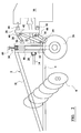
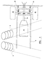
- the linkage arrangement as shown in Figure 2 comprise three link members 30, 32, 34 pivotally connected at first ends thereof to a upstanding rear section 36 of the frame.
- the other ends of the link members are pivotally connected to a back plate 38 at respective fixed pivot mounts 40, 42, 44.
- the back plate 38 has suitable mounting means 46, such as a pin and socket arrangement, for mounting the auxiliary device 16 to the back plate.
- Such a linkage arrangement 22 is provided at each lateral side of the harrow so that three link members are connected to each side of the back plate 38; as shown in Figure 3.
- the rear frame section 36 supports lifting mechanisms 48, typically two; one on each side of the frame.
- the lifting mechanism may have any suitable form but preferably comprises a first hydraulic lift which can lift the disc harrows at the rear and the auxiliary device 16, or lower the disc harrows and auxiliary device 16. In use, this would be done at the end of every pass and for road travel.
- the two upper and lower link members 30, 34 are solid members and the central link members are second hydraulic lift members.
- the upper, central and lower pivot connections 50, 52, 54 are fixed to the frame section 36.
- the hydraulic lift mechanisms 32 When attaching an auxiliary device 16 to the back plate 38, the hydraulic lift mechanisms 32 are operated to raise and lower the pivot connections 40, 44 of the back plate thereby causing the link members 30, 34 to pivot.
- a linkage arrangement comprises lift mechanisms 48 as described with reference to Figure 2 and upper and lower link members similar to those described with reference to Figure 2. However, in this embodiment the hydraulic lift members 32 and the back plate 38 are omitted. The remote ends of the upper and lower link members are adapted to be connected directly to the auxiliary device 16. The operation is similar to that described with reference to Figure 2 in so far as the lift mechanisms 48 are operable to raise the frame 2 and pivot connections 50, 52, 54 thereby raising the auxiliary device 16.
- a 30 gallon fuel tank and a 4 cylinder, 70-80 horse power engine may be used.
- a ballast or a seed tank 13 with cross auger may be provided on the frame in front of the fuel tank.
- the wheel pair and axle 28 typically has sufficient strength to support the disc harrow and an auxiliary device such as a power harrow and drill.
- a container for grain or fertiliser, such as a 1 ton hopper, may be mounted at the front of the harrow.
- the harrow of the invention supports heavy duty cultivator discs 6, 8.
- a front section of the frame 2 comprises connected upper and lower sections 60 and 62 respectively.
- the upper and lower sections 60 and 62 are connected by a pivotable link 64 and by an extendible hydraulic lift 66.
- An upper end of the hydraulic lift is secured to a pivotable brace 68 held on a support 70 which is fixed to the upper section 60.
- a lower end of the hydraulic lift 66 is secured to the lower section 62.
- a depth control screw 70 is located on the upper section 60, and has the same operation as the depth control 48 described above.
- a harrow of the invention can be attached to a tractor for use as a disc harrow and can be used alone or in combination with an auxiliary device such as a drill, sub-soiler, tine cultivator, fertiliser spreader or the like, the latter being easily dismountable and interchangeable. Since the harrow of the invention can be used with conventional auxiliary devices without adaptation, these can continue to be used directly with a tractor where required so that the harrow of the invention gives the farmer greater versatility. This is particularly advantageous for any farmer large or small.
Landscapes
- Life Sciences & Earth Sciences (AREA)
- Engineering & Computer Science (AREA)
- Mechanical Engineering (AREA)
- Soil Sciences (AREA)
- Environmental Sciences (AREA)
- Zoology (AREA)
- Soil Working Implements (AREA)
- Agricultural Machines (AREA)
Applications Claiming Priority (2)
| Application Number | Priority Date | Filing Date | Title |
|---|---|---|---|
| GB9913621 | 1999-06-12 | ||
| GB9913621A GB2350996B (en) | 1999-06-12 | 1999-06-12 | Agricultural machine |
Publications (2)
| Publication Number | Publication Date |
|---|---|
| EP1064831A2 true EP1064831A2 (fr) | 2001-01-03 |
| EP1064831A3 EP1064831A3 (fr) | 2002-09-11 |
Family
ID=10855172
Family Applications (1)
| Application Number | Title | Priority Date | Filing Date |
|---|---|---|---|
| EP00304805A Withdrawn EP1064831A3 (fr) | 1999-06-12 | 2000-06-06 | Machine agricole |
Country Status (2)
| Country | Link |
|---|---|
| EP (1) | EP1064831A3 (fr) |
| GB (1) | GB2350996B (fr) |
Families Citing this family (1)
| Publication number | Priority date | Publication date | Assignee | Title |
|---|---|---|---|---|
| CN104584723B (zh) * | 2015-01-07 | 2016-04-06 | 山东理工大学 | 一种金银花冬季培土施肥机 |
Family Cites Families (9)
| Publication number | Priority date | Publication date | Assignee | Title |
|---|---|---|---|---|
| US1890621A (en) * | 1932-06-22 | 1932-12-13 | George A Newhouse | Cultivating implement |
| US2588561A (en) * | 1949-08-29 | 1952-03-11 | Fred W Opp | Apparatus for electrically treating the soil |
| NL8204382A (nl) * | 1982-09-29 | 1984-04-16 | Lely Nv C Van Der | Grondbewerkingsmachine. |
| FR2549340A1 (fr) * | 1983-07-19 | 1985-01-25 | Amazonen Werke Dreyer H | Combinaison fermee d'instruments agricoles tels qu'un outil de travail du sol et un semoir |
| NL191227C (nl) * | 1983-10-03 | 1995-04-03 | Lely Nv C Van Der | Grondbewerkingsmachine. |
| DE9312364U1 (de) * | 1993-08-25 | 1993-10-28 | Rabewerk Gmbh + Co, 49152 Bad Essen | Bodenbearbeitungskombination |
| WO1995015074A1 (fr) * | 1993-12-01 | 1995-06-08 | Martin Niebler | Machine de labourage de sol |
| IT1278028B1 (it) * | 1995-02-23 | 1997-11-17 | Ind Meccanica F Lli Tortella S | Macchina agricola combinata che compie, in un solo passaggio l'intera gamma di operazioni per la seminagione. |
| DE19705958A1 (de) * | 1997-02-17 | 1998-08-20 | Amazonen Werke Dreyer H | Landwirtschaftliche Bestellkombination |
-
1999
- 1999-06-12 GB GB9913621A patent/GB2350996B/en not_active Expired - Fee Related
-
2000
- 2000-06-06 EP EP00304805A patent/EP1064831A3/fr not_active Withdrawn
Non-Patent Citations (1)
| Title |
|---|
| None |
Also Published As
| Publication number | Publication date |
|---|---|
| GB2350996B (en) | 2003-08-20 |
| GB9913621D0 (en) | 1999-08-11 |
| GB2350996A (en) | 2000-12-20 |
| EP1064831A3 (fr) | 2002-09-11 |
Similar Documents
| Publication | Publication Date | Title |
|---|---|---|
| US4241674A (en) | Sub-soil planter | |
| US5431232A (en) | Quick change mounted packer system | |
| CN101119633B (zh) | 组合农业机器 | |
| US4048929A (en) | Combined apparatus for tilling and planting | |
| US8826836B2 (en) | Row treating unit for agriculture implement | |
| AU2004226690B2 (en) | Improved seed drill | |
| US3367293A (en) | Landscaping implement | |
| DK2051576T4 (en) | IMPROVED SEED MACHINE | |
| US3528507A (en) | Field tillage apparatus | |
| US3335681A (en) | Agricultural tillage unit | |
| US3866552A (en) | Roto sod seeder | |
| JP7473999B1 (ja) | 耕うん同時畝立て播種機及び耕うん同時畝立て播種方法 | |
| US6843186B2 (en) | Narrow row spacing planter | |
| EP0337533A2 (fr) | Engin à moteur de culture de la terre | |
| US2221769A (en) | Tractor attachment | |
| EP1064831A2 (fr) | Machine agricole | |
| CA1237014A (fr) | Chassis articule de machine agricole | |
| EP4346367B1 (fr) | Semoir pour cultivateur | |
| US2563185A (en) | Tractor implement attachment | |
| GB2400296A (en) | Soil cultivator and seed drill | |
| US2347017A (en) | Rotary soil tiller | |
| AU2012200618B2 (en) | Improved Seed Drill | |
| CN2376707Y (zh) | 通架式松耘耕播机 | |
| CN108464088A (zh) | 一种深度调节播种施肥机 | |
| US11083123B2 (en) | Multi-purpose agricultural implement |
Legal Events
| Date | Code | Title | Description |
|---|---|---|---|
| PUAI | Public reference made under article 153(3) epc to a published international application that has entered the european phase |
Free format text: ORIGINAL CODE: 0009012 |
|
| AK | Designated contracting states |
Kind code of ref document: A2 Designated state(s): AT BE CH CY DE DK ES FI FR GB GR IE IT LI LU MC NL PT SE |
|
| AX | Request for extension of the european patent |
Free format text: AL;LT;LV;MK;RO;SI |
|
| RIN1 | Information on inventor provided before grant (corrected) |
Inventor name: GREEN, CHRIS |
|
| PUAL | Search report despatched |
Free format text: ORIGINAL CODE: 0009013 |
|
| AK | Designated contracting states |
Kind code of ref document: A3 Designated state(s): AT BE CH CY DE DK ES FI FR GB GR IE IT LI LU MC NL PT SE |
|
| AX | Request for extension of the european patent |
Free format text: AL;LT;LV;MK;RO;SI |
|
| RIC1 | Information provided on ipc code assigned before grant |
Free format text: 7A 01B 25/00 A, 7A 01B 21/04 B, 7A 01B 49/06 B, 7A 01B 19/00 B, 7A 01B 21/08 B, 7A 01B 51/04 B, 7A 01B 49/02 B |
|
| AKX | Designation fees paid | ||
| REG | Reference to a national code |
Ref country code: DE Ref legal event code: 8566 |
|
| STAA | Information on the status of an ep patent application or granted ep patent |
Free format text: STATUS: THE APPLICATION IS DEEMED TO BE WITHDRAWN |
|
| 18D | Application deemed to be withdrawn |
Effective date: 20030312 |