EP1064873A2 - Wannenträger - Google Patents
Wannenträger Download PDFInfo
- Publication number
- EP1064873A2 EP1064873A2 EP00113668A EP00113668A EP1064873A2 EP 1064873 A2 EP1064873 A2 EP 1064873A2 EP 00113668 A EP00113668 A EP 00113668A EP 00113668 A EP00113668 A EP 00113668A EP 1064873 A2 EP1064873 A2 EP 1064873A2
- Authority
- EP
- European Patent Office
- Prior art keywords
- support
- tub
- foam
- tub support
- floor
- Prior art date
- Legal status (The legal status is an assumption and is not a legal conclusion. Google has not performed a legal analysis and makes no representation as to the accuracy of the status listed.)
- Withdrawn
Links
Images






Classifications
-
- A—HUMAN NECESSITIES
- A47—FURNITURE; DOMESTIC ARTICLES OR APPLIANCES; COFFEE MILLS; SPICE MILLS; SUCTION CLEANERS IN GENERAL
- A47K—SANITARY EQUIPMENT; ACCESSORIES THEREFOR, e.g. TOILET ACCESSORIES
- A47K3/00—Baths; Showers; Appurtenances therefor
- A47K3/28—Showers or bathing douches
- A47K3/40—Pans or trays
-
- A—HUMAN NECESSITIES
- A47—FURNITURE; DOMESTIC ARTICLES OR APPLIANCES; COFFEE MILLS; SPICE MILLS; SUCTION CLEANERS IN GENERAL
- A47K—SANITARY EQUIPMENT; ACCESSORIES THEREFOR, e.g. TOILET ACCESSORIES
- A47K3/00—Baths; Showers; Appurtenances therefor
- A47K3/16—Devices for fastening baths to floors or walls; Adjustable bath feet ; Lining panels or attachments therefor
- A47K3/1605—Hard foam bathtub supports
Definitions
- the invention relates to a tub support a foam such as mineral, inorganic, organic lightweight foam, especially particle foam such as EPP, EPS, e.g. shower tray support or bathtub support, with a circumferential, a support wall for a tub support frame that forms an external tiling, where the tub support floor as a shelf is formed by filling in the tub support frame trained receiving opening.
- a foam such as mineral, inorganic, organic lightweight foam, especially particle foam such as EPP, EPS, e.g. shower tray support or bathtub support, with a circumferential, a support wall for a tub support frame that forms an external tiling, where the tub support floor as a shelf is formed by filling in the tub support frame trained receiving opening.
- a tub support made of polystyrene Art is known from DE-PS 38 38 753.
- the tub support floor has peripheral protrusions on that in matching recesses of the tub support frame can be inserted to connect the two parts.
- Of the Underside of the tub support floor go molded Support from. They can be broken down over predetermined height levels to the desired or required carrying height set up.
- tub supports into which the tubs are placed be used in a form-fitting manner; but here too due to the tub support, especially in the floor area full support of the tub floor is given.
- the present Invention set the task of a generic Trough support with improved support train more stable use. This is supposed to quite thin tubs like acrylic tubs in particular problem of a dellung, as in local maximum loads can occur, also risk of breakage the tub in case of deflection, with simple means be overcome.
- the task is first and foremost with one Tub support with the features of claim 1 solved, it is based on the fact that between the tub support frame and the tub support floor is a partially filled one Dodge space is formed, in which displaced Local foam is added.
- foam swelling rigid foams are understood here, the can support or casting compounds, possibly with Filled with light materials, be it on the application Construction site or already at the manufacturer.
- the invention also applies to a tub support a foam such as mineral, inorganic, organic lightweight foam, especially particle foam such as EPP, EPS, for example shower tray supports or bathtub support with a surrounding, a support wall for external tiling Tub support wall, possibly designed as a tub support frame and a tub support floor to accommodate displaced arrest agent in proposal that the of accessible from above the tub support floor a fissure structure has a variety of between support formations leaving valley-like alternative spaces.
- the variety of support formations results in one rich, self-balancing support against the tub shape.
- the arrest mass doesn't just work connecting and reinforcing at the same time, but also compensating for tolerance deviations, whereby the superfluous part in the valley-like alternative areas is pushed. In this way, it still arises an amination grid, so that even particularly brittle set acrylic materials with regard to Dynamic movements no longer occur are critical. Rather, it is an excellent one Long-term behavior.
- the tub support floor and / or the tub support has recesses on the inside or have to absorb local foam. That results, so to speak an interlocking joint. Also be here Excess portions of the foam or potting compound unhindered in the inside recesses added. The proportion of the tub shape Local foam or potting compound is thus increased. To a Strain or lift the, as I said, as a lid can rule out functioning tray support floor this is held down by suitable means such as weights become. Another means is, for example, use a hold-down device of a corresponding device. Leaving the space between the the tub support frame can be connected and / or the inside of the tub support base is also smooth be trained.
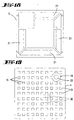
- tub support floor act as a foothold of the alternative space a solution in that the tub support floor is advantageous through openings in a grid-like configuration having. So here is the full breadth of the tub support floor for the local foam or Potting compound used.
- the tub support frame inside a stop step trains for the tub support floor. It is supported depend on it and is thus correctly defined.
- the said stop level can be a bar act, preferably integrally molded, or also through a recess creating a step fold.
- the invention proposes that the tub support floor as an intermediate floor above a Tub support base is arranged.
- the related one Tub support base is discussed in DE-OS 198 47 911, also in connection with the function a tub support supplement with associated Tub shape.
- the intermediate floor acts here as with the tub support frame connected or connectable box bottom, a lost formwork, as it were. So far The intermediate floor then takes over the reservoir function here for the excess mass.
- the tub support is the tub support supplement.
- the foam injection openings are comparatively small, such that they are in terms of Local foam injected through other openings offer certain flow resistance to leakage.
- the invention also features a tub support inserted tub shape, the tub support made of Foam such as mineral, inorganic, organic Light foam, especially particle foam such as EPP, EPS, for example as a shower tray support or Bathtub support formed with a circumferential, a support wall for external tiling forming tub support frame and tub support floor, in Propose that the bottom of the tub form for support using local foam or one if necessary at the same time reinforcing adhesive layer immediately with a large area is glued to the tub support floor. It also points here the tray support base in a grid-like design Through openings. It also turns out advantageous that the tub support frame inside a stop step forms for the tub support floor. In addition, it is favorable that the tub support floor as Intermediate floor formed above the tub support base is.
- Foam such as mineral, inorganic, organic Light foam, especially particle foam such as EPP, EPS
- EPS for example as a shower tray support or Bathtub support formed with a circumferential, a support wall for external tiling forming
- the adhesive layer is preferably one with less or hardly existing flow tendency Mass, in particular based on PU, which is hardenable. A correspondingly gelatinous, hardly flowable Mass is not so easy when applied.
- the Reinforcement provides good power distribution and bonding the tub shape. It is also provided that the Trough-shaped bottom on its underside on the side of the tub support has at least partially a reinforcement. Latter is preferably limited to the area of the drain opening the shower tray or bathtub and is used for Support of the assembly opening area. It is also provided that the reinforcement in the area of a large opening, for example an assembly opening of the tub base, is trained.
- foam such as mineral, inorganic, organic lightweight foam, in particular Particle foam such as EPP, EPS, e.g. shower tray support or bath support, with a bath support floor and a circumferential, a support wall for tub support frame
- the procedure is then provided that the trough bottom before applying the Ortschaums or the adhesive layer at least partially is provided with reinforcement.
- the latter can by the local foam or the like at least one more Experience edge embedding.
- the tub support floor under Leave or form a foam filled Gap between the trough base and the trough base is used. Then the tub support is marked by a trained on the tub support floor all-round web to delimit a local foam receiving room with a view to creating yourself up to the trough shaped floor extending free space.
- the footbridge forms a wall that cannot be crossed for the distributing, finally hardening mass.
- tub support made of a foam like mineral, inorganic, organic lightweight foam, in particular particle foam such as EPP, EPS formed is, for example, shower tray support or bathtub support, in the fact that the tub shape, if necessary partially or fully reinforced, with a curable embedding compound, if necessary under simultaneous reinforcement of the tub shape using the Embedding compound, is coated and the so coated Tub shape is inserted into a tub support.
- foam like mineral, inorganic, organic lightweight foam, in particular particle foam such as EPP, EPS formed is, for example, shower tray support or bathtub support, in the fact that the tub shape, if necessary partially or fully reinforced, with a curable embedding compound, if necessary under simultaneous reinforcement of the tub shape using the Embedding compound, is coated and the so coated Tub shape is inserted into a tub support.
- the so coated Tub shape is inserted into a tub support frame and a tub support floor with displacement of investment material in an escape room in the tub support is inserted.
- the shelf can also be shaped (web system), that the emerging ensemble directly as a carrier can be assembled with tub at the manufacturer.
- the support formations on the front Form plateaus are relatively minor Stand height and provide a stable base overall.
- the table mountain-like support shape is further designed so that they have a circumferential overflow ditch on the foot side having. Given the multitude of Support formings in the form of plateaus to form a whole Trench system. An abundance that on the surrounding slope of the plateau does not find enough space Flow overflow ditch of the neighboring plateau connected. It is also proposed that the end faces of the support formations at least partially Recreate the outer contour of the tub shape. That makes a good nestling with balanced support. About this it is provided that the inner surface of the Trough support wall has wall support formations. So the fissure structure also sets in this area continues.
- the tub shape is a wall support formed as a support rib aligned on the vertical.
- the field can be interrupted like the support formations on the tub support floor.
- the support rib is graded. This applies preferably to all wall support shapes.
- an acrylic tub shape in a molding tub support (Material preferably used as stated above) in that the acrylic tub shape first with a Potting compound contributing to the reinforcement of the acrylic tub shape is at least partially covered and in the course inserting the acrylic tub shape into the tub support this potting compound also for arrest with the tub support is used.
- the application can be by spraying happen.
- the the tub support is turned down accordingly then put on like a hat. It comes to the explained displacement that provides an optimal support the sealing compound, as far as its excess material is concerned.
- the tub support designed in the form of a shower tray support 1 takes a shower tray 2. It is preferred made of acrylic. It can also be another material such as steel, ABS, quaryl. It can also a multilayer plastic tub.
- the tub support 1 consists of a tub support frame 3.
- a tub support base 4 is assigned to this. It deals around a shelf. The latter is located itself in a receiving opening 5 of the so assembled Tub support 1.
- the assignment of the under fill the receiving opening 5 inserted tray support floor 4 is defined.
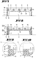
- the inside of the Tub support frame 3 takes into account a stop level 6. It is a horizontal flank of one integrally molded on all four legs of the tub support frame 3 trims. The latter can also as a wall jump up to the upper edge of the forehead 7 of the tub support 1 (see FIG. 20). Self a one-piece construction of parts 3 and 4 can grip (see Fig. 11).
- Production material of the tub support 1, the parts 3 and 4 so, is particle foam like EPP, EPS.
- the all-round, coherent tub support frame 3 provides the support wall with its vertical outside for example, plastering or tiling the im Floor plan of a square tub support 1.
- plastering or tiling the im Floor plan of a square tub support 1.
- sanitary Visible surfaces it is on the DE-Gm 295 09 901.
- the tub support base 4 has recesses 8. The are facing a tub support cavity 9. Latter exists between the outer contour of the shower tray 2 and the space-retaining inside of the tub support 1.
- the Tub support cavity 9 provides the filling space for one Potting compound or foam, preferably curing local foam.
- the filling space, formed by the tub support cavity 9, is not just a filling room, but also an alternative room for the local foam or the potting compound.
- the when the unit is closed those who are looking for the way, i.e. displaced Local foam migrates in the one that points outwards in FIG. 22 Edge space between the outer flank of the shower tray and inner wall of the tub support frame 3.
- the escape room bears the reference number 9 '. As can be seen, not completely filled in, so that a soffit pressure avoiding migration of the substance is not impeded is. An empty section is shown.
- the wall-forming backfill 10 is the Back 11 of the tub support 1 built up.
- the shower tray 2 is previously in the tub support frame 3 mounted. This happens under his control outwardly angled edge 12 over the front edge 7 of the tub support 1. At this point there is a bond instead of.
- the adhesive layer bears the reference symbol 13. There is an additional function of the adhesive layer 13 in that they are there between shower tray 2 and Seals support 1. The edge 12 is again at the end angled.
- the tub support base 4 smooth on the inside. For a thickness sufficient layer formation from the rear side 11 here is taken care of.
- Fig. 23 provides for the same basic principle that excess Filling 10 on the side of the tub support floor 4 is received in recesses 8.
- the shower tray is placed on the face Tub support 1 backfilled with respect to the shower tray 2.
- the one generously applied to the back of the shower tray 2 Local foam gets into the wedge space inside the frame the tub support cavity 9 as well as in the area of the tub support floor 4. At least before used like a lid for curing. Excess Local foam migrates into the recesses 8 on the inside the tub support base 4 and, if necessary, in corresponding recesses on the inside of the tub support frame 3 (The latter are not shown in the drawing).
- the lid is forming Tub support base 4 closed to the outside.
- the excess part can cover the entire vertical depth, i.e. the thickness of the tray support floor 4 can be used.
- the well distributed Recesses 8 extend over the entire Thickness of the same.
- the tub support base 4 in a lattice-like design of the tub support base 4 window-like through openings.
- the tub support base 4 can Need to be held down.
- the one in the outward direction Foaming jerk going into the passage opening outgoing material cakes are created, labeled with 14. They are interconnected and act like bridge-like beams of the stable created in this way Total wearing course.
- the tub support 1 is already ready for use. He points the usual laying shafts 17. these can in the direction of, for example, the raw floor 18 of a building to be bottomless.
- the diagonally and parallel to the side wall running laying shafts 17 meet in the Area of an opening 19 of the tub support 1, realized as a breakthrough in the lid of the tub support base 4.
- the drain hole 20 of the shower tray 2 is positioned.
- FIG. 17 An integrally formed tub support 1 with a Tub support base 4 and a tray support frame 3 the particle foam mentioned is then identified through the tub support base 4 and / or the tub support frame assertive, if necessary additionally Local foam injection openings designed for assembly openings 15.
- FIG. 17 These foam injections 15 are comparative small in size. There is a much finer lattice structure in front. The dimensioning is such that in Regarding local foam injected through other openings a certain flow resistance Provide tiles of excess local foam. The injection but can also practice self-piercing cannulas become.
- the foam injection openings 15 protrude through the cover, i.e. of the tub support floor 4, in the tub support cavity 9.
- tub support floor 4 as an intermediate floor is arranged above a tub support base S.
- the tub support base S contains partial laying shafts 21. He (S) can be plug-assigned to the tub support 1 via a step fold 22.
- the inside of the acting as a mounting plate tub support base S directly to the outside of the tub support base 4 on.
- the installation of the tub support 1 with it recorded tub shape happens so that the first Tub support base S is attached to the raw floor 18 and that subsequently one with a tub support base S to complement a tub support 1 Tub support supplement piece connected tub shape the tub support base is placed.
- the trough support 1 thus forms that Supplement for tub support.
- a base S can be provided with a drain positioning aid.
- the tub support 1 with the tub shape inserted is done so that the bottom 23 of the tub shape for support by means of the local foam or alternatively an adhesive layer 24 over a large area and firmly with glued to the tub support floor 4.
- the adhesive layer 24 (see Fig. 21) is a PU mass.
- the trough base 23 is on at least partially of its underside on the tub support side provided with a reinforcement 25.
- This one Reinforcement with multiple layers results in stiffening in zones with a smaller support surface, e.g. in Area of the relatively large opening 19, for example one Assembly opening of the tub support base 4.
- the edge 12 of the tub support 1 facing away collar 26 from a corresponding going beyond the thickness of the tub support base 4 Section of the four legs of the tub support frame 3 is formed.
- the plug collar 26 fits snugly the stepped peripheral edge recess of the tub support base S a, so in the step fold 22.
- the remaining one Visible edge of the tub support base S and the skirt-forming Support wall for the external tiling are aligned vertically.
- FIGS. 22 and 23 of the invention have the same reference symbols as the basic version, without repeated text.
- the adhesive layer 24 can act as an adhesion promoter act as the local foam, i.e. from the backfill 10 be overlaid.
- a tuck-collar-free solution can also be implemented (see Figs. 13 and 15).
- the docking materials for this will be explained further below.
- the procedural steps to create the support of the Trough shape in the tub support 1 are further such that the tub shape on the underside, in particular on the bottom, is largely covered with foam and that subsequently with partial displacement of the local foam in overflow areas of the box-like tub support 1 is put on.
- the positioning can be done immediately the reinforcement.
- the excess, at the tub-hardening mass gets into the recess 8.
- reinforcement and gluing in one step. It also results accordingly Arming and supporting the tub 2 in one step.
- This wall-like web 28 serves to limit a corresponding Location foam room with regard to the Creation of an extending to the trough bottom 23 Free space 29.
- the free space 29 can in particular be bigger with a bathtub.
- Process engineering can be used to support a tub shape in the tub support 1 are also proceeded that after inserting the tub shape into the tub support 1 by in the tub support - if necessary, additional to an assembly opening - trained injection openings Local foam in the gap 27 between the trough base 23 and the tub support base 4 is injected for large-area support of the tub shape in the Tub support 1.
- the adhesive layer 13 needs not to provide the need for sealing. The displaced air can escape there.
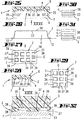
- a corresponding Tub support 1 made of a foam such as mineral, inorganic, organic lightweight foam, in particular Particle foam such as EPP, EPS, for example shower tray supports or bathtub support, with a circumferential, a support wall for external tiling forming tub support wall 35, optionally configured as tub support frame 3, and a tub support floor 4 for taking up displaced arrestants like this proceeded that the tub support floor accessible from above 4 has a fissuring structure Z with a variety of valley-like alternative spaces 36 leaving support formations 37.
- the support formations 37 are plateaus with the Complete the end faces forming the supporting surface.
- the Support formations 37 run in series and cross and across. They also cover the tub support floor 4 like the rising inner surface of the tub support wall 35.
- the wall support formations are designated 37 '. Outside, the tub support base 4 can be made in one piece Structure is ribbed instead of smooth as shown, forming Cut-outs for siphon and lines.
- the plateaus, i.e. H. Support formations 37 have one truncated pyramid shape.
- the corresponding one Floor plan is shown in FIGS. 27 and 29. It can but other geometric shapes can also be provided, such as having circular diameters Studs or pillar stumps.
- escape spaces 36 form in association with adjacent support formations 37 the Fissuring structure Z on the foot side of the formations 37 onset of overflow ditches Ü.
- the latter are hiring regular trench system, so different Material accumulations can be managed with avoidance are.
- stepped support rib is slightly out Fig. 25 can be seen.
- the step joints run essentially in the vertical.
- the tub support 1 is otherwise both redesignable with regard to the assignment of what was described above, plug-in tub support base S, with regard to the laying shafts discussed in detail 17, 21, the opening 19 for the connection hole and finally also with regard to the recesses 8 described, which also directly on the back of the tub support 1, like set out above, can be molded. These details should not be repeated here, but rather, it is said to be based on a special procedure be pointed out.
- This installation procedure an acrylic tub shape F in a foam tub support 1 provides that: the acrylic bath form F initially with one for reinforcement the potting compound 38 which contributes to the acrylic tub shape F. completely, at least partially, is covered and in By inserting the acrylic tub shape F into the tub support 1 this potting compound 38 also for arrest is used with the tub support 1.
- the corresponding one Application of the potting compound 38 on the back of the Acrylic tub shape F is expediently done by spraying.
- the potting compound 38 extends into the edge 12 (see Fig. 27), which is so well armored. When entering there are no kinks. As found, it is enough already a thin order. It can be 5 mm. Depending on the roughness of the tub support 1 is recommended an order of approx. 10 mm.
- the hardening casting compound provides a highly stable reinforcement, so that mostly quite brittle acrylic workpiece, even with above average ones dynamic movements are no longer at risk of breakage is. The long-term behavior in this direction is remarkable.
- Fig. 30 shows the layer a designated 38 Sealing compound.
- Figure 31 illustrates a three layer Construction. They are used differently discontinued polyurethanes, which are also in the rest can be applied economically.
- the corresponding Multi-component system is preferred for strengthening of deep drawing parts for sanitary articles.
- the two to one three-component, highly filled reinforcement system can be applied solvent-free. It can be Make the setting so that it falls on sloping surfaces there is good liability.
- the setting can be in Optimally adjusted in relation to the production time, that such materials will soon be tack-free and easy to edit. Added to this was the advantage the light weight. With multi-layer application is worked wet on wet so that it is at the interfaces there is a quick reaction.
- a Potting compound 38 is a solid hard layer is.
- the second layer b is followed by a more foam-like one Soft layer on casting compound 38 and finally again a layer labeled c as a solid hard layer.
- this has distance and on the other cushioning effect in the so-called neutral Fiber.
- the layer a closer to the tub shape F is shown Stress under a certain compression effect.
- the peripheral Layer c of the sandwich-like structure stands under train. The forces are well absorbed in the field more foam-like hardening layer b acts with only two layers (a, b) filling the space in Reference to the recesses 8 and the tub support cavity 9.
- the end faces of the exposed support formations 37 can have a dent 39. That is in Fig. 32 in dash-dotted line style shown.
- the ones there penetrating mass acts as a locking member with respect parallel displacements of the connected parts 1, 2 or F.
- one of the Claims 1 to 4 of this application may be of importance can, is, a tub support, in which in a combination of tub support 1 and tub support base S the Tub support 1 forms the tub support supplement.
- one of the Claims 1 to 5 of this application may be of importance can, is, a tub support, in which the tub bottom 23 on its underside on the tub support side at least partially has a reinforcement 25.
- one of the Claims 1 to 5 of this application may be of importance can, is, a tub support, in which the reinforcement 25 in the area of a large opening 19, for example one Installation opening of the tub support base 4 is formed.
- the invention also relates to a method which alone or in combination with claim 6 of importance is to support a tub shape in one Tub support, in which the trough base 23 in front Applying the local foam or the adhesive layer at least is partially provided with a reinforcement 25.
- the invention also relates to a method which alone or in combination with claim 6 of importance is to support a tub shape in one Tub support, in which the tub support base 4 under Formation of a foam-filled gap 27 between Pan-shaped shelf 23 and tray support base 4 are used becomes.
- a tub support in which on the tub support floor 4 a circumferential web 28 is formed for delimiting a local foam intake room with a view on the creation of a down to the tub mold floor 23 extending space 29.
- Subject of the invention also alone or in combination with one of the claims, in particular one of the Claims 1 to 5 and 9 of this application, of importance can be, a tub support, in which one Support formation 37 on the foot side starting with a circumferential one Overflow trench Ü has.
- Subject of the invention also alone or in combination with one of the claims, in particular one of the Claims 1 to 5 and 9 of this application, of importance can be, a tub support, in which the End faces of the support formations 37 at least partially recreate the outer contour of the tub shape F.
- Subject of the invention also alone or in combination with one of the claims, in particular one of the Claims 1 to 5 and 9 of this application, of importance can be, a tub support, in which the Inner surface of the tub support wall 35 wall support formations 37 '.
- Subject of the invention also alone or in combination with one of the claims, in particular one of the Claims 1 to 5 and 9 of this application, of importance can be, a tub support, in which the Wall support formation 37 'than on the vertical aligned support rib is formed.
- Subject of the invention also alone or in combination with one of the claims, in particular one of the Claims 1 to 5 and 9 of this application, of importance can be, a tub support, in which the Support rib is stepped.
- the invention also relates to a method which alone or in combination with claim 6, 7, 8 and 10 is important for supporting a tub shape in a tub support, in which the casting compound 38 multilayer a, b, c is applied.
Landscapes
- Health & Medical Sciences (AREA)
- Public Health (AREA)
- Epidemiology (AREA)
- General Health & Medical Sciences (AREA)
- Floor Finish (AREA)
- Cosmetics (AREA)
- Devices For Medical Bathing And Washing (AREA)
- Bathtubs, Showers, And Their Attachments (AREA)
Abstract
Description
- Fig. 1
- eine Duschwanne in Perspektive;
- Fig. 2
- die Draufsicht hierzu;
- Fig. 3
- den Schnitt gemäß Linie III-III in Fig. 2;
- Fig. 4
- die Draufsicht auf den isoliert dargestellten Wannenträgerboden;
- Fig. 5
- den Schnitt gemäß Linie V-V in Fig. 4;
- Fig. 6
- die zu einer Duschwanne zusammenfügbaren Teile im Schnitt wie Fig. 3, und zwar in Explosionsdarstellung;
- Fig. 7
- in Schnittdarstellung diese Teile in zusammengefügtem Zustand, verfüllbereit;
- Fig. 8
- die Situation nach dem Verfüllen; das Verfüllen ist selbstredend vor Aufsetzen des Einlegebodens, d.h. bspw. des Wannenträgerbodens, möglich;
- Fig. 9
- eine Herausvergrößerung IX-IX der Fig. 8, jedoch in einer Abwandlung dahingehend, daß Wannenträgerrahmen und Wannenträgerboden einstückig ausgebildet sind, wobei der Wannenträgerrahmen einen Steckkragen im Sinne eines Stufenfalzes aufweist;
- Fig. 10
- eine Herausvergrößerung wie Fig. 9, und zwar mit steckkragenfreiem Abschluß;
- Fig. 11
- eine der Fig. 10 entsprechende Darstellung, als Audockmittel einen Paßstift aufweisend, der in eine Bohrung des Wannenträgersockels einführbar ist;
- Fig. 12
- den Wannenträgersockel in Unteransicht, eine reiche Verrippung zeigend;
- Fig. 13
- den Wannenträger als kastenbildendes Element, bei dem der Wannenträgerboden in dem Wannenträgerrahmen anschlagdefiniert eingesetzt ist, und zwar in Schnittdarstellung;
- Fig. 14
- eine gleiche Schnittdarstellung, einen Wannenträger zeigend, der bezüglich der Dicke des Wannenträgerbodens und der entsprechend verlängerten Wandung des Wannenträgerrahmens zu einem Aufstellgerippe verlängert ist, dies mit Ausbildung vertikal vergrößerter Verlegeschächte für die Rohrleitung;
- Fig. 15
- den Wannenträger in perspektivischer Darstellung, und zwar gegen die Unterseite gesehen;
- Fig. 16
- die Ausbildung einer Wannenform im Querschnitt mit gegenüber Fig. 15 wesentlich querschnittsverringerten Ausnehmungen, Injektionsöffnungen bildend;
- Fig. 17
- einen Schnittauszug, eine reiche Säulenausbildung wiedergebend nebst Spalt zur Aufnahme der die Duschwanne abstützenden Verfüllung;
- Fig. 18
- den Wannenträgersockel in Draufsicht, die anteiligen Verlegeschächte dieses Elements verdeutlichend;
- Fig. 19
- die Unteransicht gegen die Einheit Wannenträgerboden/Wannenträgerrahmen;
- Fig. 20
- einen Schnittauszug des Wannenträgers mit dem freigespannten Bereich des Abflußloches zugeordneter Armierung;
- Fig. 21
- einen Schnitt durch eine Duschwanne mit rückseitig aufgetragener Kleberschicht;
- Fig. 22
- einen Schnitt wie Fig. 3, eine Abwandlung der Duschwanne zeigend dergestalt, daß der Wannenträgerboden innenseitig glattflächig ausgebildet ist und integral mit dem Wannenträgersockel ist;
- Fig. 23
- einen entsprechenden Querschnitt, jedoch innenseitig mit Ausnehmungen versehen;
- Fig. 24
- eine Herausvergrößerung XXIV-XXIV in Fig. 23;
- Fig. 25
- einen in Stülpstellung gebrachten Wannenträger, aufweisend eine dem Prinzip nach der Zerklüftungsstruktur gemäß Fig. 17 nahe kommenden Variante des Wannenträgers;
- Fig. 26
- die zugehörige Acryl-Wannenform, mit dem Gesicht nach unten weisend sowie mit rückenseitig aufgetragener Vergußmasse;
- Fig. 27
- eine Ansicht in den Wannenträger gemäß Pfeil XXVII in Fig. 25;
- Fig. 28
- eine bezüglich der Zerklüftungsstruktur bestehende Spezifikation in Form durchgehender Stützrippen als Wandungs -Stützausformungen;
- Fig. 29
- eine Ansicht in Richtung des Pfeiles XXIX in Fig. 28;
- Fig. 30
- eine Herausvergrößerung einer Partie der Acryl-Wannenform, zeigend einen einschichtigen Auftrag an Vergußmasse;
- Fig. 31
- dasselbe, veranschaulichend einen dreischichtigen Auftrag an Vergußmasse;
- Fig. 32
- eine Herausvergrößerung im Grenzbereich der miteinander verbundenen Teile Acryl -Wannenform und Wannenträger.
Claims (10)
- Wannenträger (1) aus einem Schaumstoff wie mineralischem, anorganischem, organischem Leichtschaum, insbesondere Partikelschaumstoff wie EPP, EPS, bspw. Duschwannenträger oder Badewannenträger, mit einem umlaufenden, eine Trägerwandung für eine außenseitige Verfliesung bildenden Wannenträgerrahmen (3), wobei der Wannenträgerboden (4) als Einlegeboden ausgebildet ist, unter Ausfüllen der von dem Wannenträgerrahmen (3) ausgebildeten Aufnahmeöffnung (5), dadurch gekennzeichnet, daß zwischen dem Wannenträgerrahmen (3) und dem Wannenträgerboden (4) ein teilweise gefüllter Ausweichraum ausgebildet ist, in welchem verdrängter Ortschaum aufgenommen ist.
- Wannenträger (1) aus einem Schaumstoff wie minerarlischem, anorganischem, organischem Leichtschaum, insbesondere Partikelschaumstoff wie EPP, EPS, beispielsweise Duschwannenträger oder Badewannenträger, mit einer umlaufenden, eine Trägerwandung für eine außenseitige Verfliesung bildenden Wannenträgerwandung (35) ggf. ausgestaltet als Wannenträgerrahmen (3), und einem Wannenträgerboden (4) zur Aufnahme von verdrängtem Haftungsmittel, dadurch gekennzeichnet, daß der von oben her zugängliche Wannenträgerboden (4) eine Zerklüftungsstruktur (Z) aufweist mit einer Vielzahl von zwischen sich talartige Ausweichräume (36) belassenden Stützausformungen (37).
- Integral ausgebildeter Wannenträger (1) mit einem Wannenträgerboden (4) und einem Wannenträgerrahmen (3) aus Schaumstoff wie mineralischem, anorganischem, organischem Leichtschaum, insbesondere Partikelschaumstoff wie EPP, EPS, bspw. Duschwannenträger oder Badewannenträger, wobei der umlaufende Wannenträgerrahmen (3) außenseitig eine der Verfliesung dienende Trägerwandung bildet, gekennzeichnet durch den Wannenträgerboden (4) und/oder den Wannenträgerrahmen (3) durchsetzende, gegebenenfalls zusätzlich zu Montageöffnungen ausgebildete Ortschaum-Injektionsöffnungen (15).
- Wannenträger nach einem oder mehreren der vorhergehenden Ansprüche oder insbesondere danach, dadurch gekennzeichnet, daß die Ortschaum- Injektionsöffnungen (15) vergleichsweise klein sind, derart, daß sie im Hinblick auf durch andere Öffnungen injizierten Ortschaum einen gewissen Strömungswiderstand gegenüber Ausfließen bieten.
- Wannenträger (1) mit eingesetzter Wannenform, wobei der Wannenträger (1) aus Schaumstoff wie mineralischem, anorganischem, organischem Leichtschaum, insbesondere Partikelschaumstoff wie EPP, EPS besteht, bspw. Duschwannenträger oder Badewannenträger, mit einer umlaufenden, eine Trägerwandung für eine außenseitige Verfliesung bildenden Wannenträgerrahmen (3) und Wannenträgerboden (4), dadurch gekennzeichnet, daß der Boden (23) der Wannenform zur Abstützung mittels Ortschaums oder einer gegebenenfalls zugleich armierenden Kleberschicht (24) unmittelbar großflächig mit dem Wannenträgerboden (4) verklebt ist.
- Verfahren zur Abstützung einer Wannenform in einem Wannenträger (1) aus einem Schaumstoff, bspw. mineralischem, anorganischem, organischem Leichtschaum, insbesondere Partikelschaumstoff wie EPP, EPS, bspw. Duschwannenträger oder Badewannenträger, mit einem Wannenträgerboden (4) und einem umlaufenden, eine Trägerwandung für eine außenseitige Verfliesung bildenden Wannenträgerrahmen (3), wobei der Wannenträgerboden (4) als Einlegeboden ausgebildet ist, unter Ausfüllung der von dem Wannenträger (1) ausgebildeten Aufnahmeöffnung (5) und wobei der Wannenträgerrahmen (3) stirnseitig (7) mit der Wannenform verklebt ist, dadurch gekennzeichnet, daß die Wannenform (F) unterseitig, insbesondere bodenseitig, großflächig allein oder in Kombinaton mit Ortschaum (8, 9'), Hartschaum, Vergußmasse, Klebemasse und/oder Verstärkungsmasse, überdeckt wird und daß nachfolgend unter teilweiser Verdrängung des Ortschaums in Überlaufbereiche der Wannenträgerboden (4) aufgesetzt wird.
- Verfahren zur Abstützung einer Wannenform in einem Wannenträger (1), wobei weiter der Wannenträger (1) aus einem Schaumstoff wie mineralischem, anorganischem, organischem Leichtschaum, insbesondere Partikelschaumstoff wie EPP, EPS gebildet ist, bspw. Duschwannenträger oder Badewannenträger, dadurch gekennzeichnet, daß die Wannenform, gegebenenfalls teil- oder vollarmiert, mit einer aushärtbaren Einbettungsmasse, gegebenenfalls unter gleichzeitiger Armierung der Wannenform mittels der Einbettungsmasse, beschichtet wird und die so beschichtete Wannenform in einen Wannenträger (1) eingesetzt wird.
- Verfahren nach Anspruch 20 oder insbesondere danach, dadurch gekennzeichnet, daß die so beschichtete Wannenform in einen Wannenträgerrahmen (3) eingesetzt ist und ein Wannenträgerboden (4) unter Verdrängung von Einbettungsmasse in einen Ausweichraum in den Wannenträger (1) eingefügt wird.
- Wannenträger nach Anspruch 2 oder insbesondere danach, dadurch gekennzeichnet, daß die Stützausformungen (37) stirnseitige Plateaus ausbilden.
- Verfahren zum Installieren einer Acryl -Wannenform (F) in einem Schaumstoff-Wannenträger (1), dadurch gekennzeichnet, daß die Acryl-Wannenform (F) zunächst mit einer zur Armierung der Acryl-Wannenform (F) beitragenden Vergußmasse (38) vollständig, zumindest teilweise, überdeckt wird und im Zuge des Einsetzens der Acryl-Wannenform (F) in den Wannenträger (1) diese Vergußmasse (38) auch zur Verhaftung mit dem Wannenträger (F) herangezogen wird.
Applications Claiming Priority (4)
| Application Number | Priority Date | Filing Date | Title |
|---|---|---|---|
| DE19930590 | 1999-07-02 | ||
| DE19930590 | 1999-07-02 | ||
| DE10029461 | 2000-06-21 | ||
| DE10029461A DE10029461A1 (de) | 1999-07-02 | 2000-06-21 | Wannenträger |
Publications (2)
| Publication Number | Publication Date |
|---|---|
| EP1064873A2 true EP1064873A2 (de) | 2001-01-03 |
| EP1064873A3 EP1064873A3 (de) | 2002-01-30 |
Family
ID=26006093
Family Applications (1)
| Application Number | Title | Priority Date | Filing Date |
|---|---|---|---|
| EP00113668A Withdrawn EP1064873A3 (de) | 1999-07-02 | 2000-06-28 | Wannenträger |
Country Status (3)
| Country | Link |
|---|---|
| EP (1) | EP1064873A3 (de) |
| PL (1) | PL195799B1 (de) |
| TR (1) | TR200002003A2 (de) |
Cited By (7)
| Publication number | Priority date | Publication date | Assignee | Title |
|---|---|---|---|---|
| EP1293155A3 (de) * | 2001-09-12 | 2004-01-28 | Kunststofftechnik Schedel GmbH | Bade- oder Duschwanne |
| AU2004201862B2 (en) * | 2003-05-14 | 2008-07-31 | Bruce Nathan Warner | Method and Apparatus for Constructing a Shower Base |
| DE202011050671U1 (de) | 2011-02-07 | 2012-05-09 | Illbruck Sanitärtechnik GmbH | Wannenträger |
| DE102011056384A1 (de) | 2011-12-14 | 2013-06-20 | Illbruck Sanitärtechnik GmbH | Verfahren zum Einbau eines Wannenträgers bzw. eines bodenebenen Duschbodenelementes, Wannenträger und Einbauset |
| AT15982U1 (de) * | 2016-03-07 | 2018-10-15 | Kunststofftechnik Schedel Gmbh | Unterbauelement mit Wabenstruktur und Höhenjustierungsmitteln |
| DE102017105180B4 (de) * | 2017-03-10 | 2021-06-10 | Bette Gmbh & Co. Kg | Sanitärwannenanordnung und Verfahren zur Montage einer Sanitärwanne |
| CN113787174A (zh) * | 2021-08-12 | 2021-12-14 | 江苏新界机械配件有限公司 | 一种泵体配件铸造模具闲置时的堆放机构 |
Citations (2)
| Publication number | Priority date | Publication date | Assignee | Title |
|---|---|---|---|---|
| US2784417A (en) | 1954-10-14 | 1957-03-12 | Carl A Strand | Light-weight bathtub structure |
| DE3838753C2 (de) | 1988-11-16 | 1992-11-26 | Correcta Gmbh, 3590 Bad Wildungen, De |
Family Cites Families (5)
| Publication number | Priority date | Publication date | Assignee | Title |
|---|---|---|---|---|
| DE1404394B2 (de) * | 1958-05-16 | 1970-08-13 | Möller, Hans Günter, 2870 Delmenhorst | Hannover 1958, 3000 Hannover Verfahren zur. Herstellung einer Wanne aus Kunststoff |
| DE9310463U1 (de) * | 1993-07-13 | 1994-11-17 | Saarpor Klaus Eckhardt GmbH Neunkirchen Kunststoffe KG, 66539 Neunkirchen | Wannenträger |
| DE9415274U1 (de) * | 1994-09-21 | 1996-02-01 | Correcta GmbH, 34537 Bad Wildungen | Wannenträger |
| DE29519124U1 (de) * | 1995-12-01 | 1997-03-27 | OPM Kunststoff-Technik GmbH & Co. Polysan KG, 33758 Schloß Holte-Stukenbrock | Wannenträger, Wannenträgerfamilie und Bodenelement für einen Wannenträger |
| CH692022A5 (de) * | 1996-02-22 | 2002-01-15 | Correcta Gmbh | Stützteil und Wannenträger mit Wannenträgerboden. |
-
2000
- 2000-06-28 EP EP00113668A patent/EP1064873A3/de not_active Withdrawn
- 2000-06-29 TR TR2000/02003A patent/TR200002003A2/xx unknown
- 2000-06-30 PL PL341131A patent/PL195799B1/pl not_active IP Right Cessation
Patent Citations (2)
| Publication number | Priority date | Publication date | Assignee | Title |
|---|---|---|---|---|
| US2784417A (en) | 1954-10-14 | 1957-03-12 | Carl A Strand | Light-weight bathtub structure |
| DE3838753C2 (de) | 1988-11-16 | 1992-11-26 | Correcta Gmbh, 3590 Bad Wildungen, De |
Cited By (7)
| Publication number | Priority date | Publication date | Assignee | Title |
|---|---|---|---|---|
| EP1293155A3 (de) * | 2001-09-12 | 2004-01-28 | Kunststofftechnik Schedel GmbH | Bade- oder Duschwanne |
| AU2004201862B2 (en) * | 2003-05-14 | 2008-07-31 | Bruce Nathan Warner | Method and Apparatus for Constructing a Shower Base |
| DE202011050671U1 (de) | 2011-02-07 | 2012-05-09 | Illbruck Sanitärtechnik GmbH | Wannenträger |
| DE102011056384A1 (de) | 2011-12-14 | 2013-06-20 | Illbruck Sanitärtechnik GmbH | Verfahren zum Einbau eines Wannenträgers bzw. eines bodenebenen Duschbodenelementes, Wannenträger und Einbauset |
| AT15982U1 (de) * | 2016-03-07 | 2018-10-15 | Kunststofftechnik Schedel Gmbh | Unterbauelement mit Wabenstruktur und Höhenjustierungsmitteln |
| DE102017105180B4 (de) * | 2017-03-10 | 2021-06-10 | Bette Gmbh & Co. Kg | Sanitärwannenanordnung und Verfahren zur Montage einer Sanitärwanne |
| CN113787174A (zh) * | 2021-08-12 | 2021-12-14 | 江苏新界机械配件有限公司 | 一种泵体配件铸造模具闲置时的堆放机构 |
Also Published As
| Publication number | Publication date |
|---|---|
| PL195799B1 (pl) | 2007-10-31 |
| TR200002003A2 (tr) | 2001-01-22 |
| EP1064873A3 (de) | 2002-01-30 |
| PL341131A1 (en) | 2001-01-15 |
Similar Documents
| Publication | Publication Date | Title |
|---|---|---|
| EP1704290B1 (de) | Platte zur verwendung in einem verlegesystem; insbesondere zur herstellung eines bodenbelags sowie verfahren zur herstellung derselben | |
| DE3016963A1 (de) | Einsetz-baustein fuer gebaeudewaende und verfahren zum konstruieren von gebaeuden unter verwendung derartiger bausteine | |
| EP2956283B1 (de) | Verfahren zur herstellung eines mehrschichtigen, bewehrten betonelements | |
| DE60023159T2 (de) | Hohlplatte zur herstellung von einem bodenfeld in welches leitungen eingebaut werden können und verfahren zum herstellen eines bodenfelds mit leitungen | |
| EP1916932B1 (de) | Kombination aus einem hartschaumstoff-trägerkörper und einem plattenkörper, insbesondere als teil eines duschplatzsystems | |
| EP1064873A2 (de) | Wannenträger | |
| EP4317627B1 (de) | Holz-beton-verbundelement und verfahren zu seiner herstellung | |
| DE3932951A1 (de) | Fliesentafel, sowie verfahren zu deren herstellung | |
| EP1712169B1 (de) | Selbsttragendes Duschbodenelement mit Folie zur Boden- und Wandabdichtung | |
| EP2292841A2 (de) | Reitboden | |
| DE3872060T2 (de) | Sanitaergegenstand, wie eine badewanne, und verfahren zur herstellung. | |
| DE3501484C2 (de) | ||
| DE10029461A1 (de) | Wannenträger | |
| DE7709966U1 (de) | Zweischichtenplatte, insbesondere bodenplatte fuer spiel- und sportplaetze | |
| DE3045705C2 (de) | Verfahren zur Herstellung von platten-oder mauerziegelförmigen im wesentlichen quaderförmigen Bauelementen | |
| DE102004045766B4 (de) | Fertigteilplatte und Verfahren zur Herstellung einer festen Fahrbahn mit einer derartigen Fertigteilplatte | |
| DE102011088446B4 (de) | Schalungselement und Verfahren zu dessen Herstellung | |
| DE10214229B4 (de) | Schraubbuchse und Verfahren zur Herstellung eines Verkleidungselements und mit Schraubbuchsen versehenes Verkleidungselement | |
| DE19509862A1 (de) | Gleisanlage für Schienenfahrzeuge, Unterbau einer solchen Gleisanlage, Schwelle für eine solche Gleisanlage, Schienenrost für eine solche Gleisanlage, Verfahren zur Herstellung einer solchen Gleisanlage und Verfahren zur Herstellung einer Schwelle für eine solche Gleisanlage | |
| DE102005011817B4 (de) | Deckentragwerk mit befüllten oder abgedeckten Hohlräumen | |
| DE8708916U1 (de) | Dehnfugenelement, insbesondere zur Erstellung von Dehnfugen im Hochbau | |
| EP3647010B1 (de) | Verfahren zur herstellung eines stallbodenelements | |
| DE3232576A1 (de) | Boden- oder wandbelagplatte, bestehend aus einem starren traegerkoerper und einem belagkoerper aus elastischem material | |
| DE4031643A1 (de) | Giessverfahren zur herstellung von stahlbetonstegdielenplatten bzw. stahlbetonrippendeckenplatten und insbesondere von i-foermigen stahlbetonrippenplatten | |
| DE2026191C (de) | Vorgefertigte Stahlbetonplatte |
Legal Events
| Date | Code | Title | Description |
|---|---|---|---|
| PUAI | Public reference made under article 153(3) epc to a published international application that has entered the european phase |
Free format text: ORIGINAL CODE: 0009012 |
|
| AK | Designated contracting states |
Kind code of ref document: A2 Designated state(s): AT BE CH CY DE DK ES FI FR GB GR IE IT LI LU MC NL PT SE |
|
| AX | Request for extension of the european patent |
Free format text: AL;LT;LV;MK;RO;SI |
|
| PUAL | Search report despatched |
Free format text: ORIGINAL CODE: 0009013 |
|
| AK | Designated contracting states |
Kind code of ref document: A3 Designated state(s): AT BE CH CY DE DK ES FI FR GB GR IE IT LI LU MC NL PT SE |
|
| AX | Request for extension of the european patent |
Free format text: AL;LT;LV;MK;RO;SI |
|
| AKX | Designation fees paid | ||
| REG | Reference to a national code |
Ref country code: DE Ref legal event code: 8566 |
|
| STAA | Information on the status of an ep patent application or granted ep patent |
Free format text: STATUS: THE APPLICATION IS DEEMED TO BE WITHDRAWN |
|
| 18D | Application deemed to be withdrawn |
Effective date: 20020731 |