EP1065109A2 - Cloisonnement pour coffre de véhicule - Google Patents
Cloisonnement pour coffre de véhicule Download PDFInfo
- Publication number
- EP1065109A2 EP1065109A2 EP00113045A EP00113045A EP1065109A2 EP 1065109 A2 EP1065109 A2 EP 1065109A2 EP 00113045 A EP00113045 A EP 00113045A EP 00113045 A EP00113045 A EP 00113045A EP 1065109 A2 EP1065109 A2 EP 1065109A2
- Authority
- EP
- European Patent Office
- Prior art keywords
- pull
- vehicle
- profile
- out profile
- area
- Prior art date
- Legal status (The legal status is an assumption and is not a legal conclusion. Google has not performed a legal analysis and makes no representation as to the accuracy of the status listed.)
- Withdrawn
Links
Images




Classifications
-
- B—PERFORMING OPERATIONS; TRANSPORTING
- B60—VEHICLES IN GENERAL
- B60P—VEHICLES ADAPTED FOR LOAD TRANSPORTATION OR TO TRANSPORT, TO CARRY, OR TO COMPRISE SPECIAL LOADS OR OBJECTS
- B60P7/00—Securing or covering of load on vehicles
- B60P7/06—Securing of load
- B60P7/135—Securing or supporting by load bracing means
- B60P7/14—Securing or supporting by load bracing means the load bracing means comprising a movable bulkhead
-
- B—PERFORMING OPERATIONS; TRANSPORTING
- B60—VEHICLES IN GENERAL
- B60R—VEHICLES, VEHICLE FITTINGS, OR VEHICLE PARTS, NOT OTHERWISE PROVIDED FOR
- B60R21/00—Arrangements or fittings on vehicles for protecting or preventing injuries to occupants or pedestrians in case of accidents or other traffic risks
- B60R21/02—Occupant safety arrangements or fittings, e.g. crash pads
- B60R21/06—Safety nets, transparent sheets, curtains, or the like, e.g. between occupants and glass
Definitions
- the invention relates to a load compartment partition for a motor vehicle, with at least one mounted on a vehicle Roller blind shaft arranged and unwindable, flexible Flat structure that in a front end area with a dimensionally stable, over the entire width of the fabric extending extract profile is provided Holding elements for releasable fixing of the pull-out profile in the extended functional state of the fabric on vehicle-fixed Brackets in a roof area of the motor vehicle having.
- Such a compartment partition is in combination passenger cars well known.
- a cargo compartment partition has a flexible fabric in the form of a dividing network on, which can be wound up and unwound arranged on a roller blind shaft is.
- the roller blind shaft is fixed to the vehicle.
- the Roller blind shaft preferably positioned in a vehicle-fixed position Cassette case integrated, in the area of its top with a longitudinal slot running in the transverse direction of the vehicle is provided for the passage of the separation network.
- On the front area of the dividing net is a pull-out profile provided that on its two opposite sides each with a holding element in the form of a hanging head is provided.
- the hanging heads are as vehicle-fixed brackets corresponding recordings in the roof area, namely each assigned laterally at the level of the side roof frame parts.
- One of the dividers is with a pull-out pull-out profile provided that in the extended state over the entire width of the motor vehicle extends and also by means of appropriate holding elements in the side, fixed to the roof frame Brackets can be attached.
- the second separation network is added to the pull-out profile of the first separation network if required mounted.
- the object of the invention is to separate the cargo space to create the kind mentioned at the beginning, which one over the State of the art simplified mounting with simultaneous Creation of the possibility and the positioning of at least two arranged side by side in the vehicle transverse direction, has flexible fabrics.
- This object is achieved in that the holding elements in extended functional state of the fabric over a Project the top edge of the pull-out profile upwards, and that the Corresponding vehicle-fixed mounts for receiving of the holding elements in a horizontal headlining area in Distance to lateral roof frame parts of the roof area of the Motor vehicle are positioned.
- the holding elements no longer protrude - as with the stand of technology - laterally over the contour of the pull-out profile beyond, but rather upwards from the pull-out profile.
- the holding elements can be both rigid and movable be arranged on the pull-out profile so that they either both in the rest position and in the functional state of the Project the fabric from the pull-out profile upwards, or only when the pull-out profile is transferred to the extended one Functional condition of the fabric in the functional position be moved.
- the holding elements are between a rest position sunk in the pull-out profile and one upright, protruding from the pull-out profile Functional position movably mounted on the pull-out profile. In the rest position, the holding elements are therefore optically uniform impression invisibly integrated in the pull-out profile. In addition to the visually appealing overall picture of the load compartment partition in the rest position of the holding elements also reduces the risk of injury from being in the rest position holding elements protruding upwards could occur.
- the holding elements can either be manually in the rest position or the functional position - as required - can be transferred, or you can automatically with the appropriate pulling or pulling movement of the pull-out profile in the rest or the functional position is transferred.
- the moveable Storage excludes all suitable types of movements, in particular Linear or swivel movements, with one.
- a positive control device assigned to the level the retracted storage position of the pull-out profile is fixed to the vehicle has positioned positive guidance elements, each Holding element upon reaching the storage position of the pull-out profile force into its retracted resting position and when moving out the pull-out profile for a movement into the functional position release. Due to the positive guidance of the holding elements they become inevitable when pulling out the pull-out profile transferred to the functional position and when the Pull-out profile in the storage position in reverse inevitably brought back into their sunken resting position.
- each holding element spring-loaded in the direction of its functional position. Thereby will be an extremely simple automatic transfer of the Holding element reached in the functional position.
- each holding element pivotally mounted and has one with a vehicle fixed positioned stop in the area of the storage position of the pull-out profile interacting guide contour.
- the stop and the guide contour are part of the positive guidance device, which is an automatic transfer of the respective Holding element in the rest or functional position depending on the corresponding extension or retraction movement effect of the pull-out profile.
- each has fixed to the vehicle Bracket a form-fitting securing the holding elements Insert profile on, which is in the direction of travel forward tapered like a key.
- the holding elements can therefore in their functional position when pulling up the pull-out profile be inserted into the plug-in profiles from below and for positive anchoring in the insert profiles be pushed forward in the direction of travel. If the pull-out profile in the extended functional state of the fabric by suitable support arrangements automatically in this Is held in position, so is a manual advance in the key-like tapered area of the insert profile not necessary because the pull-out profile in the event of a crash corresponding load on the flexible fabric inevitably pushed forward into the anchoring position becomes.
- each has fixed to the vehicle Bracket at a distance below the insertion profile with one on the - seen in the direction of insertion - outer contour the holding element coordinated passage provided receiving panel on that parallel to the insertion profile and thus roughly parallel to the headlining area in the vehicle's longitudinal direction is slidably mounted.
- the receiving aperture slidably supported by a slide guide.
- the slide guide two positioned fixed above the insert profile, parallel guide profiles on which guide arms integrally connected to the mounting panel are slidably mounted. This configuration creates one stable definition and support of the aperture.
- the one-piece design of guide arms and mounting plates allows the production as a common unit made of plastic.
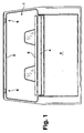
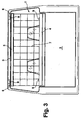
- a cargo space partition according to FIGS. 1 to 6 and 8, 9 has a cassette housing 4 in a basically known manner, that in a vehicle interior 1 on the back of a Backrest arrangement of a rear seat arrangement 2 fixed to the vehicle is positioned.
- the vehicle interior 1 is separated by the cargo space 4, 5, 7 in a passenger compartment or a hold divisible over the entire height of the passenger compartment 1.
- the load compartment partition has a flexible flat structure serving separation network 7 on one in the cassette housing 4 stored roller blinds held and unwound is.
- the separating network 7 is in a front end area connected with a dimensionally stable pull-out profile 5, which extends across the entire width of the separation network 7.
- the pull-out profile 5 has two holding elements spaced apart from one another 8 provided in their functional position (Fig.
- Brackets 6 closes approximately flush with the headlining from the headlining area 3, so that the brackets 6 are sunk behind the headlining.
- the pull-out profile is at least in the area of the arrangement of the two holding elements 8, i.e. in the opposite side Areas, as sections open downwards Hollow profile designed.
- Each holding element 8 is horizontal and pivot axis aligned in the vehicle longitudinal direction 10 pivotally mounted in the pull-out profile 5, so that the holding element 8 approximately in a vertical vehicle transverse plane is pivotable.
- a unspecified Exit slot provided through which the holding element 8th from the sunken rest position (Fig. 4) in the upright position Functional position (Fig. 6) can pass through to the outside. In the upright functional position strikes the holding element 8 on a side stop edge of the exit slot (Figs. 4 to 6).
- Each holding element 8 is by one to the Swivel axis 10 coaxially arranged leg spring 12, 13 in Swinging direction spring-loaded, with a first spring leg 12 on an inner surface of the top of the pull-out profile 5 and a second spring leg 13 on one support bolt 14 integrally formed on the holding element 8 supports.
- the holding element 8 is a positive guidance device 9, 15 assigned by one to one Underside of the holding element 8 provided guide contour 15 on the one hand and one on an upper side of the cassette housing 4 arranged stop surface 9 is formed.
- the guide contour 15 extends relative to the pivot axis 10 of the holding element 8 as well as relative to the direction of movement of the pull-out profile 5 inclined and curved so that during a lowering movement the pull-out profile 5 and an impingement of the guide contour 15 on the stop surface 9 on the holding element 8 shows a torque in the direction of the rest position of the holding element 8 is exercised.
- the guide contour 15 becomes the holding element 8 until it is reached the storage position of the pull-out profile 5 completely in transferred the sunken rest position according to FIG. 4.
- a Another pull-out movement of the pull-out profile 5 comes up the guide contour 15 and the stop surface 9 of the vehicle positioned cassette housing 4 out of plant, whereby the leg spring 12, 13 the holding element 8 automatically in the functional position.
- Each vehicle-fixed bracket 6 is immediately above the Headlining with a plate-like mounting cover 16 provided, the funnel-like in its central region is bulged upwards (Fig. 8, 9).
- the funnel-like bulged area of the aperture 16 is with a slit-shaped passage, the dimensions of which are somewhat larger than the outer contour of the hammer-like head of the holding element 8 - in a plan view in the direction of insertion accordingly Fig. 9 seen - are designed.
- the funnel-shaped Bulge provides a centering aid for inserting the hammer-like Head of the respective holding element 8 represents Receiving panel 16 is in parallel immediately behind the headlining Slidably mounted in the vehicle's longitudinal direction.
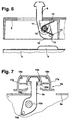
- the design of the receiving area of the base part 18 is recognizable on the basis of the similar exemplary embodiment according to FIG. 7.
- the vehicle-fixed bracket 6a shown there also correspond to the holding element 8a in the pull-out profile 5a from the function and technical design forth the embodiment 1 to 6, 8 and 9, only design Changes in the management of the aperture 16 and of the foot area of the holding element 8a are provided.
- the Embodiment of FIG. 7 the same reference numerals only chosen with the addition of the letter a been.
- the carrier part of the holder 6 forms in a passage area for the holding element 8, an insertion profile 20, the one has a key-like tapered opening 21, 22 (FIG. 9). It connects to a semicircular opening area 21, the width of which is greater than the width of the hammer-like Head of the holding element 8, in the vehicle longitudinal direction a stepped tapered opening area 22 toward the front whose width is slightly larger than the width of the Holding element 8 below the hammer-like head.
- the base part 18 is located on the funnel-shaped bulge opposite side of the Insert profile 20 and thus forms the end stop for the insertion movement of the holding element 8.
- the pull-out profile 5 is pulled up, which automatically Holding elements 8 pressed into their upright functional position become.
- the pull-out profile 5 is pulled up or as far pressed until the holding elements 8 into the funnel-shaped Bulges of the receiving panel 16 of each bracket 6 in Immerse headlining area 3.
- the holding elements 8 and that Pull-out profile 5 are pushed upwards until the Front ends of the hammer-like heads of the holding elements 8 in the Attach the receiving areas of the base parts 18.
Landscapes
- Engineering & Computer Science (AREA)
- Mechanical Engineering (AREA)
- Transportation (AREA)
- Vehicle Step Arrangements And Article Storage (AREA)
- Body Structure For Vehicles (AREA)
Applications Claiming Priority (2)
| Application Number | Priority Date | Filing Date | Title |
|---|---|---|---|
| DE19930107 | 1999-07-01 | ||
| DE19930107A DE19930107C1 (de) | 1999-07-01 | 1999-07-01 | Laderaumabtrennung für ein Kraftfahrzeug |
Publications (2)
| Publication Number | Publication Date |
|---|---|
| EP1065109A2 true EP1065109A2 (fr) | 2001-01-03 |
| EP1065109A3 EP1065109A3 (fr) | 2002-11-20 |
Family
ID=7913148
Family Applications (1)
| Application Number | Title | Priority Date | Filing Date |
|---|---|---|---|
| EP00113045A Withdrawn EP1065109A3 (fr) | 1999-07-01 | 2000-06-23 | Cloisonnement pour coffre de véhicule |
Country Status (5)
| Country | Link |
|---|---|
| US (1) | US6325436B1 (fr) |
| EP (1) | EP1065109A3 (fr) |
| JP (1) | JP2001030839A (fr) |
| KR (1) | KR100644943B1 (fr) |
| DE (1) | DE19930107C1 (fr) |
Cited By (1)
| Publication number | Priority date | Publication date | Assignee | Title |
|---|---|---|---|---|
| FR2915941A1 (fr) * | 2007-05-09 | 2008-11-14 | Cera | Dispositif de fixation d'un filet de protection de compartiment a bagages de vehicule automobile |
Families Citing this family (18)
| Publication number | Priority date | Publication date | Assignee | Title |
|---|---|---|---|---|
| SE514855C2 (sv) * | 1998-04-20 | 2001-05-07 | Volvo Ab | Skyddsanordning för fordon |
| JP2003252127A (ja) | 2001-12-28 | 2003-09-10 | Pioneer Electronic Corp | 駆動制御装置および駆動制御方法 |
| DE10238613A1 (de) * | 2002-08-19 | 2004-03-11 | Bos Gmbh & Co. Kg | Einbaueinheit für ein Kraftfahrzeug |
| US6749241B1 (en) | 2002-08-29 | 2004-06-15 | Collins & Aikman Products | Vehicle cargo panel having retractable belt |
| US7017965B2 (en) * | 2003-08-07 | 2006-03-28 | Bos Gmbh & Co. Kg | Motor-vehicle cargo net |
| DE10356911B3 (de) * | 2003-12-02 | 2005-01-20 | Bos Gmbh & Co. Kg | Laderaumschutzvorrichtung für ein Kraftfahrzeug |
| US7114769B2 (en) * | 2004-06-17 | 2006-10-03 | Asc Incorporated | Automotive vehicle open air system |
| US20050280290A1 (en) * | 2004-06-17 | 2005-12-22 | Urban Michael J | Automotive vehicle open air system |
| US20050280293A1 (en) * | 2004-06-17 | 2005-12-22 | Macnee Arthur L Iii | Automotive vehicle open air system |
| US7163260B2 (en) * | 2004-06-17 | 2007-01-16 | Asc Incorporated | Automotive vehicle open air system |
| DE202005020665U1 (de) * | 2005-07-08 | 2006-05-18 | Bos Gmbh & Co. Kg | Laderaumschutzvorrichtung für ein Kraftfahrzeug |
| DE102005062380B3 (de) * | 2005-12-23 | 2007-03-01 | Dr.Ing.H.C. F. Porsche Ag | Kraftfahrzeug mit einer Befestigungseinrichtung für ein Trenn- bzw. Rückhalteelement |
| DE102006034635A1 (de) * | 2006-07-27 | 2008-01-31 | Dr.Ing.H.C. F. Porsche Ag | Schutzvorrichtung für einen Laderaum |
| US7938483B2 (en) | 2007-05-24 | 2011-05-10 | Specialty Vehicle Acquisition Corp. | Movable vehicular roof |
| US7527328B2 (en) * | 2007-05-24 | 2009-05-05 | Specialty Vehicle Acquisition Corp. | Modular roof system for automotive vehicle |
| US8403615B1 (en) | 2008-08-20 | 2013-03-26 | Bruno Independent Living Aids, Inc. | Vehicle lift barrier |
| US8684645B2 (en) | 2012-03-19 | 2014-04-01 | Kenneth Hobbs | Removable gate |
| DE102012221585B4 (de) * | 2012-11-26 | 2016-11-24 | Bos Gmbh & Co. Kg | Rückhaltevorrichtung für einen Fahrzeuginnenraum |
Family Cites Families (11)
| Publication number | Priority date | Publication date | Assignee | Title |
|---|---|---|---|---|
| DE2750823A1 (de) * | 1977-11-14 | 1979-05-17 | Klaus Zimmermann | Sicherheitsgurteinrichtung in fahrzeugen, insbesondere kraftfahrzeugen |
| JPH0478043U (fr) * | 1990-11-21 | 1992-07-08 | ||
| DE4328746C2 (de) * | 1993-08-26 | 1995-08-24 | Baumeister & Ostler Gmbh Co | Sicherheitsnetzanordnung |
| DE4336380C2 (de) * | 1993-10-25 | 1995-08-10 | Baumeister & Ostler Gmbh Co | Sicherheitsnetzanordnung |
| DE4441610C2 (de) * | 1994-11-23 | 1997-10-02 | Baumeister & Ostler Gmbh Co | Sicherheitsnetzanordnung |
| DE19531303C1 (de) * | 1995-08-25 | 1997-02-06 | Baumeister & Ostler Gmbh Co | Laderaumabtrennung zwischen einem Fondraum und einem Laderaum eines Innenraumes eines Kombi-Personenkraftwagens |
| US5772370A (en) * | 1995-11-22 | 1998-06-30 | Moore; Donal | Retractable and/or removable net type cargo restraining system |
| KR100197002B1 (ko) * | 1995-12-02 | 1999-06-15 | 정몽규 | 화물차용 적재함의 로프 고정고리 |
| US5702143A (en) * | 1996-03-15 | 1997-12-30 | Tachi-S Co., Ltd. | Arrangement for anchoring a guard net in automobile |
| KR0130459Y1 (ko) * | 1996-09-17 | 1998-12-15 | 박병재 | 자동차의 화물 고정용 네트 후크 |
| DE19728587C1 (de) * | 1997-07-04 | 1998-11-05 | Baumeister & Ostler Gmbh Co | Sicherheitsnetzanordnung mit Belastungsanzeige |
-
1999
- 1999-07-01 DE DE19930107A patent/DE19930107C1/de not_active Expired - Fee Related
-
2000
- 2000-06-15 JP JP2000184592A patent/JP2001030839A/ja active Pending
- 2000-06-23 EP EP00113045A patent/EP1065109A3/fr not_active Withdrawn
- 2000-07-01 KR KR1020000037552A patent/KR100644943B1/ko not_active Expired - Fee Related
- 2000-07-03 US US09/609,365 patent/US6325436B1/en not_active Expired - Fee Related
Non-Patent Citations (1)
| Title |
|---|
| None |
Cited By (1)
| Publication number | Priority date | Publication date | Assignee | Title |
|---|---|---|---|---|
| FR2915941A1 (fr) * | 2007-05-09 | 2008-11-14 | Cera | Dispositif de fixation d'un filet de protection de compartiment a bagages de vehicule automobile |
Also Published As
| Publication number | Publication date |
|---|---|
| DE19930107C1 (de) | 2000-07-13 |
| JP2001030839A (ja) | 2001-02-06 |
| KR100644943B1 (ko) | 2006-11-10 |
| US6325436B1 (en) | 2001-12-04 |
| EP1065109A3 (fr) | 2002-11-20 |
| KR20010029876A (ko) | 2001-04-16 |
Similar Documents
| Publication | Publication Date | Title |
|---|---|---|
| DE19930107C1 (de) | Laderaumabtrennung für ein Kraftfahrzeug | |
| DE19605907B4 (de) | Sicherungsvorrichtung für einen Innenraum eines Kraftfahrzeugs | |
| DE10320527B3 (de) | Trennvorrichtung für einen Fahrzeuginnenraum | |
| EP1479564B1 (fr) | dispositif de protection pour intérieur véhicule | |
| EP1574394B1 (fr) | Unité fonctionelle pour l'habitacle d'un véhicule | |
| EP1068100B1 (fr) | Espace de chargement d'automobile et dispositif de segmentation | |
| DE10117837A1 (de) | Laderaumabdeckvorrichtung für ein Kraftfahrzeug | |
| DE19940602A1 (de) | Laderaumabdeckung für ein Kraftfahrzeug | |
| EP1247693B1 (fr) | Couvercle pour le compartiment à bagages d'un véhicule | |
| DE4124449A1 (de) | Modulares gepaecksicherungssystem | |
| DE102012204655B4 (de) | Haltevorrichtung für ein Rollogehäuse in einem Fahrzeuginnenraum | |
| DE10223684B4 (de) | Fahrzeugraum mit wenigstens einem, auf-und abwickelbaren, flexiblen Flächengebilde | |
| DE10239200B4 (de) | Windschutzanordnung mit einem Teleskopelement sowie Fahrzeug mit einer derartigen Windschutzanordnung | |
| DE102010025213B4 (de) | Schutzvorrichtung für einen Fahrzeuginnenraum | |
| DE10224368B4 (de) | Funktionseinrichtung für ein Kraftfahrzeug | |
| DE4128701A1 (de) | Schutzwand zur abtrennung des fahrgastraumes eines kraftfahrzeuges von einem dahinter gelegenen laderaum | |
| DE602005001587T2 (de) | Rollo für Gepäckraumabdeckung für ein Kraftfahrzeug und hiermit ausgestattetes Fahrzeug | |
| DE19543349C1 (de) | Windschott für zwei Frontsitze eines offenen Personenkraftwagens | |
| DE102006008653A1 (de) | Windstoppeinrichtung für ein Cabrioletfahrzeug | |
| DE10023706C1 (de) | Rückhaltevorrichtung für den Laderaum von Kraftfahrzeugen, wie z.B. von Kombinationskraftwagen od. dgl. | |
| DE10134613A1 (de) | Hinter Vordersitzen eines cabrioartigen Fahrzeugs aufspannbares Windschott | |
| EP0943498A1 (fr) | Disposition de sécurisation de charge | |
| DE102007015075B4 (de) | Befestigungseinrichtung für Funktionseinrichtungen in Fahrzeugen | |
| DE19605338A1 (de) | Sicherungsvorrichtung für einen Innenraum eines Kraftfahrzeugs | |
| DE10063728B4 (de) | Kofferraum für einen Personenkraftwagen |
Legal Events
| Date | Code | Title | Description |
|---|---|---|---|
| PUAI | Public reference made under article 153(3) epc to a published international application that has entered the european phase |
Free format text: ORIGINAL CODE: 0009012 |
|
| AK | Designated contracting states |
Kind code of ref document: A2 Designated state(s): AT BE CH CY DE DK ES FI FR GB GR IE IT LI LU MC NL PT SE |
|
| AX | Request for extension of the european patent |
Free format text: AL;LT;LV;MK;RO;SI |
|
| PUAL | Search report despatched |
Free format text: ORIGINAL CODE: 0009013 |
|
| AK | Designated contracting states |
Kind code of ref document: A3 Designated state(s): AT BE CH CY DE DK ES FI FR GB GR IE IT LI LU MC NL PT SE |
|
| AX | Request for extension of the european patent |
Free format text: AL;LT;LV;MK;RO;SI |
|
| 17P | Request for examination filed |
Effective date: 20030401 |
|
| AKX | Designation fees paid |
Designated state(s): DE FR GB IT |
|
| 17Q | First examination report despatched |
Effective date: 20061121 |
|
| STAA | Information on the status of an ep patent application or granted ep patent |
Free format text: STATUS: THE APPLICATION IS DEEMED TO BE WITHDRAWN |
|
| 18D | Application deemed to be withdrawn |
Effective date: 20091231 |