EP1065113A2 - Tankstelle mit einem Sensor für elektromagnetische Welle - Google Patents
Tankstelle mit einem Sensor für elektromagnetische Welle Download PDFInfo
- Publication number
- EP1065113A2 EP1065113A2 EP99306998A EP99306998A EP1065113A2 EP 1065113 A2 EP1065113 A2 EP 1065113A2 EP 99306998 A EP99306998 A EP 99306998A EP 99306998 A EP99306998 A EP 99306998A EP 1065113 A2 EP1065113 A2 EP 1065113A2
- Authority
- EP
- European Patent Office
- Prior art keywords
- fueling
- electromagnetic
- gas station
- wave sensor
- unit
- Prior art date
- Legal status (The legal status is an assumption and is not a legal conclusion. Google has not performed a legal analysis and makes no representation as to the accuracy of the status listed.)
- Granted
Links
Images



Classifications
-
- B—PERFORMING OPERATIONS; TRANSPORTING
- B67—OPENING, CLOSING OR CLEANING BOTTLES, JARS OR SIMILAR CONTAINERS; LIQUID HANDLING
- B67D—DISPENSING, DELIVERING OR TRANSFERRING LIQUIDS, NOT OTHERWISE PROVIDED FOR
- B67D7/00—Apparatus or devices for transferring liquids from bulk storage containers or reservoirs into vehicles or into portable containers, e.g. for retail sale purposes
- B67D7/06—Details or accessories
- B67D7/08—Arrangements of devices for controlling, indicating, metering or registering quantity or price of liquid transferred
-
- B—PERFORMING OPERATIONS; TRANSPORTING
- B60—VEHICLES IN GENERAL
- B60S—SERVICING, CLEANING, REPAIRING, SUPPORTING, LIFTING, OR MANOEUVRING OF VEHICLES, NOT OTHERWISE PROVIDED FOR
- B60S5/00—Servicing, maintaining, repairing, or refitting of vehicles
- B60S5/02—Supplying fuel to vehicles; General disposition of plant in filling stations
-
- G—PHYSICS
- G01—MEASURING; TESTING
- G01R—MEASURING ELECTRIC VARIABLES; MEASURING MAGNETIC VARIABLES
- G01R29/00—Arrangements for measuring or indicating electric quantities not covered by groups G01R19/00 - G01R27/00
- G01R29/08—Measuring electromagnetic field characteristics
- G01R29/0807—Measuring electromagnetic field characteristics characterised by the application
- G01R29/0814—Field measurements related to measuring influence on or from apparatus, components or humans, e.g. in ESD, EMI, EMC, EMP testing, measuring radiation leakage; detecting presence of micro- or radiowave emitters; dosimetry; testing shielding; measurements related to lightning
- G01R29/0857—Dosimetry, i.e. measuring the time integral of radiation intensity; Level warning devices for personal safety use
Definitions
- the present invention relates to a gas station with an electromagnetic-wave sensor, more precisely a gas station wherein electromagnetic waves, which are generated by a portable phone or like, are detected by a sensor therefor and the detection is notified to people by the provision of communicators.
- a weak electric current generates on a portable telephone in the case of the outgoing and incoming thereof.
- a gas station where fuel runs from a fueling port and fuel vapor remains around fueling units, it is desirable to grasp the use state of the portable telephone to take an appropriate measure.
- a gas station comprising one or more fueling units; an electromagnetic-wave sensor for detecting electromagnetic waves which are unwanted in fueling operation; and one or more communicators for showing the electromagnetic-wave detection by the electromagnetic-wave sensor, the electromagnetic-wave sensor being provided outside the fueling units.
- the object of the present invention can be achieved also by a gas station comprising one or more fueling units; one or more electromagnetic-wave sensors for detecting electromagnetic waves which are unwanted for fueling operation; and one or more communicators for showing the electromagnetic-wave detection by the electromagnetic-wave sensor, each of the fueling unit containing the electromagnetic-wave sensor.
- the gas station of the present invention comprises one or more fueling units; an electromagnetic-wave sensor for detecting electromagnetic waves which are unwanted in fueling operation; and one or more communicators for showing the electromagnetic-wave detection by the electromagnetic-wave sensor, the electromagnetic-wave sensor being provided outside the fueling units.
- the gas station comprising one or more fueling units; one or more electromagnetic-wave sensors for detecting electromagnetic waves which are unwanted in fueling operation; and one or more communicators for showing the electromagnetic-wave detection by the electromagnetic-wave sensor, each of the fueling unit containing the electromagnetic-wave sensor.
- the electromagnetic-wave sensor for use in the present invention is provided outside the fueling unit in a location from which unwanted electromagnetic waves (hereinafter, may be referred to as electromagnetic waves) in the gas station are well sensed, preferably at the inner surface of the canopy (roof) of the gas station at the center thereof.
- electromagnetic waves unwanted electromagnetic waves
- the electromagnetic-wave sensor can be provided in each of the fueling units. In the latter case, it is easy to know around which fueling unit a portable telephone or the like is used.
- the gas station of the present invention further comprise a fuel-manage unit.
- the fuel-manage unit transmits a detection signal is transmitted to the communicators which shows the detection thereon, whereby it becomes possible to urge people in the gas station not to use of a portable phone in the gas station and to prevent the fuel vapor generation by suspending the fueling in accordance with the notice by the communicators.
- the fueling unit of the present invention preferably comprise a control unit in each of the fueling units.
- the fueling can be suspended by the receipt of a signal from the control units after the detection signal being transmitted thereto via the above-mentioned fuel-manage unit or directly from the electromagnetic-wave sensors provided in each of the fueling units. Thus, the fueling can be suspended.
- the communicators for use in the present invention can be provided in the gas station for instance on each of the fueling unit, in an office within the gas station, and outside the office.
- the communicators can be provided in the gas station for instance on each of the fueling unit, in an office within the gas station, and outside the office.
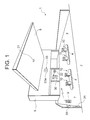
- a gas station 1 as a first embodiment of the present invention faces a road 2.
- the site 3 of gas station 1 there are islands 4 on each of which two fueling units 10 are provided.
- an office building 5 is there wherein a fuel-manage unit 30 and an indoor communicator 32 are provided.
- An outdoor communicator 33 is provided on the outside wall of the office building 5 in such a fashion that the communicator 33 can be seen from almost all parts within the site 3.
- a canopy 6 covers the site 3 extending from the front upper surface of the building 5 to the part above the fueling units 10.
- An electromagnetic-wave sensor 31 is provided on the canopy 6 on the lower surface thereof, for detecting electromagnetic waves generated from a portable telephone 9 employed in the site 3.
- the sensor 31 detects, for instance, electromagnetic waves with a predetermined frequency generated from the portable phone 9 located in the range of about 10 meters therefrom.
- Nearby an entrance 7 of a car there are also provided an entrance sensor 34 for detecting the entrance of a car to the site 3, and an information machine 35 from which voice is output based upon the detection signal from the entrance sensor 34, for giving notice not to use a portable phone within the site 3.
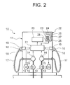
- Fig. 2 shows a schematic diagram of the fueling unit 10 to be used in the gas station as the first embodiment of the present invention.
- the fueling unit 10 supplies, for example, two kinds of fuels.
- a casing 11 contains fueling pumps 13 which can be driven by means of pump-drive-motors 12, and flow-meters 15 with flow-volume-pulse generator 14 thereon, being successively connected on fueling pipes to the underground tanks. Furthermore, pipes connected to the outlets of the flow meters 15 are led to the outside of the casing 11, connected to fueling hoses 17 with fueling nozzles 16 at the free ends thereof. Nozzle rests 18 for hanging the fueling nozzles 16 thereon are provided on the casing 11, with nozzle switches 19 being arranged nearby the nozzle rests 18.
- a control unit 21 is provided in the casing 11, which controls the movement of the pump-drive-motors 12 in response to signals from nozzle switches 19 and a fuel-manage unit (to be explained below in detail), the control unit 21 also controlling the indication onto a display 20 of the fueled volume by calculating the flow volume of fuel by integrating pulses output from the flow-volume-pulse generator 14.
- the operation panel 22 contains thereon a keyboard 23 for selecting the fuel sort and fueling volume; a panel indicator 24 for indicating the data input from the keyboard 23 and information obtained from the fuel-manage unit via the control unit 21; a panel communicator 25 for indicating information from the fuel-manage unit via the control unit 21 or from the control unit 25 itself; a printer 26 for issuing a fueling bill; a card reader 27; and a re-fuel switch 28 for starting fueling again after the suspension of fueling.
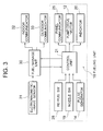
- the control unit 21 and the fuel-manage unit 30 are connected each other for the signal transmission therebetween.
- the control unit 21 contained in the fueling unit 10 transmits a signal relating to fuel volume or the like to the fuel-manage unit 30.
- the fuel-manage unit 30 outputs a signal for controlling the fueling unit 10 to the control unit 21.
- the fuel-manage unit 30 for use in the present invention is a unit for receiving signals from the fueling units 10, transferring the signals to POS terminal (not shown) or the like, and transmitting signals detected by the electromagnetic-wave sensor 31 to the pump-drive-motors 12 to make the pumps to stop and drive again.
- the fuel-manage unit 30 also outputs signals for controlling the indoor and outdoor communicators 32 and 33.
- the control unit 21 further receives signals from the re-fuel switch 28, nozzle switch 19, and flow-volume-pulse generator 14, and outputs signals to the panel communicator 25, pump-drive-motors 12, and the indicator 20.
- the indoor communicator 32 installed in the office building 5 notices information to people therein, the indoor communicator 32 being provided with a portable-telephone-use-state communicator 32a on the front surface thereof.
- the communicator can be designed as a device showing indication by light or sound.
- the outdoor communicator 33 is provided on the outer wall of the building 5 at a front upper part as can be seen from customers and clerks in the site 3 .
- the outdoor communicator 33 has a portable-telephone-use-state communicator 33a, which makes communication by means of light or sound, on the front surface thereof.
- the information machine 35 outputs message not to use a portable telephone to customers when the entrance sensor 34 detects an automobile entering to the gas station through the entrance 7 as mentioned previously. Accordingly, the customers recognizes beforehand that the use of portable telephones are prohibited within the site 3 of the gas station.
- the customer may use a portable telephone 9.
- the electromagnetic-wave sensor 31 is employed in the present invention. As explained in the flow-chart in Fig.
- the fuel-manage unit 30 when the electromagnetic-wave sensor 31 detects electromagnetic waves generated from a portable telephone 9 (ST 1), the fuel-manage unit 30 transmits a detection signal to the outdoor and indoor communicators 32 and 33, simultaneously with transmitting the detection signal to each of the fueling units 10 (ST 2), to make indication on the panel communicator 25 and panel indicator 24 provided on each of the fueling units 10.
- the communicating state is maintained while the electromagnetic waves are being detected by the electromagnetic-wave sensor 31.
- the fuel-manage unit 30 When it becomes that the electromagnetic waves are not detected any more (ST 3), the fuel-manage unit 30 outputs a signal to stopping the communication made by the indoor and outdoor communicators 32 and 33, with transmitting a non-detection signal to the fuel units 10 (ST 4), whereby the indication by the panel communicator 25 and panel indicator 24 on each of the fueling unit 10 are canceled.
- Fig. 5 shows a flow-chart for explaining the function of the fueling units 10 for use in the present invention.
- the control unit 21 brings the indicator 20 back to zero, and causes the pump-drive-motor 12 to be driven (ST 12). Subsequently, when the fuel lever is pulled up upon the fueling nozzle 16 inserted to the fueling tank-port of a car, fuel oil runs into the tank through the fueling pump 13, a flow-volume-pulse signal is output from the flow-volume-pulse generator 14 (ST 13) and the fueled volume is indicated on the indicator 20 after the flow-volume pulse is integrated (ST 14). With the completion of fueling, the nozzle switch 19 is turned off (ST 15), and then the pump-drive-motor 12 is cause to stop driving and the fueling pump 13 is stopped (ST 16).
- the control unit 21 cause to stop the pump-drive-motors 12 and hence the pumps (ST 18).
- the suspension state of the pump-drive-motors 12 is maintained as long as the detection signal is being obtained from the fuel-manage unit 30 as the result of the detection by the electromagnetic-wave sensor 31.
- the electromagnetic-wave sensor 31 does not receive the electromagnetic waves any more (ST 19) and the re-fuel switch 28 is turned on (ST 20), the pump-drive-motor 12 is started to be driven again (ST 21).
- the system comes back to the step 13 where the flow-volume pulse is counted.
- the gas station with the above-mentioned structure, it is possible to urge people therein to be stop the use of a portable phone 9, since the voice machine 35 gives customers messages not to use portable phones 9 as precisely described.
- the electromagnetic-wave sensor 31 provided for instance on the lower surface of the canopy 6 and communicators 32 and 33 work and clerks and customers inside or outside the office building 5 could know the caution, whereby fueling can be suspended.
- a plurality of fueling units 40 as shown by the front view of Fig. 6 are installed in the gas station in the same way as in the perspective view in Fig. 1.
- the fueling unit 40 dispenses fuels such as premium, regular, and diesel, of which casing 41 is composed of a main-body casing 42, an indictor casing 43 placed thereon, and a top part casing 45 over the indication casing 43 supported by posts 44.
- the fueling unit 40 is constructed substantially in the same way as in Fig. 1.
- Fig. 6 there are provided in the fueling unit 40, pump-drive-motors 46 for driving pumps (not shown), and flow meters each provided with flow-volume-pulse generators 47.
- pump-drive-motors 46 for driving pumps (not shown)
- flow meters each provided with flow-volume-pulse generators 47.
- fueling hoses 48 are connected each at one end thereof and are suspended.
- the fueling hoses 48 have fueling nozzles 49 at the free ends thereof which can be hung on nozzle rests 50 provided on the main-body casing 42 at the front and back sides thereof.
- Nozzle switches 51 are formed nearby nozzle rests 50.
- indicators 52 for indicating the fueled volume, on the front and back surfaces of the indication casing 43.
- An operation panel 53 is provided below the indicator 52.
- the operation panel 53 comprises a keyboard 54 for adjusting fuel sorts and volume; a panel indicator 55 for indicating the input data from the keyboard 54 and information obtained as a signal from a fuel-manage unit (not shown); a panel communicator 56 from which notice is made as light or sound; and a re-fuel switch 57 which is to be pressed when it becomes necessary to start fueling again after the suspension of fueling.
- signal transmission is performed by way of a control unit 58 contained in the indication casing 43.
- an electromagnetic-wave sensor 59 for detecting electromagnetic waves generated from a portable telephone 9 or the like is adjusted on the top casing 45 at the lower surface thereof.
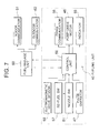
- the signal transmission in the fueling unit 40 is explained with referring to a block diagram shown in Fig. 7.
- the signal detected by the electromagnetic-wave sensor 59 in the fueling unit 40 is transferred to the control unit 58.
- the control unit 58 which has received the detection signal can stop the pump-drive-motors 46 working and causes the panel communicator 56 and panel indicator 55 to give indication. Furthermore, the control unit 58 receives signals from the re-fuel switch 57, nozzle switches 51, and flow-volume-pulse generators 47, and turns on and off the pump-drive-motors 46.
- the control unit 58 is connected to a fuel-manage unit 60 which is provided in an office building also in the second embodiment as explained in the first embodiment, and the signal transmission is carried out therebetween.
- the fuel-manage unit 60 transmits signals to an indoor communicator 61 and an outdoor communicator 62. Namely, the fuel-manage unit 60, which has received a detection signal from the electromagnetic-wave sensor 59 provided in the fueling unit 40, causes to function the indoor communicator 61 and outdoor communicator 62.
- Fig. 8 is a view for showing the indoor communicator 61 as an example, seen from the front.
- an fueling-unit-identification panel 61a and a portable-telephone-use-state indicator 61b which indicate the use of a portable phone by means of light or sound.
- Fig 9 shows the outdoor communicator 62, as a diagram seen from the front, as an example.
- the outdoor communicator 62 also comprises an fueling-unit-identification panel 62a on which numbers corresponding to the fuel units 40 are shown, and a portable-telephone-use-state indicator 62b by which the use of a portable phone is indicated by means of light or sound.
- the signal transmission is performed essentially in the same way as in the first embodiment explained with referring to Figs. 4 and 5.
- the electromagnetic-wave sensor 59 is provided in each of the fueling units 40.
- the control unit 58 can directly controls the pump-drive-motor 46 to suspend the fueling, cause the panel communicator 56 and panel indicator 55 to show the detection, and transmits the detection signal to the fuel-manage unit 60 provided in the office building.
- the fuel-manage unit 60 controls the indoor and outdoor communicators 61 and 62, respectively on which the portable-telephone-use-state indicators 61b and 62b are cause to work.
- the fuel-manage unit 60 outputs a signal for turning off the indoor and outdoor communicators 61 and 62 upon the receipt of the non-detection signal transmitted from the control unit 58.
- the clerks in the office or outside the office can readily recognize which electromagnetic-wave sensor 59 in which fueling unit 40 has detected magnetic waves generated, for instance, by the use of a portable telephone 9 since the indoor and outdoor communicators 61 and 62 identify the fueling unit 40. Thus, the clerk can advise the telephone user not to use the phone.
- the electromagnetic waves are generated from a portable phone.
- the electromagnetic waves which are detected by the electromagnetic-wave sensors 31, 59 for use in the present invention are not always generated from a portable phone.
- the indoor communicators 32 and 61, the outdoor communicators 33 and 62 can shows the detection by light-on, light-on-and-off, a sound of buzzer or the like.
- the panel communicators 25 and 56 also can be designed as outputting light or sound by which the detection signal is notified to people there. It is a matter of course that the indication on the panel displays 24 and 55 can be made by use of letters, characters, pictures or the like.
- the fueling unit for use in the present invention may only have either one of the panel communicator or panel display.
- the gas station according to the present invention comprises one or more of electromagnetic-wave sensors and communicators, thereby giving service in an excellent condition.
Landscapes
- Engineering & Computer Science (AREA)
- Mechanical Engineering (AREA)
- Chemical & Material Sciences (AREA)
- Chemical Kinetics & Catalysis (AREA)
- General Chemical & Material Sciences (AREA)
- Oil, Petroleum & Natural Gas (AREA)
- Physics & Mathematics (AREA)
- Mathematical Physics (AREA)
- Theoretical Computer Science (AREA)
- Loading And Unloading Of Fuel Tanks Or Ships (AREA)
Applications Claiming Priority (2)
| Application Number | Priority Date | Filing Date | Title |
|---|---|---|---|
| JP18725399A JP3460629B2 (ja) | 1999-07-01 | 1999-07-01 | 給油所 |
| JP18725399 | 1999-07-01 |
Publications (3)
| Publication Number | Publication Date |
|---|---|
| EP1065113A2 true EP1065113A2 (de) | 2001-01-03 |
| EP1065113A3 EP1065113A3 (de) | 2003-02-12 |
| EP1065113B1 EP1065113B1 (de) | 2004-08-25 |
Family
ID=16202743
Family Applications (1)
| Application Number | Title | Priority Date | Filing Date |
|---|---|---|---|
| EP99306998A Expired - Lifetime EP1065113B1 (de) | 1999-07-01 | 1999-09-03 | Tankstelle mit einem Sensor für elektromagnetische Welle |
Country Status (7)
| Country | Link |
|---|---|
| US (1) | US6191695B1 (de) |
| EP (1) | EP1065113B1 (de) |
| JP (1) | JP3460629B2 (de) |
| KR (1) | KR100413247B1 (de) |
| CN (1) | CN1123776C (de) |
| DE (1) | DE69919687T2 (de) |
| ES (1) | ES2227974T3 (de) |
Cited By (4)
| Publication number | Priority date | Publication date | Assignee | Title |
|---|---|---|---|---|
| GB2360863A (en) * | 1999-11-15 | 2001-10-03 | Scott C Harris | Detecting communication device at a fuel station and providing protection |
| FR2813072A1 (fr) * | 2000-07-14 | 2002-02-22 | Tokheim Corp | Systeme de commande automatique pour distributeur de carburant, utilisant une detection de signal radiofrequence |
| EP1609688A3 (de) * | 2004-06-25 | 2007-10-17 | MM Petro sp. z o.o. | Flüssigkeitsspender |
| US20240025378A1 (en) * | 2022-07-25 | 2024-01-25 | Fire & Risk Alliance, LLC | Method for hazard detection and fire prevention in a mobile refueling system |
Families Citing this family (14)
| Publication number | Priority date | Publication date | Assignee | Title |
|---|---|---|---|---|
| IL132973A (en) * | 1999-11-16 | 2001-06-14 | Litt Aryeh | Gasoline pump |
| US6935356B2 (en) * | 2003-03-14 | 2005-08-30 | Gilbarco Inc. | Underground storage tank metering system in a service station environment |
| CA2423938C (en) * | 2003-03-28 | 2011-08-09 | Trillium Fueling Systems Inc. | Modular above ground fueling station and method of construction thereof |
| US20050001722A1 (en) * | 2003-07-03 | 2005-01-06 | Lin Davis | Fuel dispenser ignition source detector |
| US7558044B2 (en) * | 2005-02-04 | 2009-07-07 | George Kent J | Static electricity eliminator |
| US7523770B2 (en) * | 2005-12-12 | 2009-04-28 | Exxonmobil Research And Enginnering Company | Service station for serving requirements of multiple vehicle technologies |
| US20090045925A1 (en) * | 2007-08-17 | 2009-02-19 | Franklin Fueling Systems, Inc. | System, Apparatus, and Method for Communicating Sensor Information of a System Component that is Disposed in a Hazardous Location |
| US10839402B1 (en) | 2014-03-24 | 2020-11-17 | EMC IP Holding Company LLC | Licensing model for tiered resale |
| WO2018017300A1 (en) * | 2016-07-22 | 2018-01-25 | Exxonmobil Research And Engineering Company | System and method for fueling location recommendations |
| CN107947895B (zh) * | 2018-01-08 | 2019-11-08 | 全民福网络科技有限公司 | 加油站屏蔽信号的装置及系统 |
| TWI681368B (zh) * | 2018-05-17 | 2020-01-01 | 力歐新能源股份有限公司 | 油電共用續能站之異常偵測設備及其方法 |
| JP6821135B2 (ja) * | 2019-02-21 | 2021-01-27 | Nl技研株式会社 | 通信機器 |
| CN110682860B (zh) * | 2019-09-19 | 2021-08-06 | 佛吉亚歌乐电子(丰城)有限公司 | 一种针对加油站内通话的车载智能报警方法及其系统 |
| CN117212698A (zh) * | 2023-09-18 | 2023-12-12 | 东风汽车集团股份有限公司 | 燃料站的安全保障方法、系统及设备 |
Family Cites Families (6)
| Publication number | Priority date | Publication date | Assignee | Title |
|---|---|---|---|---|
| US5364291A (en) * | 1992-09-28 | 1994-11-15 | Japan Aviation Electronics Industry, Ltd. | Connector covered with conductive front and back shells and comprising a resilient conductive member between the shells |
| US5543779A (en) * | 1995-03-09 | 1996-08-06 | Aspesi; Marc S. | EMI source detector |
| FR2762428B1 (fr) * | 1997-04-16 | 1999-06-11 | Schlumberger Ind Sa | Dispositif de visualisation d'un message sur un distributeur de carburant |
| JPH10336101A (ja) * | 1997-05-30 | 1998-12-18 | Oki Electric Ind Co Ltd | 携帯電話の使用管理システム |
| JP4126714B2 (ja) * | 1999-06-25 | 2008-07-30 | 株式会社タツノ・メカトロニクス | 給油装置 |
| JP3975313B2 (ja) * | 1999-06-28 | 2007-09-12 | 株式会社タツノ・メカトロニクス | 給油所用注油管理装置 |
-
1999
- 1999-07-01 JP JP18725399A patent/JP3460629B2/ja not_active Expired - Fee Related
- 1999-07-16 KR KR10-1999-0028857A patent/KR100413247B1/ko not_active Expired - Fee Related
- 1999-08-03 CN CN99111247A patent/CN1123776C/zh not_active Expired - Fee Related
- 1999-09-03 EP EP99306998A patent/EP1065113B1/de not_active Expired - Lifetime
- 1999-09-03 ES ES99306998T patent/ES2227974T3/es not_active Expired - Lifetime
- 1999-09-03 DE DE69919687T patent/DE69919687T2/de not_active Expired - Fee Related
- 1999-09-09 US US09/392,479 patent/US6191695B1/en not_active Expired - Fee Related
Non-Patent Citations (1)
| Title |
|---|
| None |
Cited By (6)
| Publication number | Priority date | Publication date | Assignee | Title |
|---|---|---|---|---|
| GB2360863A (en) * | 1999-11-15 | 2001-10-03 | Scott C Harris | Detecting communication device at a fuel station and providing protection |
| GB2360863B (en) * | 1999-11-15 | 2002-08-28 | Scott C Harris | Automatic cell phone detection at a combustible delivery station |
| FR2813072A1 (fr) * | 2000-07-14 | 2002-02-22 | Tokheim Corp | Systeme de commande automatique pour distributeur de carburant, utilisant une detection de signal radiofrequence |
| EP1609688A3 (de) * | 2004-06-25 | 2007-10-17 | MM Petro sp. z o.o. | Flüssigkeitsspender |
| US20240025378A1 (en) * | 2022-07-25 | 2024-01-25 | Fire & Risk Alliance, LLC | Method for hazard detection and fire prevention in a mobile refueling system |
| US12233825B2 (en) * | 2022-07-25 | 2025-02-25 | Fire & Risk Alliance, LLC | Method for hazard detection and fire prevention in a mobile refueling system |
Also Published As
| Publication number | Publication date |
|---|---|
| KR100413247B1 (ko) | 2003-12-31 |
| KR20010010138A (ko) | 2001-02-05 |
| CN1279402A (zh) | 2001-01-10 |
| CN1123776C (zh) | 2003-10-08 |
| US6191695B1 (en) | 2001-02-20 |
| EP1065113B1 (de) | 2004-08-25 |
| DE69919687D1 (de) | 2004-09-30 |
| ES2227974T3 (es) | 2005-04-01 |
| EP1065113A3 (de) | 2003-02-12 |
| JP2001019100A (ja) | 2001-01-23 |
| JP3460629B2 (ja) | 2003-10-27 |
| DE69919687T2 (de) | 2005-09-08 |
Similar Documents
| Publication | Publication Date | Title |
|---|---|---|
| EP1065113B1 (de) | Tankstelle mit einem Sensor für elektromagnetische Welle | |
| US6363299B1 (en) | Dispenser system for preventing unauthorized fueling | |
| JP4216952B2 (ja) | セルフ給油システム | |
| JP2007293795A (ja) | 給油装置 | |
| US5735435A (en) | Fuel dispenser with seismic vibration perception function. | |
| JP3460628B2 (ja) | 給油管理装置 | |
| JP2001019099A (ja) | 給油装置 | |
| JP2001002198A (ja) | 給油装置 | |
| US6488057B1 (en) | Fueling system | |
| JPH064778A (ja) | 給油所用posシステム | |
| JP3496758B2 (ja) | 給油装置 | |
| JP2001002197A (ja) | 給油所用注油管理装置 | |
| JPS61152595A (ja) | 給油装置 | |
| JPH05338700A (ja) | 給油制御装置 | |
| KR100201344B1 (ko) | 급유장치 | |
| JPH055287B2 (de) | ||
| JP2000159298A (ja) | 給油装置 | |
| JPH0342502Y2 (de) | ||
| JPH0597192A (ja) | Lpg充填装置 | |
| KR960034067A (ko) | 급유소 설비 | |
| JP2022082212A (ja) | セルフ給油システム | |
| EP3392546A1 (de) | Gasfüllvorrichtung | |
| WO2004072602A1 (en) | A valve arrangement | |
| JPS5899394A (ja) | 給油所 | |
| JP2005306461A (ja) | 給油所用posシステム及び給油システム |
Legal Events
| Date | Code | Title | Description |
|---|---|---|---|
| PUAI | Public reference made under article 153(3) epc to a published international application that has entered the european phase |
Free format text: ORIGINAL CODE: 0009012 |
|
| AK | Designated contracting states |
Kind code of ref document: A2 Designated state(s): AT BE CH CY DE DK ES FI FR GB GR IE IT LI LU MC NL PT SE |
|
| AX | Request for extension of the european patent |
Free format text: AL;LT;LV;MK;RO;SI |
|
| PUAL | Search report despatched |
Free format text: ORIGINAL CODE: 0009013 |
|
| AK | Designated contracting states |
Designated state(s): AT BE CH CY DE DK ES FI FR GB GR IE IT LI LU MC NL PT SE |
|
| AX | Request for extension of the european patent |
Extension state: AL LT LV MK RO SI |
|
| RIC1 | Information provided on ipc code assigned before grant |
Ipc: 7B 67D 5/32 B Ipc: 7B 60S 5/02 A |
|
| 17P | Request for examination filed |
Effective date: 20030326 |
|
| 17Q | First examination report despatched |
Effective date: 20030604 |
|
| AKX | Designation fees paid |
Designated state(s): BE DE ES FR GB NL |
|
| GRAP | Despatch of communication of intention to grant a patent |
Free format text: ORIGINAL CODE: EPIDOSNIGR1 |
|
| GRAS | Grant fee paid |
Free format text: ORIGINAL CODE: EPIDOSNIGR3 |
|
| GRAA | (expected) grant |
Free format text: ORIGINAL CODE: 0009210 |
|
| GRAL | Information related to payment of fee for publishing/printing deleted |
Free format text: ORIGINAL CODE: EPIDOSDIGR3 |
|
| GRAS | Grant fee paid |
Free format text: ORIGINAL CODE: EPIDOSNIGR3 |
|
| AK | Designated contracting states |
Kind code of ref document: B1 Designated state(s): BE DE ES FR GB NL |
|
| REG | Reference to a national code |
Ref country code: GB Ref legal event code: FG4D |
|
| REG | Reference to a national code |
Ref country code: IE Ref legal event code: FG4D |
|
| REF | Corresponds to: |
Ref document number: 69919687 Country of ref document: DE Date of ref document: 20040930 Kind code of ref document: P |
|
| ET | Fr: translation filed | ||
| REG | Reference to a national code |
Ref country code: ES Ref legal event code: FG2A Ref document number: 2227974 Country of ref document: ES Kind code of ref document: T3 |
|
| REG | Reference to a national code |
Ref country code: IE Ref legal event code: MM4A |
|
| PLBE | No opposition filed within time limit |
Free format text: ORIGINAL CODE: 0009261 |
|
| STAA | Information on the status of an ep patent application or granted ep patent |
Free format text: STATUS: NO OPPOSITION FILED WITHIN TIME LIMIT |
|
| 26N | No opposition filed |
Effective date: 20050526 |
|
| PGFP | Annual fee paid to national office [announced via postgrant information from national office to epo] |
Ref country code: GB Payment date: 20070815 Year of fee payment: 9 |
|
| PGFP | Annual fee paid to national office [announced via postgrant information from national office to epo] |
Ref country code: NL Payment date: 20070930 Year of fee payment: 9 Ref country code: ES Payment date: 20071029 Year of fee payment: 9 Ref country code: BE Payment date: 20070905 Year of fee payment: 9 |
|
| PGFP | Annual fee paid to national office [announced via postgrant information from national office to epo] |
Ref country code: FR Payment date: 20070831 Year of fee payment: 9 |
|
| PGFP | Annual fee paid to national office [announced via postgrant information from national office to epo] |
Ref country code: DE Payment date: 20080919 Year of fee payment: 10 |
|
| BERE | Be: lapsed |
Owner name: *TATSUNO CORP. Effective date: 20080930 |
|
| GBPC | Gb: european patent ceased through non-payment of renewal fee |
Effective date: 20080903 |
|
| PG25 | Lapsed in a contracting state [announced via postgrant information from national office to epo] |
Ref country code: NL Free format text: LAPSE BECAUSE OF NON-PAYMENT OF DUE FEES Effective date: 20090401 |
|
| NLV4 | Nl: lapsed or anulled due to non-payment of the annual fee |
Effective date: 20090401 |
|
| REG | Reference to a national code |
Ref country code: FR Ref legal event code: ST Effective date: 20090529 |
|
| PG25 | Lapsed in a contracting state [announced via postgrant information from national office to epo] |
Ref country code: BE Free format text: LAPSE BECAUSE OF NON-PAYMENT OF DUE FEES Effective date: 20080930 |
|
| PG25 | Lapsed in a contracting state [announced via postgrant information from national office to epo] |
Ref country code: FR Free format text: LAPSE BECAUSE OF NON-PAYMENT OF DUE FEES Effective date: 20080930 |
|
| REG | Reference to a national code |
Ref country code: ES Ref legal event code: FD2A Effective date: 20080904 |
|
| PG25 | Lapsed in a contracting state [announced via postgrant information from national office to epo] |
Ref country code: GB Free format text: LAPSE BECAUSE OF NON-PAYMENT OF DUE FEES Effective date: 20080903 |
|
| PG25 | Lapsed in a contracting state [announced via postgrant information from national office to epo] |
Ref country code: ES Free format text: LAPSE BECAUSE OF NON-PAYMENT OF DUE FEES Effective date: 20080904 |
|
| PG25 | Lapsed in a contracting state [announced via postgrant information from national office to epo] |
Ref country code: DE Free format text: LAPSE BECAUSE OF NON-PAYMENT OF DUE FEES Effective date: 20100401 |