EP1065116A2 - Armature de valve d'isolement configurée pour réduire les forces de Bernoulli pendant des freinages normaux - Google Patents
Armature de valve d'isolement configurée pour réduire les forces de Bernoulli pendant des freinages normaux Download PDFInfo
- Publication number
- EP1065116A2 EP1065116A2 EP00113921A EP00113921A EP1065116A2 EP 1065116 A2 EP1065116 A2 EP 1065116A2 EP 00113921 A EP00113921 A EP 00113921A EP 00113921 A EP00113921 A EP 00113921A EP 1065116 A2 EP1065116 A2 EP 1065116A2
- Authority
- EP
- European Patent Office
- Prior art keywords
- valve
- armature
- isolation valve
- isolation
- bernoulli force
- Prior art date
- Legal status (The legal status is an assumption and is not a legal conclusion. Google has not performed a legal analysis and makes no representation as to the accuracy of the status listed.)
- Granted
Links
- 238000002955 isolation Methods 0.000 title claims abstract description 85
- 239000012530 fluid Substances 0.000 claims abstract description 64
- 238000004519 manufacturing process Methods 0.000 claims description 8
- 238000000034 method Methods 0.000 abstract description 5
- 238000004088 simulation Methods 0.000 description 12
- 230000036961 partial effect Effects 0.000 description 10
- 230000002829 reductive effect Effects 0.000 description 5
- 230000004044 response Effects 0.000 description 5
- 238000004891 communication Methods 0.000 description 4
- 230000004907 flux Effects 0.000 description 4
- 230000000694 effects Effects 0.000 description 3
- 230000000712 assembly Effects 0.000 description 2
- 238000000429 assembly Methods 0.000 description 2
- 230000009286 beneficial effect Effects 0.000 description 2
- 230000008901 benefit Effects 0.000 description 2
- 230000003247 decreasing effect Effects 0.000 description 2
- 230000007246 mechanism Effects 0.000 description 2
- 229910000831 Steel Inorganic materials 0.000 description 1
- 238000005266 casting Methods 0.000 description 1
- 230000008859 change Effects 0.000 description 1
- 238000013461 design Methods 0.000 description 1
- 238000010586 diagram Methods 0.000 description 1
- 238000006073 displacement reaction Methods 0.000 description 1
- 230000008030 elimination Effects 0.000 description 1
- 238000003379 elimination reaction Methods 0.000 description 1
- 230000003116 impacting effect Effects 0.000 description 1
- 230000002401 inhibitory effect Effects 0.000 description 1
- 238000001746 injection moulding Methods 0.000 description 1
- 238000003754 machining Methods 0.000 description 1
- 239000002184 metal Substances 0.000 description 1
- 238000012986 modification Methods 0.000 description 1
- 230000004048 modification Effects 0.000 description 1
- 230000004043 responsiveness Effects 0.000 description 1
- 239000010959 steel Substances 0.000 description 1
- 238000012360 testing method Methods 0.000 description 1
Images


Classifications
-
- B—PERFORMING OPERATIONS; TRANSPORTING
- B60—VEHICLES IN GENERAL
- B60T—VEHICLE BRAKE CONTROL SYSTEMS OR PARTS THEREOF; BRAKE CONTROL SYSTEMS OR PARTS THEREOF, IN GENERAL; ARRANGEMENT OF BRAKING ELEMENTS ON VEHICLES IN GENERAL; PORTABLE DEVICES FOR PREVENTING UNWANTED MOVEMENT OF VEHICLES; VEHICLE MODIFICATIONS TO FACILITATE COOLING OF BRAKES
- B60T8/00—Arrangements for adjusting wheel-braking force to meet varying vehicular or ground-surface conditions, e.g. limiting or varying distribution of braking force
- B60T8/32—Arrangements for adjusting wheel-braking force to meet varying vehicular or ground-surface conditions, e.g. limiting or varying distribution of braking force responsive to a speed condition, e.g. acceleration or deceleration
- B60T8/34—Arrangements for adjusting wheel-braking force to meet varying vehicular or ground-surface conditions, e.g. limiting or varying distribution of braking force responsive to a speed condition, e.g. acceleration or deceleration having a fluid pressure regulator responsive to a speed condition
- B60T8/36—Arrangements for adjusting wheel-braking force to meet varying vehicular or ground-surface conditions, e.g. limiting or varying distribution of braking force responsive to a speed condition, e.g. acceleration or deceleration having a fluid pressure regulator responsive to a speed condition including a pilot valve responding to an electromagnetic force
- B60T8/3615—Electromagnetic valves specially adapted for anti-lock brake and traction control systems
- B60T8/363—Electromagnetic valves specially adapted for anti-lock brake and traction control systems in hydraulic systems
-
- B—PERFORMING OPERATIONS; TRANSPORTING
- B60—VEHICLES IN GENERAL
- B60T—VEHICLE BRAKE CONTROL SYSTEMS OR PARTS THEREOF; BRAKE CONTROL SYSTEMS OR PARTS THEREOF, IN GENERAL; ARRANGEMENT OF BRAKING ELEMENTS ON VEHICLES IN GENERAL; PORTABLE DEVICES FOR PREVENTING UNWANTED MOVEMENT OF VEHICLES; VEHICLE MODIFICATIONS TO FACILITATE COOLING OF BRAKES
- B60T8/00—Arrangements for adjusting wheel-braking force to meet varying vehicular or ground-surface conditions, e.g. limiting or varying distribution of braking force
- B60T8/32—Arrangements for adjusting wheel-braking force to meet varying vehicular or ground-surface conditions, e.g. limiting or varying distribution of braking force responsive to a speed condition, e.g. acceleration or deceleration
- B60T8/34—Arrangements for adjusting wheel-braking force to meet varying vehicular or ground-surface conditions, e.g. limiting or varying distribution of braking force responsive to a speed condition, e.g. acceleration or deceleration having a fluid pressure regulator responsive to a speed condition
- B60T8/50—Arrangements for adjusting wheel-braking force to meet varying vehicular or ground-surface conditions, e.g. limiting or varying distribution of braking force responsive to a speed condition, e.g. acceleration or deceleration having a fluid pressure regulator responsive to a speed condition having means for controlling the rate at which pressure is reapplied to or released from the brake
- B60T8/5018—Pressure reapplication using restrictions
- B60T8/5025—Pressure reapplication using restrictions in hydraulic brake systems
Definitions
- This invention relates in general to vehicular brake systems and in particular is concerned with Bernoulli force during the operation of isolation valves in hydraulic braking systems.
- Hydraulic braking systems for vehicles are well known.
- a typical hydraulic brake system includes a master cylinder connected via fluid conduits to wheel brakes.
- the master cylinder generates hydraulic forces by pressurizing brake fluid when the driver steps on the brake pedal.
- the pressurized fluid travels through the fluid conduits to actuate brake cylinders in the wheel brakes and slow the vehicle.
- Anti-lock braking systems are a feature of many modern hydraulic braking systems.
- An electronic controller connected to a variety of sensors operates the HCU to selectively control pressure to the wheel brake assemblies to provide an appropriate braking response.
- Low pressure accumulators are provided in the HCU between a control valve known as a dump valve and an inlet to a pump.
- a control valve known as a dump valve
- ABS anti-lock
- pressurized fluid is dumped from a wheel brake by opening a dump valve so that such fluid can travel to a low pressure accumulator.
- Fluid in the low pressure accumulator is pumped to an inlet of a control valve known as an isolation valve for reapply events of the brake system.
- isolation valves close and open and Bernoulli forces in the fluid resist the opening of the isolation valves.
- these Bernoulli forces are undesirable because they tend to close isolation valves thereby influencing the responsiveness of the breaking system and the distance required for completely stopping the vehicle.
- these Bernoulli forces are desirable because they reduce the magnetic force required to hold the valve in a partially open condition.
- This invention involves an improved armature for use in isolation valves in hydraulic braking systems.
- the improved armature is shaped to reduce Bernoulli forces during normal braking events to improve response time and stopping distance without disrupting Bernoulli forces generated during controlled braking events.
- the isolation valve for controlling fluid flow in a vehicular braking system comprises a solenoid coil assembly and an armature moveably positioned within the solenoid coil assembly.
- the armature has a ball end engaging a ball seat and an edge groove at the ball end to modify Bernoulli force that affects movement of the armature when the solenoid coil assembly is de-energized.
- isolation valve for use in a hydraulic control unit for a vehicular brake system
- the isolation valve comprises a valve body housing defining a valve cavity and a valve stem mounted in the valve cavity.
- the valve stem has a coaxial fluid passage therethrough.
- a cylindrical sleeve is mounted on the valve body surrounding the valve stem and an armature is slidably mounted in the cylindrical sleeve and biased by a spring in a normally open position.
- the armature has a valve end for controlling fluid flow through the coaxial fluid passage, and an outer step at the valve end to modify Bernoulli force that affects movement of the armature.
- isolation valve for use in a hydraulic control unit for a vehicular brake system
- the isolation valve comprises a valve body housing defining a valve cavity and a valve stem mounted in the valve cavity.
- the valve stem has a coaxial fluid passage therethrough.
- a cylindrical sleeve is mounted on the valve body surrounding the valve stem and an armature is slideably mounted in the cylindrical sleeve and biased by a spring in a normally open position.
- the armature has a valve end for controlling fluid flow through the coaxial fluid passage, and an annular cavity at the valve end to modify Bernoulli force that affects movement of the armature.
- Still another embodiment of the invention is an isolation valve for use in a hydraulic control unit for a vehicular brake system
- the isolation valve comprises a valve body housing defining a valve cavity and a valve stem mounted in the valve cavity.
- the valve stem has a coaxial fluid passage therethrough.
- a cylindrical sleeve is mounted on the valve body surrounding the valve stem and an armature is slideably mounted in the cylindrical sleeve and biased by a spring in a normally open position.
- the armature has a valve end for controlling fluid flow through the coaxial fluid passage, and an annular cavity and an outer step at the valve end to modify Bernoulli force that affects movement of the armature.
- a further embodiment of the invention is a method of manufacturing an isolation valve for use in a hydraulic control unit for a vehicular brake system comprising the steps of: forming a valve cavity in a valve body housing; mounting a valve stem mounted in the valve cavity, the valve stem having a coaxial fluid passage therethrough; mounting a cylindrical sleeve in the valve body surrounding the valve stem; forming an armature having a valve end for controlling fluid flow through the coaxial fluid passage; configuring the valve end to modify Bernoulli force that affects movement of the armature; mounting the configured armature in the cylindrical sleeve so that it is slideable and biased by a spring in a normally open position.
- the valve end may be configured to modify Bernoulli force with an edge groove, an outer step, an annular cavity, or a combination of an outer step and an annular cavity.
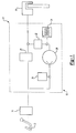
- a vehicular brake system according to this invention is indicated generally at 10 in Figure 1.
- System 10 includes control valves and other components described below to provide anti-lock braking functions.
- system 10 can also include components to provide traction control functions and/or vehicle stability control functions.
- a brake pedal 12 is connected to a master cylinder 14 to provide pressurized brake fluid to a wheel brake 16.
- the wheel brake 16 is illustrated as a disc assembly; however, wheel brake 16 may be any type found on vehicles.
- a hydraulic control unit (HCU) 18 is a housing having bores for receiving control valves and other components described below. Fluid passageways or conduits are provided between the bores to provide fluid communication between the control valves and other components. For purposes of clarity of illustration, only one set of components is illustrated in the schematic of Figure 1. However, it is understood that the HCU 18 can also house corresponding components for other circuits and/or wheels of the vehicle.
- the HCU 18 includes a normally open control valve 20 commonly referred to as an isolation valve, and a normally closed control valve 22, commonly known as a dump valve, disposed between the master cylinder 14 and the wheel brake 16.
- a low pressure accumulator 24 is disposed between the dump valve 22 and a reciprocating hydraulic pump 26.
- the pump 26 is driven by an electric motor (not illustrated).
- An attenuator 28 is provided in the HCU 18 between an outlet of the pump 26 and an inlet of the isolation valve 20. The attenuator 28 dampens fluid pulses exiting the pump 26.
- Both the isolation valve 20 and the dump valve 22 are preferably formed as a solenoid valve switchable between two positions. Valves 20 and 22, as well as pump 26, are electrically connected to an electronic control module (not illustrated) and operated to provide anti-lock or other types of controlled braking as required.
- the isolation valve mechanism In contrast, during a controlled braking event such as an ABS event, the isolation valve mechanism must hold the valve in a partially open state. During a controlled braking event, Bernoulli forces advantageously hold the valve partially open, decreasing demand on the coil.
- FIG. 2 illustrates an isolation valve 20.
- the isolation valve 20 has a cylindrical valve body 100 having a radial flange 102.
- the valve body 100 has a coaxial flow passage 104 provided therethrough which terminates at its upper end in a conical valve seat 106.
- the lower end of the valve body 100 has a reduced diameter portion 108 which has an annular catch 110 adjacent to its lower end.
- a filter assembly 112 having a filter 114 is received over the reduced diameter portion 108 of the valve body 100.
- the filter assembly 112 has an internal recess 116 in which the annular catch 110 is received to snap lock the filter assembly 112 to the end of the valve body 100 so that the filter 114 covers the lower end of the coaxial flow passage 104.
- a cylindrical sleeve 120 has an open lower end and a closed upper end 122.
- the open end is laser welded to the valve body 100 providing a fluid tight seal therebetween.
- the valve body 100 has a reduced diameter section 118 over which the open end of the sleeve 120 is received.
- An armature 124 is slidably disposed in the sleeve 120.
- the armature 124 has an annular flange 126 and an axial bore 128 in which is received a valve member sized to engage the valve seat 106 and block the upper end of the coaxial flow passage 104.
- the valve member is preferably a ball 130.
- the ball 130 is substantially non-deformable, for example, a steel ball.
- a coil spring 132 is disposed between the upper end of the valve body 100 and the flange 126 and resiliently biases the armature 124 away from the valve body 100 and the ball 130 away from the valve seat 106.
- the armature 124 and the flange 126 have through slots 127 providing a fluid passageway between the flange 126 and the closed end 122 of the cylindrical sleeve 100.
- the slots 127 prevent a fluid lock-up condition inhibiting the rapid displacement of the armature 124 relative to the valve body 100.
- a coil assembly such as coil assembly 40 shown in Figure 2 is slideably received over the cylindrical sleeve 120 with a flux ring 164 being in close fitting, sliding engagement with valve body section 118.
- a slight clearance can be allowed between the flux ring 164 and sleeve 120.
- the coil assembly 40 is operative, when energized, to produce a magnetic field displacing the armature 124 towards the valve body 100 causing the ball 130 to seat on the valve seat 106.
- the seating of the ball 130 on the valve seat 106 terminates the fluid flow between the axial fluid inlet passage 104 and an outlet passageway 134 formed in the valve body housing 30 through internal passageways 136 formed in the valve body 100.
- the outlet fluid passageway 134 is connected to an associated threaded aperture and to the input of the associated hold/dump valve 22 as shown in Figure 1.
- the coil assembly 40 includes an annular flux ring 164 disposed at the end adjacent the valve body housing 30.
- the flux ring 164 (as described in greater detail in commonly assigned U.S. Patent No. 5,439,279, the disclosure of which is specifically incorporated by reference) enhances the strength of the magnetic field acting on the armature 124 and reduces the current required to produce a magnetic field having a strength sufficient to displace the armature 124 against the force of spring 132.
- the valve body 100 further has an annular groove 138 in which is received a one-way seal 140 to prevent a fluid flow from the internal inlet passageway 142 of the valve body housing 30 to the outlet passageway 134.
- the internal inlet passageway 142 connects to an associated threaded aperture and to the master brake cylinder 16 and to the output of pump 26 as shown in Figure 1.
- armature 124 such an edge groove 31 as illustrated in Figure 2
- modify fluid flow in order to reduce Bernoulli forces during normal braking events, thereby improving response time and decreasing the required stopping distance.
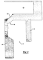
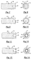
- Figures 3-6 illustrate computational fluid dynamic (CFD) analysis models of isolation valves that lack a variation in the terminal end of the armature and that have an edge groove 31 in the terminal end of the armature.
- the components illustrated in Figures 3-6, except for the armatures in Figures 3 and 5, are identical in form and operation to the components of the isolation valve of Figure 2 and are identified with corresponding numbers.
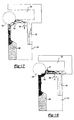
- Figure 3 illustrates a simulation of an embodiment of the invention where the armature 124 has a ball 130 as the valve member fitting in a valve seat 106.
- the armature 124 is modeled in a normally open position permitting fluid communication between the coaxial flow passage 104 and the internal passageway 136.
- a Bernoulli closing force of 3.70 Newton tended to move the armature toward a closed position. Overcoming this force required additional time, affecting the overall stopping power of the hydraulic braking system.
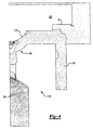
- Figure 4 illustrates a simulation of an embodiment of the invention where the armature 124 has been configured with an edge groove 31 (c.f. Figure 2). Like Figure 3, the armature 124 of Figure 4 is normally open as shown in Figure 3, permitting fluid communication between the coaxial flow passage 104 and the internal passageway 136. The detailed structure of an actual armature 124 having an edge groove is shown in cross-sectional side and end views in Figures 7 and 8.
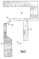
- Figure 5 illustrates a simulation of the same armature shown in Figure 3 in a partially open position as occurs during a controlled braking event.
- a controlled braking event such as an ABS event
- a Bernoulli closing force 4.66 Newton.
- Figure 6 illustrates a simulation of an embodiment of the invention where the armature 124 has been configured with an edge groove 31 (c.f. Figure 2).
- edge groove 31 c.f. Figure 2.
- Bernoulli force generated when the isolation valve is partially open is not eliminated.
- the presence of the edge groove 31 did not significantly change the beneficial effect derived from Bernoulli force during controlled braking events.
- the isolation valve without the edge groove exhibits 3.7 N Bernoulli (closing) force during a normal or base braking event when the valve is fully opened to a 0.6 mm gap.
- the isolation valve with the edge groove 31 exhibits a 0.3 N Bernoulli (opening) force when the valve is fully opened to a 0.6 mm gap.
- the isolation valve without the edge groove exhibits 4.66 N Bernoulli (closing) force when the valve is partially opened to a 0.1 mm gap.
- the desirable Bernoulli force generated is not significantly changed by the edge groove during a controlled braking event. Rather, the isolation valve with the edge groove 31 exhibits 4.32 N Bernoulli (closing) force when the valve is opened to a 0.1 mm gap.
- Figures 9-14 illustrate additional configurations of the armature that reduce Bernoulli force in the desired manner during normal breaking events and without significantly changing the Bernoulli force generated during a controlled braking event in a manner analogous to that described above with reference to an armature having an edge groove.
- Figures 9 and 10 are cross-sectional side and end views of an armature having an outer step 32, an armature 124, flange 126, axial grooves 127, and an axial bore 128;
- Figures 11 and 12 are cross-sectional side and end views of an armature having an annular cavity 33, an armature 124, flange 126, axial grooves 127, and an axial bore 128;
- Figures 13 and 14 are cross-sectional side and end views of an armature having an outer step 32 and an annular cavity 33, an armature 124, flange 126, axial grooves 127, and an axial bore 128.
- Figures 15-18 illustrate additional computational fluid dynamic (CFD) analysis models of isolation valves according to this invention.
- Figure 15 illustrates an embodiment where the armature 124 does not have an end groove or other configuration.
- the armature 124 is illustrated in the normally open position.
- the jet direction of the fluid is indicated at arrow 150 and is substantially parallel to the planar lower surface of the armature 124 as it travels from passage 104 to passageway 136.
- a relatively large Bernoulli closing force (approximately 3.70 Newtons) indicated by arrow 152 tended to move the armature 124 to the closed position.
- Figure 16 illustrates an embodiment of the armature wherein an end groove near the ball 130 is formed in the armature 124.
- the end groove can be similar to annular cavity 33 shown in Figures 13 and 14.
- the armature 124 is normally open, permitting fluid communication between passage 104 and passageway 136.
- the jet direction of the fluid is indicated at arrow 154 and is inclined downwardly away from the lower surface of the armature 124.
- a relatively large Bernoulli opening force (approximately 7.10 Newtons) indicated by arrow 156 tended to open the armature 124. This opening force 156 replaces the closing force 152 found in the isolation valve without the cavity 33.
- Figure 17 illustrates the same armature as in Figure 15 in a partially open position as occurs during a controlled braking event.
- a Bernoulli closing force (approximately 4.10 Newtons) indicated by arrow 160 was generated.
- Arrow 162 extending toward passage 136 indicates the jet direction.
- Figure 18 illustrates the same armature as in Figure 16 in a partially open position as occurs during a controlled braking event.
- a beneficial Bernoulli closing force (approximately 3.10 Newtons) indicated by arrow 164.
- the jet direction is indicated by arrow 166 extending toward passage 136 and bypassing groove 33.
- an end groove 33 or configuration in the end surface of the armature adjacent the ball 130 improves a closing force for base braking applications without significantly impacting a closing force for ABS events. This design reduces noise and vibration occurring from the isolation valve.
- the specific size of the groove 33 can be varied to produce desired results.
- Another aspect of the present invention is a method of manufacturing an isolation valve for use in a hydraulic control unit for a vehicular brake system.
- This method comprising the following steps: forming a valve cavity in a valve body housing; mounting a valve stem in the valve cavity where the valve stem has a coaxial fluid passage therethrough; mounting a cylindrical sleeve on the valve body surrounding the valve stem; forming an armature having a valve end for controlling fluid flow through the coaxial fluid passage; configuring the valve end to modify Bernoulli force that affects movement of the armature; and mounting the configured armature in the cylindrical sleeve so that it is slideable and biased by a spring in a normally open position.
- the valve cavity may be formed in the valve body and valve stem housing using any convenient method such as boring or casting.
- the armature may be cast and configured using standard machining methods.
- the armature might be formed in the desired configuration using Metal Injection Molding (MIM) or a similar method.
- MIM Metal Injection Molding
- the configuration of the valve end used to modify the Bernoulli force may be any of the configurations described herein (such as an edge groove, an outer step, or an annular cavity), or combinations of configurations (such as an outer step and an annular cavity). While the present invention has been described as used in specific embodiments of an isolation valve, it is understood that modifications to any control valve armature as described herein to reduce Bernoulli forces and increase response time is within the scope of the present invention.
Landscapes
- Physics & Mathematics (AREA)
- Engineering & Computer Science (AREA)
- Fluid Mechanics (AREA)
- Transportation (AREA)
- Mechanical Engineering (AREA)
- Electromagnetism (AREA)
- Magnetically Actuated Valves (AREA)
- Regulating Braking Force (AREA)
- Valves And Accessory Devices For Braking Systems (AREA)
- Lift Valve (AREA)
Applications Claiming Priority (2)
| Application Number | Priority Date | Filing Date | Title |
|---|---|---|---|
| US340942 | 1989-04-20 | ||
| US09/340,492 US6471305B1 (en) | 1999-06-30 | 1999-06-30 | Isolation valve armature configured to reduce bernoulli force during normal braking operation |
Publications (3)
| Publication Number | Publication Date |
|---|---|
| EP1065116A2 true EP1065116A2 (fr) | 2001-01-03 |
| EP1065116A3 EP1065116A3 (fr) | 2003-04-16 |
| EP1065116B1 EP1065116B1 (fr) | 2005-02-09 |
Family
ID=23333583
Family Applications (1)
| Application Number | Title | Priority Date | Filing Date |
|---|---|---|---|
| EP00113921A Expired - Lifetime EP1065116B1 (fr) | 1999-06-30 | 2000-06-30 | Armature de valve d'isolement configurée pour réduire les forces de Bernoulli pendant des freinages normaux |
Country Status (4)
| Country | Link |
|---|---|
| US (1) | US6471305B1 (fr) |
| EP (1) | EP1065116B1 (fr) |
| JP (1) | JP2001055132A (fr) |
| DE (1) | DE60017981T2 (fr) |
Cited By (5)
| Publication number | Priority date | Publication date | Assignee | Title |
|---|---|---|---|---|
| KR100423646B1 (ko) * | 2000-07-18 | 2004-03-22 | 주식회사 만도 | 안티록 브레이크 시스템용 노말 오픈형 솔레노이드밸브 |
| WO2006026503A1 (fr) * | 2004-08-27 | 2006-03-09 | Kelsey-Hayes Company | Électrovalve à armature sphérique |
| US7341320B2 (en) | 2003-05-19 | 2008-03-11 | Hitachi, Ltd. | Electromagnetically actuated valve |
| WO2008043623A1 (fr) * | 2006-10-10 | 2008-04-17 | Robert Bosch Gmbh | Électrovanne |
| WO2012107137A1 (fr) * | 2011-02-08 | 2012-08-16 | Robert Bosch Gmbh | Électrovanne de commande d'un fluide |
Families Citing this family (17)
| Publication number | Priority date | Publication date | Assignee | Title |
|---|---|---|---|---|
| JP2002323162A (ja) * | 2001-04-26 | 2002-11-08 | Sumitomo Denko Brake Systems Kk | 電磁弁 |
| KR100466952B1 (ko) * | 2002-04-24 | 2005-01-24 | 현대모비스 주식회사 | 안티로크 브레이크 액압 제어용 밸브 |
| KR100465811B1 (ko) * | 2002-04-24 | 2005-01-13 | 현대모비스 주식회사 | 안티로크 브레이크 시스템의 액압 제어용 밸브 |
| KR100465201B1 (ko) * | 2002-07-16 | 2005-01-13 | 현대모비스 주식회사 | 안티로크 브레이크 시스템의 액압 제어용 전자식 밸브 |
| DE102004001565A1 (de) * | 2004-01-10 | 2005-08-04 | Robert Bosch Gmbh | Elektromagnetisches Ventil, insbesondere für eine Bremsanlage eines Kraftfahrzeugs |
| DE102004030428A1 (de) * | 2004-06-24 | 2006-01-19 | Robert Bosch Gmbh | Ventilvorrichtung |
| US7367636B2 (en) * | 2005-02-16 | 2008-05-06 | Bendix Commercial Vehicle Systems, Llc | Solenoid armature with integrated spherical soft seal |
| DE102006047917A1 (de) * | 2006-10-10 | 2008-04-17 | Robert Bosch Gmbh | Ventilkörper und zugehöriges Magnetventil |
| KR100839715B1 (ko) * | 2007-05-02 | 2008-06-19 | 현대모비스 주식회사 | 측면 유로 입구 타입 솔레노이드 밸브 |
| US8192172B2 (en) * | 2009-04-06 | 2012-06-05 | Woodward, Inc. | Flow sensing shutoff valve |
| DE102009019534A1 (de) * | 2009-04-30 | 2010-12-02 | Schaeffler Technologies Gmbh & Co. Kg | Elektromagnetisches Hydraulikventil |
| KR101198752B1 (ko) | 2010-09-16 | 2012-11-12 | 주식회사 만도 | 브레이크 시스템용 솔레노이드 밸브 |
| KR101198751B1 (ko) | 2010-09-20 | 2012-11-12 | 주식회사 만도 | 안티록 브레이크 시스템용 솔레노이드 밸브 |
| KR101617802B1 (ko) * | 2014-10-30 | 2016-05-03 | 현대모비스 주식회사 | 감압 솔레노이드 밸브 |
| US10544770B2 (en) | 2017-06-29 | 2020-01-28 | Woodward, Inc. | Mecha-hydraulic actuated inlet control valve |
| DE102018201883A1 (de) * | 2018-02-07 | 2019-08-08 | Continental Teves Ag & Co. Ohg | Elektromagnetventil, insbesondere für hydraulische Kraftfahrzeugbremsanlagen |
| JP7103066B2 (ja) * | 2018-08-28 | 2022-07-20 | 浜名湖電装株式会社 | 流体制御弁 |
Family Cites Families (31)
| Publication number | Priority date | Publication date | Assignee | Title |
|---|---|---|---|---|
| DE2113001B1 (de) * | 1971-03-18 | 1972-02-03 | Westinghouse Bremsen Und Appba | Elektromagnetisch betaetigtes Entlueftungsventil mit hoher Beschleunigung |
| DE2134067A1 (de) * | 1971-07-08 | 1973-01-25 | Servo Technik Gmbh | Elektromagnetisches ventil |
| GB1433445A (en) * | 1973-06-05 | 1976-04-28 | Rau Swf Autozubehoer | Magnetic valve |
| US4021152A (en) | 1974-12-06 | 1977-05-03 | Taisan Industrial Co., Ltd. | Electromagnetic pump |
| US4791958A (en) | 1983-12-21 | 1988-12-20 | Brundage Robert W | Solenoid controlled fluid valve |
| US4531708A (en) * | 1984-08-21 | 1985-07-30 | Honeywell Lucifer Sa | Solenoid valve |
| US4865399A (en) * | 1985-08-09 | 1989-09-12 | Kelsey Hayes Company | Vehicle anti-lock brake system |
| US4668023A (en) * | 1985-08-09 | 1987-05-26 | Kelsey-Hayes Company | Control valve for an anti-lock brake system |
| DE3534665A1 (de) * | 1985-09-28 | 1987-04-09 | Bosch Gmbh Robert | Zweistellungs-magnetventil |
| KR930006510B1 (ko) * | 1988-07-29 | 1993-07-16 | 미쓰비시전기 주식회사 | 전자밸브 |
| US5011113A (en) * | 1988-12-29 | 1991-04-30 | Applied Power Inc. | Fluid control valve |
| US4941447A (en) * | 1989-02-21 | 1990-07-17 | Colt Industries Inc. | Metering valve |
| US5253676A (en) * | 1992-08-13 | 1993-10-19 | Moog Controls, Inc. | Low Bernoulli force control orifice |
| JP2569208Y2 (ja) * | 1992-10-13 | 1998-04-22 | 株式会社ユニシアジェックス | 電磁弁構造 |
| JP3294382B2 (ja) * | 1992-10-30 | 2002-06-24 | 株式会社デンソー | 流量制御弁 |
| DE4324533C2 (de) | 1993-07-21 | 1996-04-25 | Lucas Ind Plc | Ventilanordnung |
| DE4332372A1 (de) | 1993-09-23 | 1995-03-30 | Bosch Gmbh Robert | Elektromagnetisch betätigbares Ventil, insbesondere für schlupfgeregelte hydraulische Bremsanlagen in Kraftfahrzeugen |
| US5439279A (en) * | 1994-02-18 | 1995-08-08 | Kelsey-Hayes Company | Vehicular anti-lock brake system hydraulic control unit |
| US5791747A (en) * | 1994-02-18 | 1998-08-11 | Kelsey-Hayes Company | Hydraulic valve control unit for vehicular anti-lock brake and traction control systems |
| US5364067A (en) | 1994-02-18 | 1994-11-15 | Kelsey-Hayes Corporation | Vehicular anti-lock brake system hydraulic control valve and method of making same |
| DE19530899C2 (de) * | 1995-08-23 | 2003-08-21 | Bosch Gmbh Robert | Magnetventil, insbesondere für eine schlupfgeregelte, hydraulische Bremsanlage für Kraftfahrzeuge |
| US6026847A (en) | 1995-10-11 | 2000-02-22 | Reinicke; Robert H. | Magnetostrictively actuated valve |
| DE19604315A1 (de) | 1996-02-07 | 1997-08-14 | Bosch Gmbh Robert | Elektromagnetisch betätigtes Ventil, insbesondere für hydraulische Bremsanlagen von Kraftfahrzeugen |
| DE19604317A1 (de) * | 1996-02-07 | 1997-08-14 | Bosch Gmbh Robert | Elektromagnetisch betätigtes Ventil, insbesondere für hydraulische Bremsanlagen von Kraftfahrzeugen |
| US5887621A (en) * | 1996-04-10 | 1999-03-30 | Applied Power Inc. | On/off bidirectional valve |
| DE19649225A1 (de) | 1996-11-27 | 1998-05-28 | Nass Magnet Gmbh | Ventil |
| EP0966379A1 (fr) * | 1997-03-11 | 1999-12-29 | Kelsey-Hayes Company | Sous-ensemble armature et manchon pour soupapes de commande du systeme de freinage d'un vehicule, et leur procede de fabrication |
| US5791339A (en) | 1997-03-13 | 1998-08-11 | Nellcor Puritan Bennettt Incorprated | Spring piloted safety valve with jet venturi bias |
| US6065734A (en) | 1997-10-03 | 2000-05-23 | Kelsey-Hayes Company | Control valve for a hydraulic control unit of vehicular brake systems |
| US6029703A (en) | 1998-12-18 | 2000-02-29 | Borg-Warner Automotive, Inc. | Pressure solenoid control valve with flux shunt |
| US6065495A (en) | 1999-02-04 | 2000-05-23 | General Motors Corporation | Two-position, three-way solenoid-actuated valve |
-
1999
- 1999-06-30 US US09/340,492 patent/US6471305B1/en not_active Expired - Fee Related
-
2000
- 2000-06-29 JP JP2000195470A patent/JP2001055132A/ja active Pending
- 2000-06-30 DE DE60017981T patent/DE60017981T2/de not_active Expired - Fee Related
- 2000-06-30 EP EP00113921A patent/EP1065116B1/fr not_active Expired - Lifetime
Cited By (8)
| Publication number | Priority date | Publication date | Assignee | Title |
|---|---|---|---|---|
| KR100423646B1 (ko) * | 2000-07-18 | 2004-03-22 | 주식회사 만도 | 안티록 브레이크 시스템용 노말 오픈형 솔레노이드밸브 |
| US7341320B2 (en) | 2003-05-19 | 2008-03-11 | Hitachi, Ltd. | Electromagnetically actuated valve |
| DE102004024673B4 (de) * | 2003-05-19 | 2012-01-12 | Hitachi, Ltd. | Elektromagnetisch betätigtes Ventil |
| WO2006026503A1 (fr) * | 2004-08-27 | 2006-03-09 | Kelsey-Hayes Company | Électrovalve à armature sphérique |
| US7195226B2 (en) | 2004-08-27 | 2007-03-27 | Kelsey-Hayes Company | Solenoid valve with spherical armature |
| WO2008043623A1 (fr) * | 2006-10-10 | 2008-04-17 | Robert Bosch Gmbh | Électrovanne |
| WO2012107137A1 (fr) * | 2011-02-08 | 2012-08-16 | Robert Bosch Gmbh | Électrovanne de commande d'un fluide |
| US9133957B2 (en) | 2011-02-08 | 2015-09-15 | Robert Bosch Gmbh | Magnet valve for controlling a fluid |
Also Published As
| Publication number | Publication date |
|---|---|
| EP1065116A3 (fr) | 2003-04-16 |
| DE60017981T2 (de) | 2006-04-06 |
| EP1065116B1 (fr) | 2005-02-09 |
| JP2001055132A (ja) | 2001-02-27 |
| DE60017981D1 (de) | 2005-03-17 |
| US6471305B1 (en) | 2002-10-29 |
Similar Documents
| Publication | Publication Date | Title |
|---|---|---|
| EP1065116B1 (fr) | Armature de valve d'isolement configurée pour réduire les forces de Bernoulli pendant des freinages normaux | |
| EP0997363B1 (fr) | Soupape pilote pour unité de commande hydraulique d'un système de freinage pour véhicules | |
| US5865213A (en) | Controllable valve | |
| KR100495961B1 (ko) | 전자밸브 | |
| JP3365151B2 (ja) | 電磁弁 | |
| US7396090B2 (en) | EHB proportional solenoid valve with stepped gap armature | |
| US5971501A (en) | Pressure control valve unit for hydraulic brake device | |
| JP3786477B2 (ja) | 自動車の特にスリップ制御式油圧ブレーキ装置用の電磁弁 | |
| CN112747124B (zh) | 两级电磁阀 | |
| CN109843665B (zh) | 电磁阀和用于车辆的液压制动系统 | |
| US5167441A (en) | Anti-lock brake system for automotive vehicles | |
| US5681097A (en) | Hydraulic control unit for vehicular anti-lock brake and traction control systems | |
| US20120248357A1 (en) | Solenoid valve for brake system | |
| JP2002509839A (ja) | 電磁バルブ | |
| US5730509A (en) | Magnetic control valve for a slip-controlled hydraulic brake system for motor vehicles | |
| US6302499B1 (en) | Control valve for a hydraulic control unit of vehicular brake systems | |
| US6450590B1 (en) | Control valve with reduced seat for a hydraulic control unit | |
| JP3773146B2 (ja) | 液圧制御弁装置 | |
| GB2284877A (en) | Electromagnetically operated valve | |
| JP3631904B2 (ja) | 電磁弁 | |
| KR100553657B1 (ko) | 전자석 밸브 장치 | |
| US5251969A (en) | Brake power controller with electrically actuated locking apparatus | |
| US6332655B1 (en) | Electromagnetic valve for a hydraulic brake | |
| JPH05246320A (ja) | 油圧式のブレーキ装置 | |
| KR20010042092A (ko) | 전자기밸브 |
Legal Events
| Date | Code | Title | Description |
|---|---|---|---|
| PUAI | Public reference made under article 153(3) epc to a published international application that has entered the european phase |
Free format text: ORIGINAL CODE: 0009012 |
|
| AK | Designated contracting states |
Kind code of ref document: A2 Designated state(s): AT BE CH CY DE DK ES FI FR GB GR IE IT LI LU MC NL PT SE |
|
| AX | Request for extension of the european patent |
Free format text: AL;LT;LV;MK;RO;SI |
|
| PUAL | Search report despatched |
Free format text: ORIGINAL CODE: 0009013 |
|
| AK | Designated contracting states |
Designated state(s): AT BE CH CY DE DK ES FI FR GB GR IE IT LI LU MC NL PT SE |
|
| AX | Request for extension of the european patent |
Extension state: AL LT LV MK RO SI |
|
| 17P | Request for examination filed |
Effective date: 20030527 |
|
| 17Q | First examination report despatched |
Effective date: 20030709 |
|
| AKX | Designation fees paid |
Designated state(s): DE ES FR GB IT |
|
| GRAP | Despatch of communication of intention to grant a patent |
Free format text: ORIGINAL CODE: EPIDOSNIGR1 |
|
| GRAS | Grant fee paid |
Free format text: ORIGINAL CODE: EPIDOSNIGR3 |
|
| GRAA | (expected) grant |
Free format text: ORIGINAL CODE: 0009210 |
|
| AK | Designated contracting states |
Kind code of ref document: B1 Designated state(s): DE ES FR GB IT |
|
| PG25 | Lapsed in a contracting state [announced via postgrant information from national office to epo] |
Ref country code: FR Free format text: LAPSE BECAUSE OF NON-PAYMENT OF DUE FEES Effective date: 20050209 Ref country code: ES Free format text: LAPSE BECAUSE OF FAILURE TO SUBMIT A TRANSLATION OF THE DESCRIPTION OR TO PAY THE FEE WITHIN THE PRESCRIBED TIME-LIMIT Effective date: 20050209 Ref country code: IT Free format text: LAPSE BECAUSE OF FAILURE TO SUBMIT A TRANSLATION OF THE DESCRIPTION OR TO PAY THE FEE WITHIN THE PRESCRIBED TIME-LIMIT;WARNING: LAPSES OF ITALIAN PATENTS WITH EFFECTIVE DATE BEFORE 2007 MAY HAVE OCCURRED AT ANY TIME BEFORE 2007. THE CORRECT EFFECTIVE DATE MAY BE DIFFERENT FROM THE ONE RECORDED. Effective date: 20050209 |
|
| REG | Reference to a national code |
Ref country code: GB Ref legal event code: FG4D |
|
| REG | Reference to a national code |
Ref country code: IE Ref legal event code: FG4D |
|
| REF | Corresponds to: |
Ref document number: 60017981 Country of ref document: DE Date of ref document: 20050317 Kind code of ref document: P |
|
| PG25 | Lapsed in a contracting state [announced via postgrant information from national office to epo] |
Ref country code: GB Free format text: LAPSE BECAUSE OF NON-PAYMENT OF DUE FEES Effective date: 20050630 |
|
| PLBE | No opposition filed within time limit |
Free format text: ORIGINAL CODE: 0009261 |
|
| STAA | Information on the status of an ep patent application or granted ep patent |
Free format text: STATUS: NO OPPOSITION FILED WITHIN TIME LIMIT |
|
| 26N | No opposition filed |
Effective date: 20051110 |
|
| GBPC | Gb: european patent ceased through non-payment of renewal fee |
Effective date: 20050630 |
|
| EN | Fr: translation not filed | ||
| PGFP | Annual fee paid to national office [announced via postgrant information from national office to epo] |
Ref country code: DE Payment date: 20090626 Year of fee payment: 10 |
|
| PG25 | Lapsed in a contracting state [announced via postgrant information from national office to epo] |
Ref country code: DE Free format text: LAPSE BECAUSE OF NON-PAYMENT OF DUE FEES Effective date: 20110101 |