EP1065122B1 - Essieu de roue folle pour véhicules ferroviaires - Google Patents
Essieu de roue folle pour véhicules ferroviaires Download PDFInfo
- Publication number
- EP1065122B1 EP1065122B1 EP00111850A EP00111850A EP1065122B1 EP 1065122 B1 EP1065122 B1 EP 1065122B1 EP 00111850 A EP00111850 A EP 00111850A EP 00111850 A EP00111850 A EP 00111850A EP 1065122 B1 EP1065122 B1 EP 1065122B1
- Authority
- EP
- European Patent Office
- Prior art keywords
- wheel
- shaft
- loose
- wheel axle
- axle according
- Prior art date
- Legal status (The legal status is an assumption and is not a legal conclusion. Google has not performed a legal analysis and makes no representation as to the accuracy of the status listed.)
- Expired - Lifetime
Links
Images

Classifications
-
- B—PERFORMING OPERATIONS; TRANSPORTING
- B61—RAILWAYS
- B61F—RAIL VEHICLE SUSPENSIONS, e.g. UNDERFRAMES, BOGIES OR ARRANGEMENTS OF WHEEL AXLES; RAIL VEHICLES FOR USE ON TRACKS OF DIFFERENT WIDTH; PREVENTING DERAILING OF RAIL VEHICLES; WHEEL GUARDS, OBSTRUCTION REMOVERS OR THE LIKE FOR RAIL VEHICLES
- B61F3/00—Types of bogies
- B61F3/16—Types of bogies with a separate axle for each wheel
-
- B—PERFORMING OPERATIONS; TRANSPORTING
- B61—RAILWAYS
- B61C—LOCOMOTIVES; MOTOR RAILCARS
- B61C9/00—Locomotives or motor railcars characterised by the type of transmission system used; Transmission systems specially adapted for locomotives or motor railcars
- B61C9/38—Transmission systems in or for locomotives or motor railcars with electric motor propulsion
- B61C9/52—Transmission systems in or for locomotives or motor railcars with electric motor propulsion with transmission shafts at an angle to the driving axles
-
- B—PERFORMING OPERATIONS; TRANSPORTING
- B61—RAILWAYS
- B61F—RAIL VEHICLE SUSPENSIONS, e.g. UNDERFRAMES, BOGIES OR ARRANGEMENTS OF WHEEL AXLES; RAIL VEHICLES FOR USE ON TRACKS OF DIFFERENT WIDTH; PREVENTING DERAILING OF RAIL VEHICLES; WHEEL GUARDS, OBSTRUCTION REMOVERS OR THE LIKE FOR RAIL VEHICLES
- B61F15/00—Axle-boxes
- B61F15/20—Details
- B61F15/28—Axle-boxes modified to ensure electrical conductivity
-
- B—PERFORMING OPERATIONS; TRANSPORTING
- B61—RAILWAYS
- B61F—RAIL VEHICLE SUSPENSIONS, e.g. UNDERFRAMES, BOGIES OR ARRANGEMENTS OF WHEEL AXLES; RAIL VEHICLES FOR USE ON TRACKS OF DIFFERENT WIDTH; PREVENTING DERAILING OF RAIL VEHICLES; WHEEL GUARDS, OBSTRUCTION REMOVERS OR THE LIKE FOR RAIL VEHICLES
- B61F3/00—Types of bogies
- B61F3/02—Types of bogies with more than one axle
- B61F3/04—Types of bogies with more than one axle with driven axles or wheels
Definitions
- the present invention relates to a Losradachse with individually mounted wheels for single or double axle chassis rail vehicles, in particular low-floor vehicles, with a U-shaped, the wheels with lateral Support legs outside encompassing Radtragrahmen, wherein each wheel on the inside of the associated support leg via a wheel bearing arranged inside the wheel a stub axle of the support leg is rotatably hinged, and wherein each wheel is torque-locked on its inside connected to a shaft extending through openings of the wheel and the support leg extends to the outside.
- Such a loose wheel axle is described in WO 98/24674. It is concretely a driven axle, being on each chassis longitudinal outside of the chassis frame a drive is fastened. The drive is - due to a between the support frame and a Drive-carrying chassis frame provided primary suspension - via a gimbal double clutch with the wheel connected.
- a first, drive-side coupling plane arranged on the outside of the drive and a second, output-side clutch plane is located directly on the Inside of the wheel.
- the thus acting as a propeller shaft Wave runs consistently with appropriate length between the two coupling planes of the gimbal Double coupling.
- This known Losradachse has the advantage that axis and drive can have a small width, for example, even narrow-gauge vehicles with at the same time small car body width without disturbing projection of the To allow landing gear.
- Another advantage exists in that the bearing of the wheel within it is arranged, whereby a good load capacity and high Lifespan is reached.
- this solution is then of Disadvantage if a maximum, only by the distance the wheels and necessary transverse suspension paths and clearances Limited aisle width (such as in low-floor wagons usual), as this is due to the inside the wheel arranged coupling plane is limited.
- the disadvantage can also be hampered by the coupling plane Accessibility of wheel components, such. B. the Wheel bearing, for maintenance work.
- should an adaptation to other z. B. even lower gauges virtually the entire design can be changed.
- the present invention is based on the object, a Losradachse of the generic type to create with the a particularly good application variability, in particular in terms of adaptation to lower gauges achieved while maintaining the benefit of one optimal design of the wheel bearing by arranging the same inside the wheel. In addition, maintenance work be relieved.
- the shaft as a brake shaft can be used by putting in the Coupling level is connected to a braking device.
- the braking device is advantageous as a disc brake executed, with the brake shaft, a brake disc is connected, which supported with a support leg Brake caliper interacts.
- the invention also includes maintenance and repair work fast and easy to carry out, because all Components are easily accessible. This is especially true for the wheel bearing, which is almost free from the frame inside is accessible, and advantageously without disassembly of the drive.
- the drive itself can be simple and fast be separated from the intermediate shaft according to the invention, without causing the frame-mounted part dismantled would have to be (wheel with intermediate shaft).
- One in case of one electrical drive required grounding contact arrangement is preferred on the outside, d. H. leading the way from the wheel End of the shaft according to the invention arranged integrated in this.
- the ground contact arrangement can also be good through the hollow drive shaft through from the vehicle outside be achieved.
- Fig. 1 is initially an example of an application of two erf indungsdorfen Losradachsen 1 in a driven Double axle landing gear illustrated.
- a drive unit 2 negotiate, the from an electric motor 4 and flanged on both sides Bevel gearboxes 6 consists.
- Each axis has a U-shaped Wheel frame 8 on, also under the term Portal axis is known.
- wheels 10 stored individually, the wheel support frame 8, the wheels with lateral support legs 12 engages around the outside and each Wheel 10 on the inside of the associated support leg 12th is hinged.
- Each drive unit 2 is at one suspension frame not shown suspended via a primary suspension on the respective wheel frame 8 is supported.
- the wheel support frame 8 in particular in Area of the support legs 12 bearing surfaces 14 for primary spring elements on.
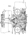
- each wheel 10 is on its Inside torque-tight connected to a shaft 16, extending through openings of the wheel 10 and the Carrying leg 12 extends to the outside.
- This shaft 16 ends According to the invention in a directly on the outside of the Carrying leg 12 formed coupling plane 18th
- the shaft 16 is on its inside over a detachable connection element 30 rigidly connected to the wheel 10, so that the shaft rotates coaxially with the wheel.
- the wheel 10 itself is about a wheel bearing 32 on a in the wheel 10th engaging axle stub 34 of the support leg 12 stored. This embodiment ensures optimal bearing stress and thereby a long shelf life of the bearings.
- the Shaft 16 can - as shown - additionally via a pivot bearing 36 be stored in the support leg 12.
- the shaft 16 forms a drive intermediate shaft 20, in the coupling plane 18 via a Clutch 22 with an actual drive shaft 24 of the Drive unit 2 is connected.
- the drive shaft 24 is on its other, opposite side over one another clutch 26 with the gear 6 of the drive. 2 connected.
- the Drive shaft 24 as an extension of the intermediate shaft essentially coaxial, preferably hollow cardan shaft and the two two-sided couplings 22 and 26 as gimbals Double clutch executed.
- the drive shaft runs 24 through the gear 6 through, so that a Drive-side coupling plane 28 on the support frame of the 8th technological outside of the transmission 6 and the drive 2, while the output-side clutch plane 18 and the clutch 22 between the gear 6 and the support leg 12 of the support frame 8 are (see also Fig. 1).
- Each coupling 22, 26 is made in a conventional manner star-shaped coupling pieces, with the interposition of elastic, wedge-like compensation elements interlock. This allows a gimbal balance of suspension movements of the order of at least approx. ⁇ 15 mm.
- a ground contact arrangement 38 on the shaft 16 on the Side of the coupling plane 18 is arranged integrated. there it is a sliding contact arrangement to a electrically conductive connection between rotating and to ensure non-rotating parts.
- the ground contact arrangement 38 is about a centric, through the hollow trained shaft 16 extending to the inside of the wheel Holding rod 40 and an adjoining, horizontal Torque support 42 fixed to the support frame. 8 supported. It can between the hollow shaft 16 and the Holding rod 40 at least one pivot bearing 44 may be arranged in particular in the interior, approximately in the plane of Rades 10 lying area.
- the idler axle 1 also be used in a non-powered version. It then omitted the drive units 2 with the electric motors 4 and the gears 6 including the drive shafts 24. It can then each wave 16 advantageously as Brake shaft can be used by being in the coupling plane 18 is connected to a braking device. At this not shown alternative is then the braking device preferably designed as a disc brake, wherein with the Shaft 16 is connected to a brake disc, so that these rotates together with the wheel 10. The brake disc acts supported with a support leg 12 of the Radtragrahmens 8 Brake caliper together.
Landscapes
- Engineering & Computer Science (AREA)
- Mechanical Engineering (AREA)
- Chemical & Material Sciences (AREA)
- Combustion & Propulsion (AREA)
- Transportation (AREA)
- Braking Arrangements (AREA)
- Vehicle Body Suspensions (AREA)
- Arrangement And Driving Of Transmission Devices (AREA)
Claims (9)
- Essieu à roues indépendantes (1) comprenant des roues tourillonnées individuellement (10) pour bogies de véhicules ferroviaires à un essieu ou à deux essieux, en particulier de véhicules à plancher surbaissé, comprenant un cadre support de roues (8) qui encadre extérieurement les roues (10) avec des branches porteuses latérales (12), chaque roue (10) étant montée rotative, par l'intermédiaire d'un palier de roue (32) sur un tourillon d'essieu (34) de la branche porteuse (12), sur le côté intérieur de la branche porteuse (12) correspondante, par l'intermédiaire d'un palier de roue (32) disposé à l'intérieur de la roue, et dans lequel, sur son côté intérieur, chaque roue (10) est reliée en liaison de transmission du couple à un arbre (16) qui s'étend vers l'extérieur à travers des ouvertures de la roue (10) et de la branche porteuse (12),
caractérisé en ce que
l'arbre (16) se termine dans un plan d'accouplement (18) formé directement sur le côté extérieur de la branche porteuse (12). - Essieu à roues indépendantes selon la revendication 1,
caractérisé en ce que l'arbre (16) est relié rigidement à la roue (10) au moyen d'un élément de jonction (30) et il est de préférence tourillonné en supplément dans la branche porteuse (12) par l'intermédiaire d'un palier (36). - Essieu à roues indépendantes selon la revendication 1 ou 2,
caractérisé en ce que l'arbre (16) présente, sur le côté du plan d'accouplement (18), un dispositif de contact de mise à la masse intégré (38). - Essieu à roues indépendantes selon la revendication 3,
caractérisé en ce que le dispositif de contact de mise à la masse (38) est supporté en position fixe, par l'intermédiaire d'une barre de maintien centrale (40) qui passe à travers l'arbre (16) de forme creuse jusqu'au côté intérieur de la roue, et d'un appui de réaction de couple (42). - Essieu à roues indépendantes selon la revendication 4,
caractérisé en ce qu'au moins un palier (44) est disposé entre l'arbre creux (16) et la barre de maintien (40.) - Essieu à roues indépendantes selon une des revendications 1 à 5,
caractérisé en ce que l'arbre (16) forme un arbre intermédiaire d'entraínement (20) et est relié, dans le plan d'accouplement (18) et par l'intermédiaire d'un accouplement (22), à un arbre d'entraínement (24) appartenant à un entraínement (2) disposé à l'extérieur sur le côté longitudinal du véhicule ferroviaire. - Essieu à roues indépendantes selon la revendication 6,
caractérisé en ce que l'arbre d'entraínement (24) de constitution creuse présente, sur son côté extérieur qui est orienté dans le sens qui s'éloigne de l'arbre intermédiaire (20), une ouvertures de visite (48) pour le dispositif de contact de mise à la masse (38). - Essieu à roues indépendantes selon une des revendications 1 ou 5,
caractérisé en ce que l'arbre (16) forme un arbre de frein et est relié à un dispositif de frein dans le plan d'accouplement (18). - Essieu à roues indépendantes selon la revendication 8,
caractérisé en ce que le dispositif de frein est réalisé sous la forme d'un frein à disque, dans lequel, à l'arbre de frein, est relié un disque de frein qui coopère avec un étrier de frein qui prend appui sur la branche porteuse (12).
Applications Claiming Priority (2)
| Application Number | Priority Date | Filing Date | Title |
|---|---|---|---|
| DE19930424A DE19930424A1 (de) | 1999-07-01 | 1999-07-01 | Losradachse für Schienenfahrzeuge |
| DE19930424 | 1999-07-01 |
Publications (2)
| Publication Number | Publication Date |
|---|---|
| EP1065122A1 EP1065122A1 (fr) | 2001-01-03 |
| EP1065122B1 true EP1065122B1 (fr) | 2004-02-18 |
Family
ID=7913345
Family Applications (1)
| Application Number | Title | Priority Date | Filing Date |
|---|---|---|---|
| EP00111850A Expired - Lifetime EP1065122B1 (fr) | 1999-07-01 | 2000-06-08 | Essieu de roue folle pour véhicules ferroviaires |
Country Status (4)
| Country | Link |
|---|---|
| EP (1) | EP1065122B1 (fr) |
| AT (1) | ATE259729T1 (fr) |
| DE (2) | DE19930424A1 (fr) |
| ES (1) | ES2213518T3 (fr) |
Cited By (2)
| Publication number | Priority date | Publication date | Assignee | Title |
|---|---|---|---|---|
| EP3712031A1 (fr) * | 2019-03-19 | 2020-09-23 | Bombardier Transportation GmbH | Agencement de roue pour véhicule ferroviaire |
| EP3971051A1 (fr) | 2020-09-16 | 2022-03-23 | Bombardier Transportation GmbH | Agencement de roue pour véhicule ferroviaire |
Families Citing this family (5)
| Publication number | Priority date | Publication date | Assignee | Title |
|---|---|---|---|---|
| DE10122185A1 (de) * | 2001-05-08 | 2002-11-14 | Gutehoffnungshuette Radsatz | Losrad-Anordnung für Schienenfahrzeuge |
| DE20114948U1 (de) | 2001-05-08 | 2001-12-13 | Gutehoffnungshütte Radsatz GmbH, 46145 Oberhausen | Losrad-Anordnung für Schienenfahrzeuge |
| DE102015222125A1 (de) * | 2015-11-10 | 2017-05-11 | Bombardier Transportation Gmbh | Antriebsanordnung für ein Schienenfahrzeug, Schienenfahrzeug mit der Antriebsanordnung und Verfahren zur Herstellung |
| CN105460023B (zh) * | 2015-12-25 | 2017-12-12 | 中车戚墅堰机车车辆工艺研究所有限公司 | 低地板轨道车辆用齿轮箱 |
| IT201600088005A1 (it) * | 2016-08-30 | 2018-03-02 | Lucchini Rs Spa | Ponte-assale di veicoli ferroviari e ferrotranviari a pianale ribassato |
Family Cites Families (6)
| Publication number | Priority date | Publication date | Assignee | Title |
|---|---|---|---|---|
| DE3230453A1 (de) * | 1982-08-16 | 1984-02-16 | Kollektra Metall- und Kunststoff-Werk GmbH, 6301 Wettenberg | Kontaktanordnung zur elektrischen ueberbrueckung der achslager von schienenfahrzeugen |
| DE3931912A1 (de) * | 1989-09-25 | 1991-04-04 | Eickhoff Geb | Einzelradlagerung eines triebrades an schienenfahrzeugen |
| DE59301379D1 (de) * | 1992-04-22 | 1996-02-22 | Sgp Verkehrstechnik | Fahrwerk für Schienenfahrzeuge, insbesondere Niederflurwagen |
| DE4429889A1 (de) | 1994-08-24 | 1996-02-29 | Bergische Stahlindustrie | Angetriebenes Fahrwerk für Schienenfahrzeuge |
| DE4445407C1 (de) * | 1994-12-20 | 1996-02-22 | Siemens Ag | Einzelradantrieb für ein elektrisch angetriebenes Fahrzeug |
| DE19650913A1 (de) | 1996-12-07 | 1998-06-10 | Sab Wabco Bsi Verkehrstechnik | Angetriebene Losradachse |
-
1999
- 1999-07-01 DE DE19930424A patent/DE19930424A1/de not_active Withdrawn
-
2000
- 2000-06-08 DE DE50005301T patent/DE50005301D1/de not_active Expired - Lifetime
- 2000-06-08 ES ES00111850T patent/ES2213518T3/es not_active Expired - Lifetime
- 2000-06-08 EP EP00111850A patent/EP1065122B1/fr not_active Expired - Lifetime
- 2000-06-08 AT AT00111850T patent/ATE259729T1/de active
Cited By (3)
| Publication number | Priority date | Publication date | Assignee | Title |
|---|---|---|---|---|
| EP3712031A1 (fr) * | 2019-03-19 | 2020-09-23 | Bombardier Transportation GmbH | Agencement de roue pour véhicule ferroviaire |
| WO2020187520A1 (fr) | 2019-03-19 | 2020-09-24 | Bombardier Transportation Gmbh | Agencement de roue destiné à un véhicule ferroviaire |
| EP3971051A1 (fr) | 2020-09-16 | 2022-03-23 | Bombardier Transportation GmbH | Agencement de roue pour véhicule ferroviaire |
Also Published As
| Publication number | Publication date |
|---|---|
| DE50005301D1 (de) | 2004-03-25 |
| ES2213518T3 (es) | 2004-09-01 |
| DE19930424A1 (de) | 2001-01-04 |
| EP1065122A1 (fr) | 2001-01-03 |
| ATE259729T1 (de) | 2004-03-15 |
Similar Documents
| Publication | Publication Date | Title |
|---|---|---|
| DE60216855T2 (de) | Triebdrehgestell für ein Niederflurschienenfahrzeug | |
| EP0698540B1 (fr) | Train de roulement entraíné pour véhicules ferroviaires | |
| EP0883540B1 (fr) | Bogie ferroviaire à roues folles | |
| EP1685014B1 (fr) | Chassis propulse pour vehicules sur rails, en particulier pour boggies de vehicules a plancher bas | |
| DE69708753T2 (de) | Angetriebene Achse mit unabhängig drehenden Rädern | |
| DE4106070C2 (fr) | ||
| AT408333B (de) | Fahrzeugrad | |
| DE202008007471U1 (de) | Drehgestell mit Motor-Getriebe-Kupplungs-Einheit | |
| EP2762215B1 (fr) | Modèle de véhicule | |
| EP1065122A1 (fr) | Essieu de roue folle pour véhicules ferroviaires | |
| EP2692607B1 (fr) | Châssis pour véhicule ferroviaire avec liaison fixe amovible entre les roues | |
| EP1532033B1 (fr) | Bogie moteur pour un vehicule sur rails | |
| AT406569B (de) | Fahrwerk für ein schienenfahrzeug, insbesondere niederflurstrassenbahn | |
| EP0838386A1 (fr) | Véhicule ferroviaire avec au moins un train de roulement et train de roulement pour un tel véhicule | |
| EP1149009B1 (fr) | Essieu de roues folles pour vehicules ferroviaires | |
| WO2017081032A1 (fr) | Ensemble de propulsion pour un véhicule ferroviaire, véhicule ferroviaire comprenant l'ensemble de propulsion et procédé de fabrication | |
| EP2061690B1 (fr) | Fixation pour un guide d'essieu d'un véhicule ferroviaire | |
| EP0878368B1 (fr) | Unité d'entraínement pour véhicules ferroviaires | |
| WO1991002674A1 (fr) | Chassis pour vehicules surbaisses | |
| WO2017093094A1 (fr) | Châssis de train de roulement pour un véhicule ferroviaire | |
| DE102017102138A1 (de) | System zur Verbindung eines Getriebes mit einer Radsatzwelle und Anordnung für ein Drehgestell für Schienenfahrzeuge | |
| CH631664A5 (en) | Rail vehicle with bogies having at least two wheel sets | |
| DE19714789B4 (de) | Antriebsgestaltung in Triebfahrzeugen für Niederflurfahrzeuge, insbesondere für Straßenbahnen im innerstädtischen Nahverkehr | |
| DE3047413A1 (de) | Doppelachsantrieb fuer schienenfahrzeuge | |
| WO2026002566A1 (fr) | Train de roulement ayant un bras de support, et véhicule ferroviaire ayant un tel train de roulement |
Legal Events
| Date | Code | Title | Description |
|---|---|---|---|
| PUAI | Public reference made under article 153(3) epc to a published international application that has entered the european phase |
Free format text: ORIGINAL CODE: 0009012 |
|
| AK | Designated contracting states |
Kind code of ref document: A1 Designated state(s): AT BE CH CY DE DK ES FI FR GB GR IE IT LI LU MC NL PT SE |
|
| AX | Request for extension of the european patent |
Free format text: AL;LT;LV;MK;RO;SI |
|
| 17P | Request for examination filed |
Effective date: 20010613 |
|
| AKX | Designation fees paid |
Free format text: AT BE CH CY DE DK ES FI FR GB GR IE IT LI LU MC NL PT SE |
|
| GRAP | Despatch of communication of intention to grant a patent |
Free format text: ORIGINAL CODE: EPIDOSNIGR1 |
|
| GRAS | Grant fee paid |
Free format text: ORIGINAL CODE: EPIDOSNIGR3 |
|
| GRAA | (expected) grant |
Free format text: ORIGINAL CODE: 0009210 |
|
| AK | Designated contracting states |
Kind code of ref document: B1 Designated state(s): AT BE CH CY DE DK ES FI FR GB GR IE IT LI LU MC NL PT SE |
|
| PG25 | Lapsed in a contracting state [announced via postgrant information from national office to epo] |
Ref country code: FI Free format text: LAPSE BECAUSE OF FAILURE TO SUBMIT A TRANSLATION OF THE DESCRIPTION OR TO PAY THE FEE WITHIN THE PRESCRIBED TIME-LIMIT Effective date: 20040218 Ref country code: CY Free format text: LAPSE BECAUSE OF FAILURE TO SUBMIT A TRANSLATION OF THE DESCRIPTION OR TO PAY THE FEE WITHIN THE PRESCRIBED TIME-LIMIT Effective date: 20040218 Ref country code: IE Free format text: LAPSE BECAUSE OF FAILURE TO SUBMIT A TRANSLATION OF THE DESCRIPTION OR TO PAY THE FEE WITHIN THE PRESCRIBED TIME-LIMIT Effective date: 20040218 |
|
| REG | Reference to a national code |
Ref country code: GB Ref legal event code: FG4D Free format text: NOT ENGLISH |
|
| REG | Reference to a national code |
Ref country code: SE Ref legal event code: TRGR |
|
| REG | Reference to a national code |
Ref country code: CH Ref legal event code: EP Ref country code: CH Ref legal event code: NV Representative=s name: BRAUN & PARTNER PATENT-, MARKEN-, RECHTSANWAELTE |
|
| REG | Reference to a national code |
Ref country code: IE Ref legal event code: FG4D Free format text: GERMAN |
|
| REF | Corresponds to: |
Ref document number: 50005301 Country of ref document: DE Date of ref document: 20040325 Kind code of ref document: P |
|
| GBT | Gb: translation of ep patent filed (gb section 77(6)(a)/1977) |
Effective date: 20040310 |
|
| PG25 | Lapsed in a contracting state [announced via postgrant information from national office to epo] |
Ref country code: DK Free format text: LAPSE BECAUSE OF FAILURE TO SUBMIT A TRANSLATION OF THE DESCRIPTION OR TO PAY THE FEE WITHIN THE PRESCRIBED TIME-LIMIT Effective date: 20040518 Ref country code: GR Free format text: LAPSE BECAUSE OF FAILURE TO SUBMIT A TRANSLATION OF THE DESCRIPTION OR TO PAY THE FEE WITHIN THE PRESCRIBED TIME-LIMIT Effective date: 20040518 |
|
| PG25 | Lapsed in a contracting state [announced via postgrant information from national office to epo] |
Ref country code: LU Free format text: LAPSE BECAUSE OF NON-PAYMENT OF DUE FEES Effective date: 20040608 |
|
| PG25 | Lapsed in a contracting state [announced via postgrant information from national office to epo] |
Ref country code: ES Free format text: LAPSE BECAUSE OF NON-PAYMENT OF DUE FEES Effective date: 20040609 Ref country code: SE Free format text: LAPSE BECAUSE OF NON-PAYMENT OF DUE FEES Effective date: 20040609 |
|
| PG25 | Lapsed in a contracting state [announced via postgrant information from national office to epo] |
Ref country code: MC Free format text: LAPSE BECAUSE OF NON-PAYMENT OF DUE FEES Effective date: 20040630 Ref country code: BE Free format text: LAPSE BECAUSE OF NON-PAYMENT OF DUE FEES Effective date: 20040630 |
|
| REG | Reference to a national code |
Ref country code: ES Ref legal event code: FG2A Ref document number: 2213518 Country of ref document: ES Kind code of ref document: T3 |
|
| REG | Reference to a national code |
Ref country code: IE Ref legal event code: FD4D |
|
| ET | Fr: translation filed | ||
| PLBE | No opposition filed within time limit |
Free format text: ORIGINAL CODE: 0009261 |
|
| STAA | Information on the status of an ep patent application or granted ep patent |
Free format text: STATUS: NO OPPOSITION FILED WITHIN TIME LIMIT |
|
| BERE | Be: lapsed |
Owner name: GUTEHOFFNUNGSHUTTE *RADSATZ G.M.B.H. Effective date: 20040630 |
|
| PG25 | Lapsed in a contracting state [announced via postgrant information from national office to epo] |
Ref country code: NL Free format text: LAPSE BECAUSE OF NON-PAYMENT OF DUE FEES Effective date: 20050101 |
|
| EUG | Se: european patent has lapsed | ||
| EUG | Se: european patent has lapsed | ||
| 26N | No opposition filed |
Effective date: 20041119 |
|
| NLV4 | Nl: lapsed or anulled due to non-payment of the annual fee |
Effective date: 20050101 |
|
| REG | Reference to a national code |
Ref country code: ES Ref legal event code: FD2A Effective date: 20040609 |
|
| PG25 | Lapsed in a contracting state [announced via postgrant information from national office to epo] |
Ref country code: PT Free format text: LAPSE BECAUSE OF NON-PAYMENT OF DUE FEES Effective date: 20040718 |
|
| REG | Reference to a national code |
Ref country code: FR Ref legal event code: PLFP Year of fee payment: 17 |
|
| REG | Reference to a national code |
Ref country code: FR Ref legal event code: PLFP Year of fee payment: 18 |
|
| REG | Reference to a national code |
Ref country code: CH Ref legal event code: PCAR Free format text: NEW ADDRESS: HOLEESTRASSE 87, 4054 BASEL (CH) |
|
| REG | Reference to a national code |
Ref country code: FR Ref legal event code: PLFP Year of fee payment: 19 |
|
| PGFP | Annual fee paid to national office [announced via postgrant information from national office to epo] |
Ref country code: IT Payment date: 20190624 Year of fee payment: 20 Ref country code: DE Payment date: 20190619 Year of fee payment: 20 |
|
| PGFP | Annual fee paid to national office [announced via postgrant information from national office to epo] |
Ref country code: FR Payment date: 20190619 Year of fee payment: 20 |
|
| PGFP | Annual fee paid to national office [announced via postgrant information from national office to epo] |
Ref country code: CH Payment date: 20190619 Year of fee payment: 20 |
|
| PGFP | Annual fee paid to national office [announced via postgrant information from national office to epo] |
Ref country code: AT Payment date: 20190621 Year of fee payment: 20 Ref country code: GB Payment date: 20190619 Year of fee payment: 20 |
|
| REG | Reference to a national code |
Ref country code: DE Ref legal event code: R071 Ref document number: 50005301 Country of ref document: DE |
|
| REG | Reference to a national code |
Ref country code: CH Ref legal event code: PL |
|
| REG | Reference to a national code |
Ref country code: GB Ref legal event code: PE20 Expiry date: 20200607 |
|
| REG | Reference to a national code |
Ref country code: AT Ref legal event code: MK07 Ref document number: 259729 Country of ref document: AT Kind code of ref document: T Effective date: 20200608 |
|
| PG25 | Lapsed in a contracting state [announced via postgrant information from national office to epo] |
Ref country code: GB Free format text: LAPSE BECAUSE OF EXPIRATION OF PROTECTION Effective date: 20200607 |