EP1065345A2 - Turbinenelement mit erhöhter Wärmeleitfähigkeit und dessen Herstellungsweise - Google Patents
Turbinenelement mit erhöhter Wärmeleitfähigkeit und dessen Herstellungsweise Download PDFInfo
- Publication number
- EP1065345A2 EP1065345A2 EP00305461A EP00305461A EP1065345A2 EP 1065345 A2 EP1065345 A2 EP 1065345A2 EP 00305461 A EP00305461 A EP 00305461A EP 00305461 A EP00305461 A EP 00305461A EP 1065345 A2 EP1065345 A2 EP 1065345A2
- Authority
- EP
- European Patent Office
- Prior art keywords
- turbine engine
- engine component
- substrate
- depressions
- depression
- Prior art date
- Legal status (The legal status is an assumption and is not a legal conclusion. Google has not performed a legal analysis and makes no representation as to the accuracy of the status listed.)
- Granted
Links
- 238000000034 method Methods 0.000 title claims abstract description 70
- 229910045601 alloy Inorganic materials 0.000 claims description 82
- 239000000956 alloy Substances 0.000 claims description 82
- 239000000758 substrate Substances 0.000 claims description 68
- PXHVJJICTQNCMI-UHFFFAOYSA-N Nickel Chemical compound [Ni] PXHVJJICTQNCMI-UHFFFAOYSA-N 0.000 claims description 62
- 239000002245 particle Substances 0.000 claims description 43
- 239000000463 material Substances 0.000 claims description 39
- 229910052759 nickel Inorganic materials 0.000 claims description 30
- 239000011159 matrix material Substances 0.000 claims description 28
- 229910000601 superalloy Inorganic materials 0.000 claims description 22
- 229910017052 cobalt Inorganic materials 0.000 claims description 16
- 239000010941 cobalt Substances 0.000 claims description 16
- GUTLYIVDDKVIGB-UHFFFAOYSA-N cobalt atom Chemical compound [Co] GUTLYIVDDKVIGB-UHFFFAOYSA-N 0.000 claims description 16
- 239000011248 coating agent Substances 0.000 claims description 14
- 238000000576 coating method Methods 0.000 claims description 14
- 238000001816 cooling Methods 0.000 claims description 11
- 230000000295 complement effect Effects 0.000 claims description 8
- 238000010438 heat treatment Methods 0.000 claims description 8
- 239000000843 powder Substances 0.000 description 43
- 239000000853 adhesive Substances 0.000 description 23
- 230000001070 adhesive effect Effects 0.000 description 23
- 239000011230 binding agent Substances 0.000 description 20
- XEEYBQQBJWHFJM-UHFFFAOYSA-N Iron Chemical compound [Fe] XEEYBQQBJWHFJM-UHFFFAOYSA-N 0.000 description 18
- 239000000203 mixture Substances 0.000 description 18
- 238000005219 brazing Methods 0.000 description 17
- 239000010410 layer Substances 0.000 description 13
- 239000002002 slurry Substances 0.000 description 13
- 238000003466 welding Methods 0.000 description 13
- 229910052751 metal Inorganic materials 0.000 description 12
- 239000002184 metal Substances 0.000 description 12
- 239000010408 film Substances 0.000 description 11
- 239000002826 coolant Substances 0.000 description 10
- 229910052710 silicon Inorganic materials 0.000 description 10
- YXFVVABEGXRONW-UHFFFAOYSA-N Toluene Chemical compound CC1=CC=CC=C1 YXFVVABEGXRONW-UHFFFAOYSA-N 0.000 description 9
- 229910052742 iron Inorganic materials 0.000 description 9
- 239000010703 silicon Substances 0.000 description 9
- VYZAMTAEIAYCRO-UHFFFAOYSA-N Chromium Chemical compound [Cr] VYZAMTAEIAYCRO-UHFFFAOYSA-N 0.000 description 8
- 229910052804 chromium Inorganic materials 0.000 description 8
- 239000011651 chromium Substances 0.000 description 8
- XLYOFNOQVPJJNP-UHFFFAOYSA-N water Substances O XLYOFNOQVPJJNP-UHFFFAOYSA-N 0.000 description 8
- 239000003570 air Substances 0.000 description 7
- 238000005266 casting Methods 0.000 description 7
- 239000007788 liquid Substances 0.000 description 7
- WFKWXMTUELFFGS-UHFFFAOYSA-N tungsten Chemical compound [W] WFKWXMTUELFFGS-UHFFFAOYSA-N 0.000 description 7
- 229910052721 tungsten Inorganic materials 0.000 description 7
- 239000010937 tungsten Substances 0.000 description 7
- CSCPPACGZOOCGX-UHFFFAOYSA-N Acetone Chemical compound CC(C)=O CSCPPACGZOOCGX-UHFFFAOYSA-N 0.000 description 6
- ZOXJGFHDIHLPTG-UHFFFAOYSA-N Boron Chemical compound [B] ZOXJGFHDIHLPTG-UHFFFAOYSA-N 0.000 description 6
- VEXZGXHMUGYJMC-UHFFFAOYSA-N Hydrochloric acid Chemical compound Cl VEXZGXHMUGYJMC-UHFFFAOYSA-N 0.000 description 6
- 229910052796 boron Inorganic materials 0.000 description 6
- 229910000531 Co alloy Inorganic materials 0.000 description 5
- ZOKXTWBITQBERF-UHFFFAOYSA-N Molybdenum Chemical compound [Mo] ZOKXTWBITQBERF-UHFFFAOYSA-N 0.000 description 5
- XUIMIQQOPSSXEZ-UHFFFAOYSA-N Silicon Chemical compound [Si] XUIMIQQOPSSXEZ-UHFFFAOYSA-N 0.000 description 5
- RTAQQCXQSZGOHL-UHFFFAOYSA-N Titanium Chemical compound [Ti] RTAQQCXQSZGOHL-UHFFFAOYSA-N 0.000 description 5
- 229910052782 aluminium Inorganic materials 0.000 description 5
- XAGFODPZIPBFFR-UHFFFAOYSA-N aluminium Chemical compound [Al] XAGFODPZIPBFFR-UHFFFAOYSA-N 0.000 description 5
- 238000000151 deposition Methods 0.000 description 5
- 229910052750 molybdenum Inorganic materials 0.000 description 5
- 239000011733 molybdenum Substances 0.000 description 5
- 239000002904 solvent Substances 0.000 description 5
- 239000010936 titanium Substances 0.000 description 5
- 229910052719 titanium Inorganic materials 0.000 description 5
- 229920003171 Poly (ethylene oxide) Polymers 0.000 description 4
- VYPSYNLAJGMNEJ-UHFFFAOYSA-N Silicium dioxide Chemical compound O=[Si]=O VYPSYNLAJGMNEJ-UHFFFAOYSA-N 0.000 description 4
- 229910010293 ceramic material Inorganic materials 0.000 description 4
- 238000005530 etching Methods 0.000 description 4
- 238000002844 melting Methods 0.000 description 4
- 230000008018 melting Effects 0.000 description 4
- 229920006397 acrylic thermoplastic Polymers 0.000 description 3
- PNEYBMLMFCGWSK-UHFFFAOYSA-N aluminium oxide Inorganic materials [O-2].[O-2].[O-2].[Al+3].[Al+3] PNEYBMLMFCGWSK-UHFFFAOYSA-N 0.000 description 3
- 239000007789 gas Substances 0.000 description 3
- 229910001026 inconel Inorganic materials 0.000 description 3
- 150000002739 metals Chemical class 0.000 description 3
- 229920003229 poly(methyl methacrylate) Polymers 0.000 description 3
- 230000008569 process Effects 0.000 description 3
- 230000009467 reduction Effects 0.000 description 3
- ISXSCDLOGDJUNJ-UHFFFAOYSA-N tert-butyl prop-2-enoate Chemical compound CC(C)(C)OC(=O)C=C ISXSCDLOGDJUNJ-UHFFFAOYSA-N 0.000 description 3
- XKRFYHLGVUSROY-UHFFFAOYSA-N Argon Chemical compound [Ar] XKRFYHLGVUSROY-UHFFFAOYSA-N 0.000 description 2
- 229920002799 BoPET Polymers 0.000 description 2
- 239000004593 Epoxy Substances 0.000 description 2
- PEDCQBHIVMGVHV-UHFFFAOYSA-N Glycerine Chemical compound OCC(O)CO PEDCQBHIVMGVHV-UHFFFAOYSA-N 0.000 description 2
- GRYLNZFGIOXLOG-UHFFFAOYSA-N Nitric acid Chemical compound O[N+]([O-])=O GRYLNZFGIOXLOG-UHFFFAOYSA-N 0.000 description 2
- KDLHZDBZIXYQEI-UHFFFAOYSA-N Palladium Chemical compound [Pd] KDLHZDBZIXYQEI-UHFFFAOYSA-N 0.000 description 2
- 239000002253 acid Substances 0.000 description 2
- 230000009471 action Effects 0.000 description 2
- 230000015572 biosynthetic process Effects 0.000 description 2
- 230000008021 deposition Effects 0.000 description 2
- 238000010894 electron beam technology Methods 0.000 description 2
- 239000001257 hydrogen Substances 0.000 description 2
- 229910052739 hydrogen Inorganic materials 0.000 description 2
- 239000011261 inert gas Substances 0.000 description 2
- 239000012768 molten material Substances 0.000 description 2
- 229910017604 nitric acid Inorganic materials 0.000 description 2
- 239000011368 organic material Substances 0.000 description 2
- 239000003960 organic solvent Substances 0.000 description 2
- 238000005240 physical vapour deposition Methods 0.000 description 2
- 239000010970 precious metal Substances 0.000 description 2
- 238000001878 scanning electron micrograph Methods 0.000 description 2
- 239000000377 silicon dioxide Substances 0.000 description 2
- 229910000679 solder Inorganic materials 0.000 description 2
- 239000012798 spherical particle Substances 0.000 description 2
- 239000007921 spray Substances 0.000 description 2
- 230000003746 surface roughness Effects 0.000 description 2
- 238000009736 wetting Methods 0.000 description 2
- 239000008096 xylene Substances 0.000 description 2
- 150000003738 xylenes Chemical class 0.000 description 2
- RYGMFSIKBFXOCR-UHFFFAOYSA-N Copper Chemical compound [Cu] RYGMFSIKBFXOCR-UHFFFAOYSA-N 0.000 description 1
- BQCADISMDOOEFD-UHFFFAOYSA-N Silver Chemical compound [Ag] BQCADISMDOOEFD-UHFFFAOYSA-N 0.000 description 1
- 229910001347 Stellite Inorganic materials 0.000 description 1
- ATJFFYVFTNAWJD-UHFFFAOYSA-N Tin Chemical compound [Sn] ATJFFYVFTNAWJD-UHFFFAOYSA-N 0.000 description 1
- 150000007513 acids Chemical class 0.000 description 1
- NIXOWILDQLNWCW-UHFFFAOYSA-N acrylic acid group Chemical group C(C=C)(=O)O NIXOWILDQLNWCW-UHFFFAOYSA-N 0.000 description 1
- 239000012790 adhesive layer Substances 0.000 description 1
- 239000002390 adhesive tape Substances 0.000 description 1
- 230000002411 adverse Effects 0.000 description 1
- 239000012080 ambient air Substances 0.000 description 1
- 239000003125 aqueous solvent Substances 0.000 description 1
- 229910052786 argon Inorganic materials 0.000 description 1
- 230000008901 benefit Effects 0.000 description 1
- 238000005422 blasting Methods 0.000 description 1
- 238000007664 blowing Methods 0.000 description 1
- 239000007767 bonding agent Substances 0.000 description 1
- 239000000919 ceramic Substances 0.000 description 1
- AHICWQREWHDHHF-UHFFFAOYSA-N chromium;cobalt;iron;manganese;methane;molybdenum;nickel;silicon;tungsten Chemical compound C.[Si].[Cr].[Mn].[Fe].[Co].[Ni].[Mo].[W] AHICWQREWHDHHF-UHFFFAOYSA-N 0.000 description 1
- 238000002485 combustion reaction Methods 0.000 description 1
- 239000013065 commercial product Substances 0.000 description 1
- 239000002131 composite material Substances 0.000 description 1
- 235000014510 cooky Nutrition 0.000 description 1
- 229910052802 copper Inorganic materials 0.000 description 1
- 239000010949 copper Substances 0.000 description 1
- 230000007797 corrosion Effects 0.000 description 1
- 238000005260 corrosion Methods 0.000 description 1
- 230000003247 decreasing effect Effects 0.000 description 1
- 230000001419 dependent effect Effects 0.000 description 1
- 238000001035 drying Methods 0.000 description 1
- 230000003628 erosive effect Effects 0.000 description 1
- QFXZANXYUCUTQH-UHFFFAOYSA-N ethynol Chemical group OC#C QFXZANXYUCUTQH-UHFFFAOYSA-N 0.000 description 1
- 239000000945 filler Substances 0.000 description 1
- 239000012530 fluid Substances 0.000 description 1
- 230000004907 flux Effects 0.000 description 1
- 239000000446 fuel Substances 0.000 description 1
- PCHJSUWPFVWCPO-UHFFFAOYSA-N gold Chemical compound [Au] PCHJSUWPFVWCPO-UHFFFAOYSA-N 0.000 description 1
- 229910052737 gold Inorganic materials 0.000 description 1
- 239000010931 gold Substances 0.000 description 1
- BHEPBYXIRTUNPN-UHFFFAOYSA-N hydridophosphorus(.) (triplet) Chemical compound [PH] BHEPBYXIRTUNPN-UHFFFAOYSA-N 0.000 description 1
- 238000011065 in-situ storage Methods 0.000 description 1
- 238000005304 joining Methods 0.000 description 1
- WPBNNNQJVZRUHP-UHFFFAOYSA-L manganese(2+);methyl n-[[2-(methoxycarbonylcarbamothioylamino)phenyl]carbamothioyl]carbamate;n-[2-(sulfidocarbothioylamino)ethyl]carbamodithioate Chemical compound [Mn+2].[S-]C(=S)NCCNC([S-])=S.COC(=O)NC(=S)NC1=CC=CC=C1NC(=S)NC(=O)OC WPBNNNQJVZRUHP-UHFFFAOYSA-L 0.000 description 1
- 238000004519 manufacturing process Methods 0.000 description 1
- 229910001092 metal group alloy Inorganic materials 0.000 description 1
- 239000007769 metal material Substances 0.000 description 1
- 239000005300 metallic glass Substances 0.000 description 1
- 238000001000 micrograph Methods 0.000 description 1
- 229910001235 nimonic Inorganic materials 0.000 description 1
- 238000000847 optical profilometry Methods 0.000 description 1
- 230000003647 oxidation Effects 0.000 description 1
- 238000007254 oxidation reaction Methods 0.000 description 1
- 230000001590 oxidative effect Effects 0.000 description 1
- 229910052763 palladium Inorganic materials 0.000 description 1
- 239000011236 particulate material Substances 0.000 description 1
- 238000000059 patterning Methods 0.000 description 1
- 239000004033 plastic Substances 0.000 description 1
- 229920003023 plastic Polymers 0.000 description 1
- 239000002985 plastic film Substances 0.000 description 1
- 230000002829 reductive effect Effects 0.000 description 1
- 230000008439 repair process Effects 0.000 description 1
- 230000000717 retained effect Effects 0.000 description 1
- 238000007650 screen-printing Methods 0.000 description 1
- 229910052709 silver Inorganic materials 0.000 description 1
- 239000004332 silver Substances 0.000 description 1
- 239000002356 single layer Substances 0.000 description 1
- 238000005245 sintering Methods 0.000 description 1
- 238000007582 slurry-cast process Methods 0.000 description 1
- 238000005507 spraying Methods 0.000 description 1
- 238000004544 sputter deposition Methods 0.000 description 1
- 230000035882 stress Effects 0.000 description 1
- 238000010345 tape casting Methods 0.000 description 1
- 238000007751 thermal spraying Methods 0.000 description 1
- 230000008646 thermal stress Effects 0.000 description 1
- 239000010409 thin film Substances 0.000 description 1
- 229910000843 ultimet Inorganic materials 0.000 description 1
- 229910001247 waspaloy Inorganic materials 0.000 description 1
- RUDFQVOCFDJEEF-UHFFFAOYSA-N yttrium(III) oxide Inorganic materials [O-2].[O-2].[O-2].[Y+3].[Y+3] RUDFQVOCFDJEEF-UHFFFAOYSA-N 0.000 description 1
Images


Classifications
-
- F—MECHANICAL ENGINEERING; LIGHTING; HEATING; WEAPONS; BLASTING
- F28—HEAT EXCHANGE IN GENERAL
- F28F—DETAILS OF HEAT-EXCHANGE AND HEAT-TRANSFER APPARATUS, OF GENERAL APPLICATION
- F28F21/00—Constructions of heat-exchange apparatus characterised by the selection of particular materials
- F28F21/08—Constructions of heat-exchange apparatus characterised by the selection of particular materials of metal
- F28F21/089—Coatings, claddings or bonding layers made from metals or metal alloys
-
- B—PERFORMING OPERATIONS; TRANSPORTING
- B22—CASTING; POWDER METALLURGY
- B22C—FOUNDRY MOULDING
- B22C9/00—Moulds or cores; Moulding processes
- B22C9/10—Cores; Manufacture or installation of cores
-
- B—PERFORMING OPERATIONS; TRANSPORTING
- B22—CASTING; POWDER METALLURGY
- B22C—FOUNDRY MOULDING
- B22C9/00—Moulds or cores; Moulding processes
- B22C9/22—Moulds for peculiarly-shaped castings
-
- B—PERFORMING OPERATIONS; TRANSPORTING
- B22—CASTING; POWDER METALLURGY
- B22D—CASTING OF METALS; CASTING OF OTHER SUBSTANCES BY THE SAME PROCESSES OR DEVICES
- B22D25/00—Special casting characterised by the nature of the product
- B22D25/02—Special casting characterised by the nature of the product by its peculiarity of shape; of works of art
-
- F—MECHANICAL ENGINEERING; LIGHTING; HEATING; WEAPONS; BLASTING
- F01—MACHINES OR ENGINES IN GENERAL; ENGINE PLANTS IN GENERAL; STEAM ENGINES
- F01D—NON-POSITIVE DISPLACEMENT MACHINES OR ENGINES, e.g. STEAM TURBINES
- F01D25/00—Component parts, details, or accessories, not provided for in, or of interest apart from, other groups
- F01D25/08—Cooling; Heating; Heat-insulation
-
- F—MECHANICAL ENGINEERING; LIGHTING; HEATING; WEAPONS; BLASTING
- F01—MACHINES OR ENGINES IN GENERAL; ENGINE PLANTS IN GENERAL; STEAM ENGINES
- F01D—NON-POSITIVE DISPLACEMENT MACHINES OR ENGINES, e.g. STEAM TURBINES
- F01D5/00—Blades; Blade-carrying members; Heating, heat-insulating, cooling or antivibration means on the blades or the members
- F01D5/12—Blades
- F01D5/14—Form or construction
- F01D5/18—Hollow blades, i.e. blades with cooling or heating channels or cavities; Heating, heat-insulating or cooling means on blades
-
- F—MECHANICAL ENGINEERING; LIGHTING; HEATING; WEAPONS; BLASTING
- F28—HEAT EXCHANGE IN GENERAL
- F28F—DETAILS OF HEAT-EXCHANGE AND HEAT-TRANSFER APPARATUS, OF GENERAL APPLICATION
- F28F13/00—Arrangements for modifying heat-transfer, e.g. increasing, decreasing
- F28F13/18—Arrangements for modifying heat-transfer, e.g. increasing, decreasing by applying coatings, e.g. radiation-absorbing, radiation-reflecting; by surface treatment, e.g. polishing
- F28F13/185—Heat-exchange surfaces provided with microstructures or with porous coatings
-
- F—MECHANICAL ENGINEERING; LIGHTING; HEATING; WEAPONS; BLASTING
- F28—HEAT EXCHANGE IN GENERAL
- F28F—DETAILS OF HEAT-EXCHANGE AND HEAT-TRANSFER APPARATUS, OF GENERAL APPLICATION
- F28F21/00—Constructions of heat-exchange apparatus characterised by the selection of particular materials
- F28F21/08—Constructions of heat-exchange apparatus characterised by the selection of particular materials of metal
- F28F21/081—Heat exchange elements made from metals or metal alloys
- F28F21/087—Heat exchange elements made from metals or metal alloys from nickel or nickel alloys
-
- F—MECHANICAL ENGINEERING; LIGHTING; HEATING; WEAPONS; BLASTING
- F05—INDEXING SCHEMES RELATING TO ENGINES OR PUMPS IN VARIOUS SUBCLASSES OF CLASSES F01-F04
- F05D—INDEXING SCHEME FOR ASPECTS RELATING TO NON-POSITIVE-DISPLACEMENT MACHINES OR ENGINES, GAS-TURBINES OR JET-PROPULSION PLANTS
- F05D2260/00—Function
- F05D2260/20—Heat transfer, e.g. cooling
- F05D2260/221—Improvement of heat transfer
- F05D2260/2214—Improvement of heat transfer by increasing the heat transfer surface
-
- F—MECHANICAL ENGINEERING; LIGHTING; HEATING; WEAPONS; BLASTING
- F23—COMBUSTION APPARATUS; COMBUSTION PROCESSES
- F23R—GENERATING COMBUSTION PRODUCTS OF HIGH PRESSURE OR HIGH VELOCITY, e.g. GAS-TURBINE COMBUSTION CHAMBERS
- F23R2900/00—Special features of, or arrangements for continuous combustion chambers; Combustion processes therefor
- F23R2900/03045—Convection cooled combustion chamber walls provided with turbolators or means for creating turbulences to increase cooling
Definitions
- the invention relates to components used in turbine engines. More particularly, the invention is directed to a turbine engine component that has a treated surface to enhance the heat transfer characteristics of the component, and methods forming such a component.
- Turbulation has been used to enhance heat transfer.
- Turbulation has generally taken the form of protuberances or "bumps" on selected sections of the surface of the component, which functions to increase the heat transfer with the use of a coolant medium that is passed along the surface. Turbulation is formed by one of several techniques, including wire spraying and casting.
- a turbine engine component that has a surface that contains a plurality of depressions that are effective to increase the surface area of the component.
- the depressions are generally concave in contour.
- Another aspect of the invention calls for a method for forming a turbine engine component, including the steps of providing a substrate; applying a layer on the substrate, which includes a matrix phase and a discrete particulate phase; and then removing the discrete particulate phase. By removal of the discrete particulate phase, a plurality of depressions are left behind in the matrix phase.
- Still another aspect of the present invention calls for a method of forming a turbine engine component, including the steps of providing a mold having a plurality of protrusions along a surface portion thereof, the protrusions forming a textured surface; injecting a molten alloy into the mold; cooling the molten alloy to form a turbine engine component; and removing the mold.
- the turbine engine component following removal of the mold has a textured surface that is complementary to the textured surface of the mold.
- Embodiments of the present invention utilize any material, including elemental metals, alloys, ceramics, composites, but generally take advantage of heat-resistant alloys designed for high-temperature environments, such as above 1000 °C.
- metal-based refers to substrates that are primarily formed of metal or metal alloys.
- Some heat-resistant alloys are "superalloys" including cobalt-based, nickel-based, and iron-based alloys.
- the superalloy is nickel- or cobalt-based, wherein nickel or cobalt is the single greatest element by weight.
- Illustrative nickel-based alloys include at least about 40 wt% nickel (Ni), and at least one component from the group consisting of cobalt, chromium, aluminum, tungsten, molybdenum, titanium, and iron.
- nickel-based superalloys are designated by the trade names Inconel®, Nimonic®, Rene® (e.g., Rene®80-, Rene®95 alloys), and Udimet®.
- Illustrative cobalt-based alloys include at least about 30 wt% cobalt (Co), and at least one component from the group consisting of nickel, chromium, aluminum, tungsten, molybdenum, titanium, and iron. Examples of cobalt-based superalloys are designated by the trade names Haynes®, Nozzaloy®, Stellite® and Ultimet®.
- substrate While the type of substrate can vary widely, it is often in the form of a turbine engine part formed of a superalloy, such as a combustor liner, combustor dome, bucket or blade, nozzle or vane, or airfoil.
- a turbine engine part formed of a superalloy
- Other substrates are turbine parts that are not in the high-pressure stage of the turbine engine, such as in shroud clearance control areas, including flanges, casings, and rings. Such parts may not be formed of a superalloy in view of lower temperature environments to which the components are exposed.
- Typical alloys for such components include Inconel® 718, Inconel® 900 series, and Waspaloy®.
- a surface of a substrate is treated or otherwise formed to include a plurality of depressions, each depression having a concave contour.
- the depressions are discrete, where individual depressions are separated from each other by interconnected ridges.
- the treated surface of the component resembles "moon craters," described in more detail below.
- the depressions forming a moon crater-like textured surface is provided along an interior surface which defines an inner cavity. Coolant air flow is provided along this interior surface, to provide backside cooling.
- treatment of the surface is carried out by use of an overlay coating.
- the overlay coating may be in the form of a free-standing sheet, such as in the case of a brazing sheet, as well as a slurry.
- the overlay coating contains a discrete, depression-producing phase and a matrix phase material such as a braze alloy.
- the brazing sheet is a green braze tape.
- Such tapes are commercially available.
- the green braze tape is formed from a slurry of a braze alloy, generally in the form of a braze alloy powder and binder in a liquid medium such as water or an organic liquid.
- the liquid medium may function as a solvent for the binder.
- the composition of the braze alloy is generally nickel-based or cobalt-based.
- Nickel- or cobalt-based compositions generally denote compositions wherein nickel or cobalt is the single greatest element in the composition by weight percentage.
- the braze alloy composition may also contain silicon, boron, phosphorous or combinations thereof, which serve as melting point suppressants. It is noted that other types of braze alloys can be used, such as precious metal compositions containing silver, gold, or palladium, mixtures thereof, in combination with other metals, such as copper, manganese, nickel, chrome, silicon, and boron. Mixtures that include at least one of the braze alloy elements are also possible.
- Exemplary braze alloys have the following nominal compositions, by weight percent: 2.9 boron, 92.6 nickel, 4.5 tin; 3.0 boron, 7.0 chromium, 3.0 iron, 83.0 nickel, and 4.0 silicon; 19.0 chromium, 71.0 nickel, and 10.0 silicon; 1.8 boron, 94.7 nickel, and 3.5 silicon.
- a variety of materials are generally used as binders in the slurry for forming the green braze tape.
- Non-limiting examples include water-based organic materials, such as polyethylene oxide and various acrylics. Solvent-based binders can also be used. Additional organic solvents (e.g., acetone, toluene, or various xylenes) or water may be added to the slurry to adjust viscosity.
- the slurry is usually tape cast onto a removable support sheet, such as a plastic sheet formed of a material such as Mylar®.
- a doctor-blade apparatus is generally used for tape-casting.
- Substantially all of the volatile material in the slurry is then allowed to evaporate.
- the resulting braze alloy tape usually has a thickness in a range of about 1 micron to about 250 microns, and preferably, in a range of about 25 microns to about 125 microns.
- Braze tapes containing the above-mentioned braze alloy and binder are commercially available.
- An example of a commercial product is the Amdry line of braze tapes, available from Sulzer Metco.
- An exemplary grade is Amdry®100.
- the depression-producing phase that is applied to the green braze tape is typically a coarse powder, being formed of particles having a size sufficient to form defined ridges and depressions that function to increase heat transfer of the treated component.
- the size of the particles is determined in large part by the .desired degree of surface roughness and surface area (and consequently, heat transfer) that will be provided by the ridges and depressions.
- Surface roughness is characterized herein by the centerline average roughness value "Ra”, as well as the average peak-to-valley distance "Rz" in a designated area as measured by optical profilometry.
- Ra is greater than about 0.1 mils, such as greater than about 1.0 mils, and preferably greater than about 2.0 mils.
- Ra is typically less than about 25 mils, more typically less than about 10 mils.
- Rz is greater than about 1 mil, such as greater than about 5 mils.
- Rz is typically less than about 50 mils, more typically less than about 25 mils.
- the particles of the depression-producing powder are generally spherical, typically having an average aspect ratio of not greater than 2.0, desirably not greater than 1.5. In one embodiment the particles have an average aspect ratio not greater than about 1.2.
- the average size of the depression-producing powder particles is generally in the range of about 125 to about 4000 microns, such as about 150 to about 2050 microns. In a preferred embodiment, the average size of the powder particles is in the range of about 180 microns to about 600 microns.
- the depression-producing material is formed of any material that may be selectively removed from the matrix phase material.
- the particulate material does not react with the matrix material at elevated temperatures used for bonding the matrix material to the substrate.
- the material may be metallic, such as nickel-chrome-aluminum-yttria alloys (NiCrAlY), which can be selectively removed from the braze alloy matrix by etching in an acid bath. Ceramic material may also be used, which may provide even more selectivity.
- alumina particles are utilized, which may be etched selectively from a braze alloy matrix with various oxidizing acids, such as hydrochloric acid.
- plastics in particulate form can be used.
- the powder can be randomly applied by a variety of techniques, such as sprinkling, pouring, blowing, roll-depositing, and the like.
- deposition technique will depend in part on the desired arrangement of powder particles, to provide the desired pattern of ridges and depressions.
- metered portions of the powder are sprinkled onto the tape surface through a sieve in those instances where the desired pattern-density of the depressions is relatively low.
- an adhesive is applied to the surface of the green braze tape prior to the application of the depression-producing powder thereon.
- Any braze adhesive can be used, so long as it is capable of completely volatilizing during the subsequent fusing step.
- adhesives include polyethylene oxide and acrylic materials.
- Commercial examples of braze adhesives include "4B Braze Binder", available from Cotronics Corporation.
- the adhesive can be applied by various techniques. For example, liquid-like adhesives can be sprayed or coated onto the surface. A thin mat or film with double-sided adhesion could alternatively be used, such as 3M Company's 467 Adhesive Tape.
- the powder particles prior to being brazed, are shifted on the tape surface to provide the desired alignment that would be most suitable for heat transfer.
- acicular particles having an elongated shape e.g., aspect ratio greater than 2.0
- the alignment of the powder may be carried out by various other techniques as well. For example, physical, magnetic or electrostatic methods may be used to achieve the desired orientation.
- indvidual particles or clusters of particles are coated with braze alloy, and such coated particles are placed on an adhesive sheet for application to a substrate.
- the adhesive sheet can be formed of any suitable adhesive, provided that it is substantially completely burned-out during the fusing operation. Suitable adhesives are discussed above.
- the depression-producing powder is patterned on the surface of the brazing sheet.
- the braze alloy powder is applied to the substrate surface through a screen, by a screen printing technique.
- the screen has apertures of a pre-selected size and arrangement, depending on the desired shape and size of the protuberances.
- the braze adhesive is applied through the screen and onto the sheet. Removal of the screen results in a patterned adhesive layer. When the braze alloy powder is applied to the sheet, it will adhere to the areas that contain the adhesive.
- a pattern may be defined having a plurality of "clusters" of particles, wherein the clusters are generally spaced apart from each other by a pitch corresponding to the spacing of the openings in the screen.
- the excess powder can easily be removed, leaving the desired pattern of particles.
- a "cookie cutter” technique may be employed, wherein the braze tape is first cut to define a desired depression-producing pattern, followed by removal of the excess braze tape. The depression-producing powder can then be applied to the patterned tape.
- particles of the depression-producing material are coated with braze alloy, and the coated particles are adhered onto an adhesive sheet that volatilizes during the fusing step.
- the adhesive sheet provides a simple means for attachment of the depression-producing material to the substrate prior to fusing, but generally plays no role in the final, fused article.
- the depression-producing powder is mixed with the other components of the green braze tape, such as braze alloy powder, binder and solvent, during formation of the green braze tape, rather than providing the depression-producing powder on a surface of the already formed tape.
- the depression-producing powder in turn forms a dispersed particulate phase within the green braze tape.
- the removable support sheet such as Mylar® backing is then detached from the green braze tape.
- the tape is then attached to a portion of the component-substrate where enhanced heat transfer is desired.
- an adhesive may be employed. Any adhesive suitable for attaching the tape to the substrate material would be suitable, provided that it completely volatilizes during the fusing step.
- the green braze tape can be placed on a selected portion of the substrate, and then contacted with a solvent that partially dissolves and plasticizes the binder, causing the tape to conform and adhere to the substrate surface.
- a solvent that partially dissolves and plasticizes the binder, causing the tape to conform and adhere to the substrate surface.
- toluene, acetone or another organic solvent could be sprayed or brushed onto the braze tape after the tape is placed on the substrate.
- brazing which includes any method of joining metals with a filler metal or alloy without any substantial attendant melting of the base material of the substrate.
- brazing temperatures depend in part on the type of braze alloy used, and are typically in the range of about 525°C to about 1650°C. In the case of nickel-based braze alloys, braze temperatures are usually in the range of about 800°C to about 1260°C.
- brazing is often carried out in a vacuum furnace.
- the amount of vacuum will depend in part on the composition of the braze alloy. Usually, the vacuum will be in the range of about 10 -1 torr to about 10 -8 torr, achieved by evacuating ambient air from a vacuum chamber to the desired level.
- a torch or other localized heating means is generally used.
- a torch with an argon cover shield or flux is directed at the brazing surface.
- gas welding torches e.g., oxy-acetylene, oxy-hydrogen, air-acetylene, air-hydrogen
- RF radio frequency
- TIG tungsten inert-gas
- electron-beam welding resistance welding
- IR infra-red
- the fusing step fuses the brazing sheet to the substrate.
- the braze material cools, it forms a metallurgical bond at the surface of the substrate, with the depression-producing material mechanically retained by the solidified braze matrix material.
- the brazing sheet is in the form of a metal preform having first and second surfaces.
- the preform is formed of a metallic material similar to that of the substrate, such as a braze alloy like that described for the previous embodiment.
- the preform material is generally a nickel-based superalloy.
- Other braze alloy compositions may also be suitable, such as those comprising cobalt or iron; or the precious metal compositions described previously.
- the braze alloy composition typically contains silicon, boron, or combinations thereof, which serve as melting point suppressants.
- the metal preform unlike a green braze tape, the metal preform generally does not contain a binder since the preform is in densified form.
- the preform usually has a thickness of about 0.1 micron to about 2500 microns, and preferably, about 25 microns to about 200 microns.
- a mixture of metallic powder material and binder is tape-cast onto a removable support sheet.
- the support sheet is removed, and the remaining green sheet is then sintered to form the preform, e.g., by using a vacuum heat treatment.
- the sintering temperature is dependent on various factors, such as the composition of the alloy of the preform, the size of the powder particles, and the desired density of the preform. This process is typically called a "tape-cast pre-form" technique.
- a metallic powder material is deposited onto a support sheet as a thin layer of metal.
- Various thermal spray techniques are usually used for the deposition, such as vacuum plasma deposition, HVOF (high velocity oxy-fuel), or air plasma (AP) spray.
- Other deposition techniques could be employed as well, e.g., sputtering or physical vapor deposition (PVD).
- PVD physical vapor deposition
- braze preforms are commercially available from various sources, such as Wesgo and Allied Signal Company. In general, the braze preform differs from the green braze tape described above in that the preform is in a densified form (e.g., sintered) before application of the depression-producing powder and subsequent fusing to a substrate.
- a densified form e.g., sintered
- the depression-producing powder is applied to a surface of the braze preform.
- the powder generally has the same characteristics as the powder described for the previously described embodiment incorporating a green braze tape.
- an adhesive is applied to the surface of the preform, prior to the application of the depression-producing powder.
- the adhesive can be selected from those described previously, provided that it adheres to the metallic preform and it completely volatilizes during the subsequent fusing step.
- Illustrative adhesives are those that were described previously, e.g., polyethylene oxide and various acrylics.
- the braze alloy powder particles can also be shifted and aligned as described above, based on the required heat transfer characteristics for the substrate surface. Similarly, the powder particles can also be patterned on the surface of the preform by various techniques.
- the substrate surface to which the preform will be attached is curved.
- Relatively thin preforms may be easily bent to match the curvature of a substrate.
- Preforms of greater thickness usually are not flexible, but can be shaped by other techniques.
- a removable support sheet is employed during fabrication, which sheet has the desired curvature of the substrate.
- the braze material is then deposited on the support sheet by the techniques described previously, e.g., thermal spraying or casting (for example, liquid metallic casting without a binder, or powder-slurry casting with a binder).
- the depression-producing powder can then be deposited on the preform, as also described previously.
- the preform which has the desired curvature can then be detached from the support sheet.
- the braze preform is cut to a size appropriate for the site on the substrate where enhanced heat transfer is to be provided.
- the preform can then be attached to that portion of the substrate.
- the surface opposite that which is coated with the depression-producing powder is attached to the substrate with an adhesive sheet or adhesive composition.
- Any adhesive suitable for attaching the preform to the substrate metal should be suitable, as long as it completely volatilizes during the fusing step.
- Illustrative adhesives are those that were described previously.
- the braze preform is attached by mechanical means.
- the preform is locally welded to the substrate surface at a few locations (spot welding).
- spot welding A variety of heating techniques could be employed, such as TIG (tungsten inert-gas) welding, resistance welding, gas welding (e.g., with a torch), RF welding, electron-beam welding, and IR lamp methods.
- brazing temperatures will again depend in part on the type of braze alloy used for the preform, and are typically in the range of about 525°C to about 1650°C. In the case of nickel-based braze alloys as described above, braze temperatures are usually in the range of about 800°C to about 1260°C.
- the fusing step fuses the preform to the substrate, as described previously, and may be carried out in a vacuum furnace. Alternatively, brazing may be accomplished through use of a torch or other heating technique (e.g., the welding techniques mentioned above) can be used for fusing the preform to the substrate, as an alternative to the vacuum furnace.
- the preform comprises an alloy, pre-textured by removal of a particulate phase to form depressions as described above, which preform is bonded to the substrate by a braze alloy layer.
- the preform is formed of an alloy having a higher melting or softening point than the braze alloy, and the preform is a free standing sheet already having the desired texture.
- the substrate is coated with a layer of material in slurry form. That is, in contrast to the embodiments described above, a brazing sheet (in the form of a green braze tape or brazing preform) is not used. Rather, a slurry containing a liquid medium, braze alloy powder, and depression-producing powder is directly applied to a surface of the substrate. The slurry is dried, and then the coated substrate is heated such that the braze alloy softens to form a film that bonds the depression-producing powder to the substrate.
- the slurry typically contains a binder, and the liquid medium functions as a solvent for the binder. Use of a binder is desirable in cases where handling of the component is necessary after drying of the slurry and before fusing, such as transporting the coated component to a furnace.
- the liquid medium may be water, an organic component such as acetone, toluene, or various xylenes, or mixtures of water and an organic component.
- the depression-producing powder, braze alloy powder, and binder may be formed of materials described above.
- binders include water-based organic materials (or combinations of materials), such as polyethylene oxide and various acrylics. Non-aqueous solvent-based binders can also be used.
- the slurry itself generally contains depression-producing powder, braze alloy, and binder.
- the amount of braze alloy is chosen relative to the depression-producing powder in an amount sufficient to bond the particles of the depression-producing powder to the substrate, such as about 1 to 40 wt% braze alloy and the balance (about 60 to 99 wt%) depression-producing powder.
- the amount of binder is generally present in an amount to ensure sufficient green strength for handling while minimizing the volume of binder burnout, such as about 1 to 20 wt% of the slurry.
- the structure of the component after-fusing includes a solidified braze alloy film that forms a portion of the outer surface of the component, and protuberances that extend beyond that surface.
- component 10 includes a substrate 12, matrix phase 14 in the form of a braze film, and particles 16 embedded in the matrix phase 14 to form protuberances.
- the particles 16 are generally arranged in a monolayer, which generally has little or no stacking of particles.
- the treated component has an outer surface defined by the film of braze alloy, which has a particulate phase embedded therein.
- the film of braze alloy generally forms a continuous matrix phase.
- continuous matrix phase denotes an interconnected film along the treated region of the substrate, between particles or clusters of particles.
- the film of braze alloy may not be continuous, but rather, be only locally present to bond individual particles to the substrate.
- the film of braze alloy is present in the form of localized fillets, surrounding discrete particles or clusters of particles. In either case, thin portions of the film may extend so as to coat or partially coat particles of the depression-producing powder.
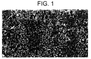
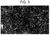
- the particulate phase is removed to leave behind the structure shown in the micrograph of FIG. 3, and illustrated in FIG. 4.
- the component now has a "moon-crater" like structure, defined by overlay coating 23 having ridges 20 that form an interconnected network, and discrete depressions 21.
- the overlay coating is formed of a single, homogeneous phase, as in the case of solidified braze alloy.
- the particulates were formed of NiCrAlY, in a nickel-base braze alloy matrix (19 wt% Cr, 10 wt% Si, balance Ni). The particulates were had a -50 to +80 mesh size, and were adhered to a green braze tape containing the above braze alloy.
- the tape was adhered to a substrate, and fused in place at a temperature of 2100 °F.
- the particulates were removed by exposure of the particulates to a 1:1:1 bath of water, hydrochloric acid (HCl), and HNO 3 (nitric acid) for a duration of 3 hours at 70°C.
- HCl hydrochloric acid
- HNO 3 nitric acid
- other particulate/etchant systems can be utilized, provided that the particulates do not adversely react with the material of the matrix phase during fusing and that the particulates are removed selectively from the matrix.
- it is generally desirable to remove the layer such that the particles are directly exposed to the etchant. Such removal can be carried out by various means, including light grit blasting and brief exposure to an etchant to remove the film.
- the depressions 21 have a concave contour, due to removal of generally spherical particles. It is expected that this contour shall be particularly effective at increasing the heat transfer of the treated component.
- the concave contour increases surface area with minimal added mass, which is important to reduce the heat conduction path length, the path length of phonons that propagate through the overlay coating 23.
- the term "concave" as used in connection with the depressions according to embodiments of the present invention means that in a cross-section extending through the bottom point of the depression, the depression is bounded by two line segments, each of which is concave as viewed from an exterior of the depression. Concavity of a depression according to an embodiment of the present invention is described in more detail below.
- each depression has a bottom point 24, which is the bottom-most point of the depression.
- the depressions 21 are generally hemispherical, and the bottom point 24 is located at the geometric center of the depression.
- the cross-section of FIG. 5 is taken through the bottom point 24, and bisects the depression 21.
- a first line segment 25 is defined, extending from a first side of ridge 20 to bottom point 24, and a second line segment 26, extending from a second side of ridge 20 to bottom point 24.
- each of the first and second line segments 25 and 26 is concave as viewed from an exterior of the depression 21, along a direction normal to the line segment.
- the entirety of each line segment along its length is concave; each line segment has no convex portions.
- depression 21 has a diameter d .
- the diameter d generally corresponds to the size of the particulates of the depression-producing phase. Accordingly, the average diameter d is on the order of about 125 to about 4000 microns, such as about 125 to 2050 microns.
- the depression 21 has a radius of curvature on the order of about 75 to about 2000 microns, such as about 75 to 1000 microns.
- the radius of curvature shown in the drawings is generally constant through the entirety of the depression due to the hemispherical contour of the depression. However, the radius of curvature need not be constant, such as is the case when non-spherical particles are used to form the depressions.
- non-hemispherical depressions have a radius of curvature at several points along the depression that fall within the values stated above.
- the ridge 20 shown in FIG. 5 forms a defined peak due to wetting action of the braze alloy along the outer surface of a particle of the depression-producing phase.
- the ridges need not be sharp, as shown in FIG. 6. Rounding of the ridge can be due to various factors, including a low degree of wetting of the matrix phase to the depression-producing phase during fusing, or erosion of the ridge by action of the etchant during the etch treatment.
- Also shown in FIG. 6 is a case where two particles of the depression-producing phase did not touch or closely pack together.
- ridge 20, defining the rim of one depression is separated from ridge 30 by a plateau 28. Such plateaus are generally present throughout the treated or textured surface, and form an interconnected network of ridges.
- a textured surface having visible depressions, is formed in an overlay layer.
- the material of the layer may be chosen to enhance certain properties of the component.
- the overlay layer may have desirable thermal conductivity, corrosion resistance, and oxidation resistance.
- a turbine engine component having enhanced heat transfer is made directly during the casting operation, rather than by using the subtractive method described above, where a depression-producing phase is selectively removed from a matrix phase.
- molten alloy is injected into a mold which has an inner surface that is textured with bumps or protuberances. Accordingly, the base material of the component forms the texturing rather than an overlay coating.
- Suitable molten alloys include those mentioned above, such as cobalt- or nickel-based superalloys.
- the protuberances typically have the same characteristics as the particulate phase described above with respect to the prior embodiment.
- the protuberances are generally spherical, having an average aspect ratio less than 2.0, typically less than about 1.5, and more particularly, not greater than about 1.2.
- the protuberances have an average height on the order 125 to about 4000 microns, such as about 125 to about 2050 microns.
- the mold may be manufactured by one of various techniques used in the art, such as what is known as the "lost wax process.”
- the mold is formed of a ceramic material to withstand the high temperatures generally associated with casting a molten alloy. Typical ceramic materials include alumina, silica, and combinations thereof.
- Molds for casting typically have an outer shell and an inner core.
- the textured surface is along an interior of a part, such as an inner surface defining an internal cavity
- an outer surface of the inner core is textured with the protuberances or bumps as described above.
- a typical example of such a component is a turbine blade which receives backside coolant flow.
- the alloy is allowed to cool and solidify.
- the mold is then separated from the component.
- a portion of the mold, such as the inner core, is destroyed in order to separate the mold from the cast component.
- the cast component has a textured surface that mimics or is complementary to the protuberance-containing surface of the mold. That is, the cast component has a plurality of recesses that are complementary to the protuberances of the mold.
- the geometrical characteristics of the textured surface, including contour, size, and shape of the recesses and ridges are as stated above for the embodiment formed using subtractive techniques.
- the average depth of the depressions as measured from the ridge to the bottom point is on order of about 75 microns to about 2000 microns, particularly about 75 microns to about 1000 microns.
- the density of depressions generally is at least 25 depressions/cm 2 , typically not less than 100 depressions/cm 2 , and desirably not less than 500 depressions/cm 2 . In one embodiment, the depression density was about 1100 depressions/cm 2 , and another 3100 depressions/cm 2 .
- area enhancement A/A 0 where A is the surface area of the treated region of the component and A 0 is the surface area of the same region of the component in untreated form (generally a smooth surface), is generally at least about 1.05, typically at least about 1.20.
- Area enhancement A/A 0 is desirably at least about 1.50.
- A/A 0 is generally less than about 4.0, typically less than about 2.5.
- the textured surface containing ridges and depressions or recesses is present to enhance the heat transfer characteristics for the underlying component.
- the enhanced heat transfer characteristics in turn result in a desirable temperature reduction for specified regions of the component, leading to a desirable reduction in thermal stress.
- the heat transfer enhancement can also be adjusted, which in turn results in a reduction in the thermal and stress gradients for the component.
- the depth of the depressions is not greater than 600 microns, more particularly, less than about 375 microns to improve fin efficiency.
- Texturing can be applied to a wide variety of turbine engine components.
- other superalloy components including combustor liners, combustor domes, buckets or blades, nozzles, vanes, airfoils, or shrouds.
- Non-superalloy components used in lower temperature applications may also be treated.
- shroud clearance control areas including flanges, casings, and rings may be advantageously treated.
- use of texturing permits more accurate control of the diameter of the flowpath shroud, thereby decreasing the clearance between the blade tip and shroud surface and increasing efficiency.
- the braze alloy may be replaced with another bonding agent such as a high temperature epoxy or solder, for example.
- cooling is generally carried out by impingement cooling, that is, with a coolant medium that is directed perpendicularly against a component used in a high temperature environment.
- impingement cooling represents a preferable form of cooling
- the coolant medium can be directed at varying angles with respect to the textured surface.
- the coolant medium is usually air, it could also be composed of other fluids such as water.
- a textured surface is cast-in or provided in the form of an overlay coating to improve heat transfer.
- the increase in heat transfer is believed to be largely due to the increased surface area of the treated component.
- the textured surface may also increase heat transfer by modifying the coolant medium flow characteristics, such as from laminar flow to turbulated flow along the surface.
- embodiments of the present invention methods are provided that permit texturing of surfaces that are not easily accessible, to provide improved heat transfer. Further, embodiments of the present invention enable formation of a depression/ridge system of varying sizes and geometries, and in patterns, if desired. Because the textured surface on the turbine engine component has increased surface area and minimal material mass, heat transfer is further improved by reducing phonon path length through the component.
Landscapes
- Engineering & Computer Science (AREA)
- Mechanical Engineering (AREA)
- General Engineering & Computer Science (AREA)
- Physics & Mathematics (AREA)
- Thermal Sciences (AREA)
- Chemical & Material Sciences (AREA)
- Crystallography & Structural Chemistry (AREA)
- Other Surface Treatments For Metallic Materials (AREA)
- Turbine Rotor Nozzle Sealing (AREA)
- Molds, Cores, And Manufacturing Methods Thereof (AREA)
Applications Claiming Priority (2)
| Application Number | Priority Date | Filing Date | Title |
|---|---|---|---|
| US09/345,541 US6589600B1 (en) | 1999-06-30 | 1999-06-30 | Turbine engine component having enhanced heat transfer characteristics and method for forming same |
| US345541 | 2003-01-16 |
Publications (3)
| Publication Number | Publication Date |
|---|---|
| EP1065345A2 true EP1065345A2 (de) | 2001-01-03 |
| EP1065345A3 EP1065345A3 (de) | 2004-04-07 |
| EP1065345B1 EP1065345B1 (de) | 2013-09-25 |
Family
ID=23355445
Family Applications (1)
| Application Number | Title | Priority Date | Filing Date |
|---|---|---|---|
| EP00305461.6A Expired - Lifetime EP1065345B1 (de) | 1999-06-30 | 2000-06-29 | Turbinenelement mit erhöhter Wärmeleitfähigkeit und dessen Herstellungsweise |
Country Status (4)
| Country | Link |
|---|---|
| US (1) | US6589600B1 (de) |
| EP (1) | EP1065345B1 (de) |
| JP (1) | JP2001164901A (de) |
| KR (1) | KR20010049669A (de) |
Cited By (12)
| Publication number | Priority date | Publication date | Assignee | Title |
|---|---|---|---|---|
| DE10159668A1 (de) * | 2001-12-05 | 2003-06-18 | Rolls Royce Deutschland | Brennkammerkopf |
| EP1116537A3 (de) * | 2000-01-10 | 2003-06-25 | General Electric Company | Gussstück mit verbesserter Wärmeübertragungsfläche, sowie Giessform und Modell zu ihrer Herstellung |
| US6786982B2 (en) | 2000-01-10 | 2004-09-07 | General Electric Company | Casting having an enhanced heat transfer, surface, and mold and pattern for forming same |
| EP1598523A1 (de) * | 2004-05-18 | 2005-11-23 | Snecma | Wandstruktur für hohle Gasturbinenschaufeln zur Verbesserung des Wärmeübergangs |
| EP1541877A4 (de) * | 2002-06-27 | 2006-01-25 | Asahi Tec Corp | Objekt, dessen oberfläche zu behandeln ist, oberflächenbehandlungsverfahren und flächenbehandlungsvorrichtung |
| US7094476B2 (en) | 2002-06-27 | 2006-08-22 | Asahi Tec Corporation | Surface-treated product, surface-treatment method, and surface-treatment apparatus |
| EP1413829A3 (de) * | 2002-10-24 | 2006-10-18 | General Electric Company | Brennkammerwand mit umgekehrten Wirbelelementen |
| EP1775420A3 (de) * | 2005-10-11 | 2008-08-20 | Honeywell International Inc. | Verfahren zur Herstellung einer Schaufel mit Innenkühlungskanälen |
| WO2012143057A1 (de) * | 2011-04-21 | 2012-10-26 | Klimtex Gmbh | Gussteil mit aussparungen |
| RU2522156C2 (ru) * | 2012-07-17 | 2014-07-10 | Федеральное государственное бюджетное образовательное учреждение высшего профессионального образования "Юго-Западный государственный университет" (ЮЗ ГУ) | Теплотрубный контур охлаждения лопатки турбины |
| EP2853324A3 (de) * | 2013-09-27 | 2015-09-30 | Pratt & Whitney Canada Corp. | Verfahren zur Erzeugung einer Oberflächenstruktur |
| EP3179037A1 (de) * | 2015-12-10 | 2017-06-14 | General Electric Company | Rippen für eine schaufel eines gasturbinenmotors |
Families Citing this family (36)
| Publication number | Priority date | Publication date | Assignee | Title |
|---|---|---|---|---|
| US6624225B1 (en) * | 1996-06-03 | 2003-09-23 | Liburdi Engineering Limited | Wide-gap filler material |
| KR100487520B1 (ko) * | 2002-02-08 | 2005-05-03 | 삼성전자주식회사 | 스크린 프린트법을 위한 범프용 페이스트 제조 방법 |
| US6722134B2 (en) * | 2002-09-18 | 2004-04-20 | General Electric Company | Linear surface concavity enhancement |
| US6761031B2 (en) * | 2002-09-18 | 2004-07-13 | General Electric Company | Double wall combustor liner segment with enhanced cooling |
| US6910620B2 (en) * | 2002-10-15 | 2005-06-28 | General Electric Company | Method for providing turbulation on the inner surface of holes in an article, and related articles |
| US6681578B1 (en) | 2002-11-22 | 2004-01-27 | General Electric Company | Combustor liner with ring turbulators and related method |
| DE10343049B3 (de) * | 2003-09-16 | 2005-04-14 | Eads Space Transportation Gmbh | Brennkammer mit Kühleinrichtung und Verfahren zur Herstellung der Brennkammer |
| US7186084B2 (en) * | 2003-11-19 | 2007-03-06 | General Electric Company | Hot gas path component with mesh and dimpled cooling |
| US6984102B2 (en) | 2003-11-19 | 2006-01-10 | General Electric Company | Hot gas path component with mesh and turbulated cooling |
| US7302990B2 (en) * | 2004-05-06 | 2007-12-04 | General Electric Company | Method of forming concavities in the surface of a metal component, and related processes and articles |
| US7007482B2 (en) * | 2004-05-28 | 2006-03-07 | Power Systems Mfg., Llc | Combustion liner seal with heat transfer augmentation |
| US20080104961A1 (en) * | 2006-11-08 | 2008-05-08 | Ronald Scott Bunker | Method and apparatus for enhanced mixing in premixing devices |
| US7919151B2 (en) * | 2006-12-14 | 2011-04-05 | General Electric Company | Methods of preparing wetting-resistant surfaces and articles incorporating the same |
| US7871244B2 (en) * | 2007-02-15 | 2011-01-18 | Siemens Energy, Inc. | Ring seal for a turbine engine |
| US7819625B2 (en) * | 2007-05-07 | 2010-10-26 | Siemens Energy, Inc. | Abradable CMC stacked laminate ring segment for a gas turbine |
| US20080295996A1 (en) * | 2007-05-31 | 2008-12-04 | Auburn University | Stable cavity-induced two-phase heat transfer in silicon microchannels |
| US8079806B2 (en) * | 2007-11-28 | 2011-12-20 | United Technologies Corporation | Segmented ceramic layer for member of gas turbine engine |
| TWM381055U (en) * | 2009-11-25 | 2010-05-21 | Asia Vital Components Co Ltd | Fin structure for heat exchanger and heat exchanger thereof |
| US9376960B2 (en) * | 2010-07-23 | 2016-06-28 | University Of Central Florida Research Foundation, Inc. | Heat transfer augmented fluid flow surfaces |
| KR101879360B1 (ko) * | 2010-08-26 | 2018-07-18 | 보르그워너 인코퍼레이티드 | 배기가스 터보차저 부품 |
| US20130022444A1 (en) * | 2011-07-19 | 2013-01-24 | Sudhakar Neeli | Low pressure turbine exhaust diffuser with turbulators |
| US8828312B2 (en) | 2011-12-08 | 2014-09-09 | Kennametal Inc. | Dilution control in hardfacing severe service components |
| JP5885625B2 (ja) * | 2012-09-12 | 2016-03-15 | 株式会社東芝 | トランジションピースの損傷補修方法およびトランジションピース |
| US8951004B2 (en) * | 2012-10-23 | 2015-02-10 | Siemens Aktiengesellschaft | Cooling arrangement for a gas turbine component |
| US10329917B2 (en) * | 2013-03-05 | 2019-06-25 | United Technologies Corporation | Gas turbine engine component external surface micro-channel cooling |
| EP2971547B1 (de) * | 2013-03-12 | 2020-01-01 | United Technologies Corporation | Freitragender stator mit wirbelerzeugungsfunktion |
| US20160025010A1 (en) * | 2013-03-26 | 2016-01-28 | United Technologies Corporation | Turbine engine and turbine engine component with cooling pedestals |
| US10434607B2 (en) | 2013-08-01 | 2019-10-08 | United Technologies Corporation | Method to immobilize an entrapped contaminant within a honeycomb structure |
| US10041890B2 (en) | 2015-08-04 | 2018-08-07 | United Technologies Corporation | Radiopaque protective fill for manufacture, repair, or remanufacture of cooled components |
| US10052724B2 (en) * | 2016-03-02 | 2018-08-21 | General Electric Company | Braze composition, brazing process, and brazed article |
| US10605087B2 (en) * | 2017-12-14 | 2020-03-31 | United Technologies Corporation | CMC component with flowpath surface ribs |
| JP7105360B2 (ja) * | 2018-07-13 | 2022-07-22 | シーメンス エナジー グローバル ゲゼルシャフト ミット ベシュレンクテル ハフツング ウント コンパニー コマンディートゲゼルシャフト | ピンを備えるタービンエンジン用の翼型 |
| US11517969B2 (en) * | 2019-01-24 | 2022-12-06 | General Electric Company | Weld-brazing techniques |
| US11397059B2 (en) | 2019-09-17 | 2022-07-26 | General Electric Company | Asymmetric flow path topology |
| US11753723B2 (en) * | 2020-06-02 | 2023-09-12 | The Boeing Company | Systems and methods for cold spray additive manufacture with superplastic formation diffusion bonding |
| US11962188B2 (en) | 2021-01-21 | 2024-04-16 | General Electric Company | Electric machine |
Family Cites Families (34)
| Publication number | Priority date | Publication date | Assignee | Title |
|---|---|---|---|---|
| BE432599A (de) * | 1938-02-08 | |||
| US2648519A (en) * | 1948-04-22 | 1953-08-11 | Campini Secondo | Cooling combustion turbines |
| US3700418A (en) * | 1969-11-24 | 1972-10-24 | Gen Motors Corp | Cooled airfoil and method of making it |
| US3975165A (en) * | 1973-12-26 | 1976-08-17 | Union Carbide Corporation | Graded metal-to-ceramic structure for high temperature abradable seal applications and a method of producing said |
| US4003716A (en) | 1974-07-15 | 1977-01-18 | Gte Sylvania Incorporated | Cast cemented refractory metal carbides having improved sintered density |
| US4116723A (en) | 1976-11-17 | 1978-09-26 | United Technologies Corporation | Heat treated superalloy single crystal article and process |
| JPS54108053A (en) * | 1978-02-14 | 1979-08-24 | Babcock Hitachi Kk | Heat transmission element |
| JPS5528483A (en) * | 1978-08-22 | 1980-02-29 | Mitsubishi Electric Corp | Heat transfer surface and its preparation |
| US5399313A (en) | 1981-10-02 | 1995-03-21 | General Electric Company | Nickel-based superalloys for producing single crystal articles having improved tolerance to low angle grain boundaries |
| JPS59113204A (ja) * | 1982-12-20 | 1984-06-29 | Hitachi Ltd | 冷却翼 |
| US4689242A (en) | 1986-07-21 | 1987-08-25 | United Technologies Corporation | Method for adhesion of grit to blade tips |
| DE3635369A1 (de) | 1986-10-17 | 1988-04-28 | Degussa | Verfahren zum beschichten von oberflaechen mit hartstoffen |
| FR2607198B1 (fr) * | 1986-11-26 | 1990-05-04 | Snecma | Carter de compresseur adapte pour le pilotage actif de ses dilatations et son procede de fabrication |
| US4938991A (en) | 1987-03-25 | 1990-07-03 | Dresser Industries, Inc. | Surface protection method and article formed thereby |
| US4884820A (en) * | 1987-05-19 | 1989-12-05 | Union Carbide Corporation | Wear resistant, abrasive laser-engraved ceramic or metallic carbide surfaces for rotary labyrinth seal members |
| DE58907451D1 (de) * | 1988-10-12 | 1994-05-19 | Ruhrgas Ag | Brenner, insbesondere Hochgeschwindigkeitsbrenner. |
| US5096375A (en) * | 1989-09-08 | 1992-03-17 | General Electric Company | Radial adjustment mechanism for blade tip clearance control apparatus |
| JP2580843B2 (ja) * | 1990-06-07 | 1997-02-12 | 三菱電機株式会社 | 表面部が多孔状である基材の製造方法 |
| US5210944A (en) * | 1990-11-13 | 1993-05-18 | General Electric Company | Method for making a gas turbine engine component |
| US5304032A (en) * | 1991-07-22 | 1994-04-19 | Bosna Alexander A | Abradable non-metallic seal for rotating turbine engines |
| US5353865A (en) | 1992-03-30 | 1994-10-11 | General Electric Company | Enhanced impingement cooled components |
| JP3091071B2 (ja) * | 1993-02-24 | 2000-09-25 | 株式会社日立製作所 | 熱交換器及び吸収冷暖房機 |
| KR0132015B1 (ko) | 1993-02-24 | 1998-04-20 | 가나이 쯔도무 | 열 교환기 |
| JP3315785B2 (ja) | 1993-12-14 | 2002-08-19 | 株式会社神戸製鋼所 | 吸収器用伝熱管 |
| US5549927A (en) | 1994-03-01 | 1996-08-27 | Modine Manufacturing Company | Modified substrate surface and method |
| EP0780484B1 (de) * | 1995-12-22 | 2001-09-26 | General Electric Company | Körper mit Hochtemperatur-Schutzschicht und Verfahren zum Beschichten |
| JPH107477A (ja) * | 1996-06-19 | 1998-01-13 | Toshiba Corp | セラミックス部材の保護被膜構造、ガスタービン翼、ボールベアリングおよび被膜検査方法 |
| US5858558A (en) * | 1996-10-30 | 1999-01-12 | General Electric Company | Nickel-base sigma-gamma in-situ intermetallic matrix composite |
| US5951892A (en) * | 1996-12-10 | 1999-09-14 | Chromalloy Gas Turbine Corporation | Method of making an abradable seal by laser cutting |
| EP0905353B1 (de) * | 1997-09-30 | 2003-01-15 | ALSTOM (Switzerland) Ltd | Prallanordnung für ein konvektives Kühl- oder Heizverfahren |
| US6098397A (en) * | 1998-06-08 | 2000-08-08 | Caterpillar Inc. | Combustor for a low-emissions gas turbine engine |
| US6113347A (en) * | 1998-12-28 | 2000-09-05 | General Electric Company | Blade containment system |
| US6155778A (en) * | 1998-12-30 | 2000-12-05 | General Electric Company | Recessed turbine shroud |
| US6142734A (en) * | 1999-04-06 | 2000-11-07 | General Electric Company | Internally grooved turbine wall |
-
1999
- 1999-06-30 US US09/345,541 patent/US6589600B1/en not_active Expired - Fee Related
-
2000
- 2000-06-29 EP EP00305461.6A patent/EP1065345B1/de not_active Expired - Lifetime
- 2000-06-29 JP JP2000195380A patent/JP2001164901A/ja not_active Ceased
- 2000-06-29 KR KR1020000036529A patent/KR20010049669A/ko not_active Ceased
Non-Patent Citations (1)
| Title |
|---|
| None |
Cited By (18)
| Publication number | Priority date | Publication date | Assignee | Title |
|---|---|---|---|---|
| EP1116537A3 (de) * | 2000-01-10 | 2003-06-25 | General Electric Company | Gussstück mit verbesserter Wärmeübertragungsfläche, sowie Giessform und Modell zu ihrer Herstellung |
| US6786982B2 (en) | 2000-01-10 | 2004-09-07 | General Electric Company | Casting having an enhanced heat transfer, surface, and mold and pattern for forming same |
| EP1498198A1 (de) * | 2000-01-10 | 2005-01-19 | General Electric Company | Verfahren zur Herstellung eines Gussstücks mit verbesserter Wärmeübertragungsfläche und Wachsmodell zu ihrer Herstellung |
| DE10159668A1 (de) * | 2001-12-05 | 2003-06-18 | Rolls Royce Deutschland | Brennkammerkopf |
| CN1321271C (zh) * | 2002-06-27 | 2007-06-13 | 旭技术株式会社 | 表面加工件和表面加工方法及表面加工装置 |
| US7458881B2 (en) | 2002-06-27 | 2008-12-02 | Asahi Tec Corporation | Surface treated product, surface treatment method, and surface treatment apparatus |
| EP1541877A4 (de) * | 2002-06-27 | 2006-01-25 | Asahi Tec Corp | Objekt, dessen oberfläche zu behandeln ist, oberflächenbehandlungsverfahren und flächenbehandlungsvorrichtung |
| US7094476B2 (en) | 2002-06-27 | 2006-08-22 | Asahi Tec Corporation | Surface-treated product, surface-treatment method, and surface-treatment apparatus |
| EP1413829A3 (de) * | 2002-10-24 | 2006-10-18 | General Electric Company | Brennkammerwand mit umgekehrten Wirbelelementen |
| EP1598523A1 (de) * | 2004-05-18 | 2005-11-23 | Snecma | Wandstruktur für hohle Gasturbinenschaufeln zur Verbesserung des Wärmeübergangs |
| FR2870560A1 (fr) * | 2004-05-18 | 2005-11-25 | Snecma Moteurs Sa | Circuit de refroidissement a cavite a rapport de forme eleve pour aube de turbine a gaz |
| US7513737B2 (en) | 2004-05-18 | 2009-04-07 | Snecma | Gas turbine blade cooling circuit having a cavity with a high aspect ratio |
| EP1775420A3 (de) * | 2005-10-11 | 2008-08-20 | Honeywell International Inc. | Verfahren zur Herstellung einer Schaufel mit Innenkühlungskanälen |
| WO2012143057A1 (de) * | 2011-04-21 | 2012-10-26 | Klimtex Gmbh | Gussteil mit aussparungen |
| RU2522156C2 (ru) * | 2012-07-17 | 2014-07-10 | Федеральное государственное бюджетное образовательное учреждение высшего профессионального образования "Юго-Западный государственный университет" (ЮЗ ГУ) | Теплотрубный контур охлаждения лопатки турбины |
| EP2853324A3 (de) * | 2013-09-27 | 2015-09-30 | Pratt & Whitney Canada Corp. | Verfahren zur Erzeugung einer Oberflächenstruktur |
| EP3179037A1 (de) * | 2015-12-10 | 2017-06-14 | General Electric Company | Rippen für eine schaufel eines gasturbinenmotors |
| US10107302B2 (en) | 2015-12-10 | 2018-10-23 | General Electric Company | Durable riblets for engine environment |
Also Published As
| Publication number | Publication date |
|---|---|
| EP1065345B1 (de) | 2013-09-25 |
| US6589600B1 (en) | 2003-07-08 |
| KR20010049669A (ko) | 2001-06-15 |
| JP2001164901A (ja) | 2001-06-19 |
| EP1065345A3 (de) | 2004-04-07 |
Similar Documents
| Publication | Publication Date | Title |
|---|---|---|
| US6589600B1 (en) | Turbine engine component having enhanced heat transfer characteristics and method for forming same | |
| EP1050663B1 (de) | Gegenstand mit Höckern zur Herstellung einer turbulenten Strömung sowie Verfahren zur Herstellung von Höckern auf einem Gegenstand | |
| US6402464B1 (en) | Enhanced heat transfer surface for cast-in-bump-covered cooling surfaces and methods of enhancing heat transfer | |
| US6546730B2 (en) | Method and apparatus for enhancing heat transfer in a combustor liner for a gas turbine | |
| EP1378583B1 (de) | Herstellungsverfahren für einen Hohlkanal auf der Oberfläche eines metallischen Substrats, und verwandte Artikel | |
| US6451454B1 (en) | Turbine engine component having wear coating and method for coating a turbine engine component | |
| US6355356B1 (en) | Coating system for providing environmental protection to a metal substrate, and related processes | |
| US6210812B1 (en) | Thermal barrier coating system | |
| EP1516942A1 (de) | Verfahren zum Beschichten eines Substrats | |
| EP1559868A2 (de) | Verfahren zur Wiederherstellung der Abmessungen eines Schaufelprofils und Vorformung dafür | |
| US6910620B2 (en) | Method for providing turbulation on the inner surface of holes in an article, and related articles | |
| US6505673B1 (en) | Method for forming a turbine engine component having enhanced heat transfer characteristics | |
| US20170368647A1 (en) | Methods for repairing film holes in a surface | |
| US6921582B2 (en) | Oxidation-resistant coatings bonded to metal substrates, and related articles and processes | |
| US6426152B1 (en) | Salvaged castings and methods of salvaging castings with defective cast cooling bumps | |
| CZ20002453A3 (cs) | Součást turbínového motoru s vylepšenými charakteristikami přenosu tepla a způsob její výroby |
Legal Events
| Date | Code | Title | Description |
|---|---|---|---|
| PUAI | Public reference made under article 153(3) epc to a published international application that has entered the european phase |
Free format text: ORIGINAL CODE: 0009012 |
|
| AK | Designated contracting states |
Kind code of ref document: A2 Designated state(s): AT BE CH CY DE DK ES FI FR GB GR IE IT LI LU MC NL PT SE |
|
| AX | Request for extension of the european patent |
Free format text: AL;LT;LV;MK;RO;SI |
|
| PUAL | Search report despatched |
Free format text: ORIGINAL CODE: 0009013 |
|
| AK | Designated contracting states |
Kind code of ref document: A3 Designated state(s): AT BE CH CY DE DK ES FI FR GB GR IE IT LI LU MC NL PT SE |
|
| AX | Request for extension of the european patent |
Extension state: AL LT LV MK RO SI |
|
| AKX | Designation fees paid | ||
| 17P | Request for examination filed |
Effective date: 20041007 |
|
| RBV | Designated contracting states (corrected) |
Designated state(s): AT BE CH CY DE DK ES FI FR GB GR IE IT LI LU MC NL PT SE |
|
| REG | Reference to a national code |
Ref country code: DE Ref legal event code: 8566 |
|
| GRAP | Despatch of communication of intention to grant a patent |
Free format text: ORIGINAL CODE: EPIDOSNIGR1 |
|
| INTG | Intention to grant announced |
Effective date: 20130419 |
|
| GRAS | Grant fee paid |
Free format text: ORIGINAL CODE: EPIDOSNIGR3 |
|
| GRAA | (expected) grant |
Free format text: ORIGINAL CODE: 0009210 |
|
| AK | Designated contracting states |
Kind code of ref document: B1 Designated state(s): AT BE CH CY DE DK ES FI FR GB GR IE IT LI LU MC NL PT SE |
|
| REG | Reference to a national code |
Ref country code: GB Ref legal event code: FG4D |
|
| REG | Reference to a national code |
Ref country code: CH Ref legal event code: EP |
|
| REG | Reference to a national code |
Ref country code: AT Ref legal event code: REF Ref document number: 633795 Country of ref document: AT Kind code of ref document: T Effective date: 20131015 |
|
| REG | Reference to a national code |
Ref country code: IE Ref legal event code: FG4D |
|
| REG | Reference to a national code |
Ref country code: DE Ref legal event code: R096 Ref document number: 60048268 Country of ref document: DE Effective date: 20131121 |
|
| PG25 | Lapsed in a contracting state [announced via postgrant information from national office to epo] |
Ref country code: SE Free format text: LAPSE BECAUSE OF FAILURE TO SUBMIT A TRANSLATION OF THE DESCRIPTION OR TO PAY THE FEE WITHIN THE PRESCRIBED TIME-LIMIT Effective date: 20130925 |
|
| REG | Reference to a national code |
Ref country code: AT Ref legal event code: MK05 Ref document number: 633795 Country of ref document: AT Kind code of ref document: T Effective date: 20130925 |
|
| REG | Reference to a national code |
Ref country code: NL Ref legal event code: VDEP Effective date: 20130925 |
|
| PG25 | Lapsed in a contracting state [announced via postgrant information from national office to epo] |
Ref country code: FI Free format text: LAPSE BECAUSE OF FAILURE TO SUBMIT A TRANSLATION OF THE DESCRIPTION OR TO PAY THE FEE WITHIN THE PRESCRIBED TIME-LIMIT Effective date: 20130925 Ref country code: GR Free format text: LAPSE BECAUSE OF FAILURE TO SUBMIT A TRANSLATION OF THE DESCRIPTION OR TO PAY THE FEE WITHIN THE PRESCRIBED TIME-LIMIT Effective date: 20131226 |
|
| PG25 | Lapsed in a contracting state [announced via postgrant information from national office to epo] |
Ref country code: BE Free format text: LAPSE BECAUSE OF FAILURE TO SUBMIT A TRANSLATION OF THE DESCRIPTION OR TO PAY THE FEE WITHIN THE PRESCRIBED TIME-LIMIT Effective date: 20130925 |
|
| PG25 | Lapsed in a contracting state [announced via postgrant information from national office to epo] |
Ref country code: NL Free format text: LAPSE BECAUSE OF FAILURE TO SUBMIT A TRANSLATION OF THE DESCRIPTION OR TO PAY THE FEE WITHIN THE PRESCRIBED TIME-LIMIT Effective date: 20130925 |
|
| PG25 | Lapsed in a contracting state [announced via postgrant information from national office to epo] |
Ref country code: AT Free format text: LAPSE BECAUSE OF FAILURE TO SUBMIT A TRANSLATION OF THE DESCRIPTION OR TO PAY THE FEE WITHIN THE PRESCRIBED TIME-LIMIT Effective date: 20130925 Ref country code: CY Free format text: LAPSE BECAUSE OF FAILURE TO SUBMIT A TRANSLATION OF THE DESCRIPTION OR TO PAY THE FEE WITHIN THE PRESCRIBED TIME-LIMIT Effective date: 20130925 Ref country code: ES Free format text: LAPSE BECAUSE OF FAILURE TO SUBMIT A TRANSLATION OF THE DESCRIPTION OR TO PAY THE FEE WITHIN THE PRESCRIBED TIME-LIMIT Effective date: 20130925 |
|
| REG | Reference to a national code |
Ref country code: DE Ref legal event code: R097 Ref document number: 60048268 Country of ref document: DE |
|
| PG25 | Lapsed in a contracting state [announced via postgrant information from national office to epo] |
Ref country code: PT Free format text: LAPSE BECAUSE OF FAILURE TO SUBMIT A TRANSLATION OF THE DESCRIPTION OR TO PAY THE FEE WITHIN THE PRESCRIBED TIME-LIMIT Effective date: 20140127 |
|
| PLBE | No opposition filed within time limit |
Free format text: ORIGINAL CODE: 0009261 |
|
| STAA | Information on the status of an ep patent application or granted ep patent |
Free format text: STATUS: NO OPPOSITION FILED WITHIN TIME LIMIT |
|
| PG25 | Lapsed in a contracting state [announced via postgrant information from national office to epo] |
Ref country code: IT Free format text: LAPSE BECAUSE OF FAILURE TO SUBMIT A TRANSLATION OF THE DESCRIPTION OR TO PAY THE FEE WITHIN THE PRESCRIBED TIME-LIMIT Effective date: 20130925 |
|
| 26N | No opposition filed |
Effective date: 20140626 |
|
| PG25 | Lapsed in a contracting state [announced via postgrant information from national office to epo] |
Ref country code: DK Free format text: LAPSE BECAUSE OF FAILURE TO SUBMIT A TRANSLATION OF THE DESCRIPTION OR TO PAY THE FEE WITHIN THE PRESCRIBED TIME-LIMIT Effective date: 20130925 |
|
| REG | Reference to a national code |
Ref country code: DE Ref legal event code: R097 Ref document number: 60048268 Country of ref document: DE Effective date: 20140626 |
|
| REG | Reference to a national code |
Ref country code: DE Ref legal event code: R119 Ref document number: 60048268 Country of ref document: DE |
|
| PG25 | Lapsed in a contracting state [announced via postgrant information from national office to epo] |
Ref country code: MC Free format text: LAPSE BECAUSE OF FAILURE TO SUBMIT A TRANSLATION OF THE DESCRIPTION OR TO PAY THE FEE WITHIN THE PRESCRIBED TIME-LIMIT Effective date: 20130925 Ref country code: LU Free format text: LAPSE BECAUSE OF FAILURE TO SUBMIT A TRANSLATION OF THE DESCRIPTION OR TO PAY THE FEE WITHIN THE PRESCRIBED TIME-LIMIT Effective date: 20140629 |
|
| REG | Reference to a national code |
Ref country code: CH Ref legal event code: PL |
|
| GBPC | Gb: european patent ceased through non-payment of renewal fee |
Effective date: 20140629 |
|
| REG | Reference to a national code |
Ref country code: IE Ref legal event code: MM4A |
|
| REG | Reference to a national code |
Ref country code: FR Ref legal event code: ST Effective date: 20150227 |
|
| REG | Reference to a national code |
Ref country code: DE Ref legal event code: R119 Ref document number: 60048268 Country of ref document: DE Effective date: 20150101 |
|
| PG25 | Lapsed in a contracting state [announced via postgrant information from national office to epo] |
Ref country code: IE Free format text: LAPSE BECAUSE OF NON-PAYMENT OF DUE FEES Effective date: 20140629 Ref country code: CH Free format text: LAPSE BECAUSE OF NON-PAYMENT OF DUE FEES Effective date: 20140630 Ref country code: DE Free format text: LAPSE BECAUSE OF NON-PAYMENT OF DUE FEES Effective date: 20150101 Ref country code: LI Free format text: LAPSE BECAUSE OF NON-PAYMENT OF DUE FEES Effective date: 20140630 |
|
| PG25 | Lapsed in a contracting state [announced via postgrant information from national office to epo] |
Ref country code: FR Free format text: LAPSE BECAUSE OF NON-PAYMENT OF DUE FEES Effective date: 20140630 Ref country code: GB Free format text: LAPSE BECAUSE OF NON-PAYMENT OF DUE FEES Effective date: 20140629 |