EP1065379B1 - Elektrohydraulische Druckversorgung mit verstellbarer Pumpe und regelbarem elektrischem Antrieb - Google Patents
Elektrohydraulische Druckversorgung mit verstellbarer Pumpe und regelbarem elektrischem Antrieb Download PDFInfo
- Publication number
- EP1065379B1 EP1065379B1 EP00110414A EP00110414A EP1065379B1 EP 1065379 B1 EP1065379 B1 EP 1065379B1 EP 00110414 A EP00110414 A EP 00110414A EP 00110414 A EP00110414 A EP 00110414A EP 1065379 B1 EP1065379 B1 EP 1065379B1
- Authority
- EP
- European Patent Office
- Prior art keywords
- pump
- control
- pressure
- displacement
- unit according
- Prior art date
- Legal status (The legal status is an assumption and is not a legal conclusion. Google has not performed a legal analysis and makes no representation as to the accuracy of the status listed.)
- Expired - Lifetime
Links
- 238000006073 displacement reaction Methods 0.000 title claims abstract description 58
- 101150104728 GPR88 gene Proteins 0.000 claims abstract 3
- 230000002441 reversible effect Effects 0.000 claims description 25
- 238000010586 diagram Methods 0.000 description 15
- 230000008901 benefit Effects 0.000 description 9
- 230000008859 change Effects 0.000 description 4
- 238000005457 optimization Methods 0.000 description 4
- 230000001105 regulatory effect Effects 0.000 description 4
- 238000006243 chemical reaction Methods 0.000 description 3
- 238000002485 combustion reaction Methods 0.000 description 2
- 238000001514 detection method Methods 0.000 description 2
- 238000000034 method Methods 0.000 description 2
- 230000008569 process Effects 0.000 description 2
- 230000009286 beneficial effect Effects 0.000 description 1
- 230000001276 controlling effect Effects 0.000 description 1
- 230000006378 damage Effects 0.000 description 1
- 239000012530 fluid Substances 0.000 description 1
- 230000003993 interaction Effects 0.000 description 1
- 238000005259 measurement Methods 0.000 description 1
Images


Classifications
-
- F—MECHANICAL ENGINEERING; LIGHTING; HEATING; WEAPONS; BLASTING
- F04—POSITIVE - DISPLACEMENT MACHINES FOR LIQUIDS; PUMPS FOR LIQUIDS OR ELASTIC FLUIDS
- F04B—POSITIVE-DISPLACEMENT MACHINES FOR LIQUIDS; PUMPS
- F04B49/00—Control, e.g. of pump delivery, or pump pressure of, or safety measures for, machines, pumps, or pumping installations, not otherwise provided for, or of interest apart from, groups F04B1/00 - F04B47/00
- F04B49/06—Control using electricity
-
- F—MECHANICAL ENGINEERING; LIGHTING; HEATING; WEAPONS; BLASTING
- F04—POSITIVE - DISPLACEMENT MACHINES FOR LIQUIDS; PUMPS FOR LIQUIDS OR ELASTIC FLUIDS
- F04B—POSITIVE-DISPLACEMENT MACHINES FOR LIQUIDS; PUMPS
- F04B2205/00—Fluid parameters
- F04B2205/07—Pressure difference over the pump
-
- F—MECHANICAL ENGINEERING; LIGHTING; HEATING; WEAPONS; BLASTING
- F04—POSITIVE - DISPLACEMENT MACHINES FOR LIQUIDS; PUMPS FOR LIQUIDS OR ELASTIC FLUIDS
- F04B—POSITIVE-DISPLACEMENT MACHINES FOR LIQUIDS; PUMPS
- F04B2205/00—Fluid parameters
- F04B2205/09—Flow through the pump
Definitions
- the invention relates to an electro-hydraulic pressure supply with one of a motor driven pump according to US 5,307,288.
- the volume flow and the outlet pressure of the Pump can by changing the speed of the motor, by moving the pump rotor along its axis of rotation and by varying the cross section of the pump outlet be set.
- Electrohydraulic pressure supplies have found a variety of applications. They are used in electro-hydraulic control devices, hydraulic Lifting and lowering of loads when operating hydraulic actuators and not last in the motor vehicle hydraulics. In the motor vehicle hydraulics have electrohydraulic Pressure supplies, e.g. Insert found in power steering and electrohydraulic operated actuators. For controlling the volume flow delivered by the hydraulic pump So far, three different principles have been pursued.
- the delivery rate is one with an electric motor driven hydraulic pump controlled by the fact that the speed of the electric motor regulated becomes.
- the electric motor is in these systems in operative connection with the hydraulic pump and the volume flow delivered by the hydraulic pump depends on the speed of the electric drive motor.
- the hydraulic pump itself has except through the Speed of the drive via no control systems with which the delivered volume flow can be influenced.
- the drive motor must be able to both to process large volume flows with small load side system pressures as well small volume flows with high system pressures on the load side.
- the delivered volume flow is proportional to the speed of the drive motor while the load-side system pressure is proportional is the torque applied by the engine. This causes the drive motors in these electrohydraulic systems both on a high speed and on a high torque must be interpreted out. This is what the electric drive motors do complicated and expensive.
- the internal combustion engine must reduce the volume of intake to as low a value as possible can be adjusted, otherwise the system pressure rise to unvorteihaft high values would. Therefore, in these systems, the displacement of the pump over a be relatively large range adjustable, resulting in large mechanical designs for the variable displacement leads.
- the invention consists in the interaction of two independently adjustable Energy converter and that by a variable speed electric motor, a variable displacement pump drives and a variable displacement pump with variable displacement.
- the electric motor Converts electrical power consisting of voltage U and current I (lossy) into mechanical Performance in speed n and torque T um.
- the pump converts (also lossy) converts this mechanical power into hydraulic power.
- the hydraulic Power is determined by the pressure difference ⁇ p and the volume flow Q.
- the Pressure difference ⁇ p is usually impressed on the system by the consumer.
- the volume flow Q results from the displacement and the engine speed n.
- the torque T that the engine must apply, resulting from the displacement V and the Pressure difference ⁇ p.
- the displacement volume V determines the distribution of the power to the speed n of the engine and on the torque T.
- the current flowing in the electric motor I is mainly by determines the torque T
- the voltage U is mainly by the engine speed n affected. Size and electrical losses in the electric motor are essentially determined by the maximum torque T demanded by the motor, ie by the current I.
- the delivered volume flow of the electrohydraulic pressure supply is in essentially adjusted via the speed adjustment of the controlled electric motor.
- the Speed of the electric drive motor is largely independent of this Suction volume of the variable displacement pump adjustable. Largely independent means that for the Setting the speed and the intake volume only the specified time each currently required nominal volume flows and reference pressures must be taken into account.
- the speed of the drive motor can be completely independent be adjusted by the displacement of the variable displacement pump.
- the detection of the volume flow can both directly via a Volumenstrommeß worn and indirectly from the reaction of the work machine, e.g. from the travel of the connected Actuator.
- the variable displacement pump as a device for influencing the torque e.g. to operate as a torque controller for the electric motor.
- the hydraulic power is determined by the pressure difference ⁇ p and the volume flow Q.
- the volume flow Q is affected by the engine speed n of the engine and by the displacement V of the variable displacement pump.
- Another advantage of the combination according to the invention is the fact that the required Differential pressure ⁇ p supplied largely independent of the torque T of the electric motor can be. Also the speed n together with the set displacement V of the variable displacement pump influences the differential pressure ⁇ p. This is used to advantage to limit the maximum torque T that the electric motor must provide. It is more advantageous to have a high speed, low torque electric motor to deliver the same power as a low speed electric motor and great torque to run. For motors that determines Torque the component size and thus the cost of the system.
- the variable pump used as torque-influencing device e.g. as torque controller allows Advantageously, a torque limiter and thus a smaller drive motor optimal and low-loss operation.
- Another advantage of the inventive combination of speed-controlled drive Variable displacement and variable displacement pump is that such electro-hydraulic Pressure supply with unchanged power consumption both high pressure differences ⁇ p at small volume flows Q and large volume flows Q at small pressure differences ⁇ p can generate.
- Examples of such operating states are, on the one hand, highly dynamic Adjustments and on the other hand holding functions under load. Such operating conditions occur in motor vehicles e.g. active chassis, electrohydraulic brakes and steering on.
- Electrohydraulic actuators for these systems can be combined with the invention Pressure supply more economical and smaller, lighter and cheaper built become.
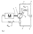
- Fig. 1 shows a schematic representation of an electro-hydraulic pressure supply according to the invention.
- An electric motor M is a drive motor in operative connection with a variable displacement pump 1.
- the electric motor M is in its speed n regulated by a regulator Reg.
- a change in the rotational speed of the electric motor is transmitted via the operative connection 2 to the variable displacement pump 1.
- the control Reg processes as input variables a predetermined value Q soll for the required nominal volume flow and a measured value Q ist for the actual actual volume flow of the variable displacement pump.
- the current volume flow is determined by a device Q for determining the delivered volume flow. The determination of the current volume flow can be obtained directly with a volume flow sensor, or determined indirectly from the reaction of the connected work machine.
- the connecting lines 3 terminate with the load terminals 4.
- one or more hydaulic actuators and one or more hydraulic reservoirs can be connected to the consumer connections 4. Exemplary embodiments for the connection of an actuator are shown in FIGS. 2 to 9.
- the differential pressure Ap between the delivery line and the suction line of the variable displacement pump is detected by a pressure measuring device.
- the differential pressure ⁇ p controls the displacement V of the variable displacement pump.
- the differential pressure ⁇ p and the reference pressure p Ref is input to a control Ctrl.
- the controller Ctrl controls the pump adjustment PV, which is in operative connection with the adjusting member 5 of the variable displacement pump 1.
- a change in the displacement affects the delivered volume flow Q.
- the control Reg fits over the speed n the funded volume flow Q is to the required volume flow Q soll .
- the detection of the volumetric flow can also take place via the determination of the adjusting travel of the adjusting member 5 and the working speed of the variable-displacement pump, for example the rotational speed n.
- the pump operates below a limit torque defined by p Ref as a constant unit with maximum displacement.
- the variation of the electric motor speed n modulates the volume flow (including reversing).
- the control reduces the displacement until the limit torque is applied as a load torque.
- the torque is measured indirectly via the motor current or the differential pressure ⁇ p.
- the requested flow rate Q should be provided at reduced displacement by increasing the engine speed is available.
- Fig. 2 shows a schematic diagram of an embodiment of the invention for reversible Systems with a pump adjustment by an electric actuator.
- a hydraulic actuator 6 and a pressure reservoir 7 are connected to the Pump connections 4, a hydraulic actuator 6 and a pressure reservoir 7 are connected.
- the adjusting member 5 of the variable displacement pump 1 is provided with an electric actuator 8 actuated.
- the actuator is controlled by the control Ctrl.
- Fig. 3 shows a schematic diagram of an embodiment according to the invention for reversible Systems with a pump adjustment by a control piston with pressure control valve.
- a control piston 9 changes the position of the adjusting member. 5 the pump 1.
- the control piston 9 is always connected to the pressure side, which ensures a pressure-controlled 4/3-way valve 10.
- a spring 11 pivots at 0 pressure on the actuator 5 maximum displacement and provides a wegproportionale counterforce under pressure. over an electrically controlled pressure control valve 12, e.g. a pressure control valve, can at Pressurization, the piston force of the control piston 9 can be adjusted.
- the control of the pressure control valve 12 via the control Ctrl. In conjunction with the Spring force of the piston spring 11 results in a piston position.
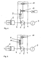
- FIG. 4 shows a schematic illustration of an embodiment according to the invention for reversible Systems with a pump adjustment by a control piston and an electric operated 4-3-way valve.
- a differential control spool changes 9 the position of the actuator 5 of the pump 1.
- An electrically controlled 4/3-way valve 13 ensures the pressurization of the respective piston surface of the differential control piston 9.
- the piston position is over the opening time of the 4/3-way valve 13th regulated.
- the middle position of the valve blocks the oil flow and fixes the piston in his Location.
- the valve is controlled by the control Ctrl.
- a pressure-controlled 4/3-way valve 10 ensures the direction of the control pressure gradient. The dynamics of the adjustment depends on the height of the pressure gradient.
- Fig. 5 shows a schematic diagram of an embodiment of the invention for reversible systems with a pump adjustment by a system horrbeetzschlagten control piston with spring.
- a control piston 9 changes the position of the actuator 5 of the pump 1.
- the control piston 9 is always connected via the terminals 4 and through the 4/3 way valve 10 to the pressure side.
- a spring 11 pivots at 0 pressure the actuator 5 to maximum displacement and provides under pressure a wegproportionale drag.
- the travel of the actuating piston is proportional to the applied pressure gradient. If the spring 11 is installed with prestressing, the system only regulates when a limiting pressure gradient p ref .
- the limiting pressure gradient p Ref is predetermined by the bias of the spring 11.
- the parallel connection of different length and / or different stiffness springs 11 or the use of stepped piston change the control characteristic of the control piston 9. Since the load torque is approximately proportional to pressure, the differential pressure Ap between the two terminals 4 can be used as a control variable.
- the advantage of this embodiment lies in its passive self-regulation by the spring 11. An active regulation of the control piston 9 by an active control can be dispensed with.
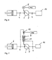
- Fig. 6 shows a schematic diagram of an embodiment of the invention for not reversible systems with a pump adjustment by an electric actuator.
- the Pump 1 not reversible.
- the Reservoir 14 is not a pressure reservoir, but only an unpressurized reservoir for the hydraulic fluid for actuating the hydraulic actuator 6.
- the adjusting member 5 of the pump 1 is actuated by the electric actuator 8.
- the actuator 8 is controlled by the control Ctrl.
- Fig. 7 shows a schematic diagram of an embodiment of the invention for not reversible systems with a pump adjustment by a control piston with pressure control valve.
- a control piston changes, as Figure 11 shows, the position of the adjusting of the Pump.
- the control piston 9 is connected via the pump connection 4 to the pressure side of the pump 1 connected.
- a spring 11 pivots at 0 pressure, the actuator 5 of the pump 1 to a maximum Suction volume and provides a wegproportionale counterforce under pressure.
- About an electric controlled pressure control valve 12, e.g. a pressure control valve, can when pressurized the piston force can be adjusted.
- the control of the valve via the Control Ctrl. In conjunction with the spring force results in the piston position.
- Fig. 8 shows a schematic diagram of an embodiment of the invention for not reversible systems with a pump adjustment by a control piston and an electric operated 4-3-way valve.
- a differential changes Control piston 9, the position of the actuator 5 of the pump 1.
- An electrically controlled 4/3-way valve 13 ensures the pressurization of the respective piston surface.
- the piston position is controlled by the opening time of the valve 13.
- the middle position of the valve locks the oil flow and fixes the piston in its position.
- the control of the valve takes place via the control Ctrl.
- the dynamics of the adjustment depends on the height of the pressure gradient between the two terminals 4 from.
- Fig. 9 shows a schematic diagram of an embodiment according to the invention for non-reversible systems with a pump adjustment by a system horrbeetzschlagten piston with spring.
- a control piston 9 changes the position of the actuator 5 of the pump 1.
- the control piston 9 is connected to the pressure side of the pump 1.
- a spring 11 pivots at 0 pressure the actuator 5 to maximum displacement and provides under pressure a wegproportionale drag.
- the path of the actuating piston corresponds to the applied pressure gradient. If the spring 11 is installed with prestressing, the system only regulates when a limiting pressure gradient p ref .
- the limiting pressure gradient p Ref is predetermined by the bias of the spring 11.
Landscapes
- Engineering & Computer Science (AREA)
- Mechanical Engineering (AREA)
- General Engineering & Computer Science (AREA)
- Control Of Positive-Displacement Pumps (AREA)
- Fluid-Pressure Circuits (AREA)
- Control Of Non-Positive-Displacement Pumps (AREA)
- Reciprocating Pumps (AREA)
Description
- Fig.1
- Eine schematische Darstellung der erfindungsgemäßen Elektrohydraulischen Druckversorgung.
- Fig. 2
- Eine Prinzipdarstellung eines erfindungsgemäßen Ausführungsbeispiels für reversierbare Systeme mit einer Pumpenverstellung durch einen elektrischen Aktuator
- Fig. 3
- Eine Prinzipdarstellung eines erfindungsgemäßen Ausführungsbeispiels für reversierbare Systeme mit einer Pumpenverstellung durch einen Steuerkolben mit Druckregelventil
- Fig. 4
- Eine Prinzipdarstellung eines erfindungsgemäßen Ausführungsbeispiels für reversierbare Systeme mit einer Pumpenverstellung durch einen Steuerkolben und ein elektrisch betätigtes 4-3-Wege-Ventil
- Fig. 5
- Eine Prinzipdarstellung eines erfindungsgemäßen Ausführungsbeispiels für reversierbare Systeme mit einer Pumpenverstellung durch einen systemdruckbeaufschlagten Steuerkolben mit Feder
- Fig. 6
- Eine Prinzipdarstellung eines erfindungsgemäßen Ausführungsbeispiels für nicht reversierbare Systeme mit einer Pumpenverstellung durch einen elektrischen Aktuator
- Fig. 7
- Eine Prinzipdarstellung eines erfindungsgemäßen Ausführungsbeispiels für nicht reversierbare Systeme mit einer Pumpenverstellung durch einen Steuerkolben mit Druckregelventil
- Fig. 8
- Eine Prinzipdarstellung eines erfindungsgemäßen Ausführungsbeispiels für nicht reversierbare Systeme mit einer Pumpenverstellung durch einen Steuerkolben und elektrisch betätigtes 4-3-Wege-Ventil
- Fig. 9
- Eine Prinzipdarstellung eines erfindungsgemäßen Ausführungsbeispiels für nicht reversierbare Systeme mit einer Pumpenverstellung durch einen systemdruckbeaufschlagten Kolben mit Feder
Claims (11)
- Elektrohydraulische Druckversorgung mit einem drehzahlregelbaren elektrischen Antriebsmotor (M) und einer Verstellpumpe (1), deren Schluckvolumen (V) durch ein Verstellglied (5) veränderbar ist, und mit zwei Anschlußleitungen (3) von der Verstellpumpe (1) zu den Verbraucheranschlüssen (4) umfassendeine Regelung (Reg) zur Drehzahlregelung des Antriebsmotors (M) und einer Einrichtung (Q) zur Bestimmung des geförderten Volumenstroms (Qist), wobei die Regelung (Reg) mindestens den geförderten Volumenstrom (Qist) und einen Sollvolumenstrom (Qsoll) als Eingangsgrößen hat,eine Pumpenverstellung (PV) zur Betätigung des Verstellgliedes (5) der Verstellpumpe (1) und einer Steuerung (Strg) zur Ansteuerung der Pumpenverstellung (PV) und einer Druckmeßeinrichtung zur Bestimmung des Differenzdrucks (Δp) zwischen den beiden Anschlußleitungen (3), wobei die Steuerung (Strg) das Schluckvolumen (V) abhängig von einem das Grenzmoment der Verstellpumpe angebenden Referenzdruck (pRef) und dem Differenzdruck (Δp) mittels der Pumpenverstellung (PV) einstellt, und wobei die Regelung (Reg) das Schluckvolumen (V) verringert, wenn das Lastmoment der Verstellpumpe (1) das Grenzmoment überschreitet, derart, daß das als Lastmoment das Grenzmoment anliegt.
- Vorrichtung nach Anspruch 1, dadurch gekennzeichnet, daß die Drehzahl (n) des Antriebsmotor (M) im wesentlichen unabhänhig von der Verstellung des Schluckvolumens (V) der Verstellpumpe (1) einstellbar ist.
- Vorrichtung nach Anspruch 1 oder 2, dadurch gekennzeichnet, daß die Verstellpumpe (1) als Einrichtung zur Drehmomentbeeinflussung für den Antriebsmotor (M) betreibbar ist.
- Vorrichtung nach einem der Ansprüche 1 bis 3 für reversierbare Systeme mit einem hydraulischen Aktor (6) und einem Druckvorratbehälter (7), dadurch gekennzeichnet, daß die Pumpenverstellung (PV) ein elektrischer Aktuator (8) ist.
- Vorrichtung nach einem der Ansprüche 1 bis 3 für reversierbare Systeme mit einem hydraulischen Aktor (6) und einem Druckvorratbehälter (7), dadurch gekennzeichnet, daß die Pumpenverstellung (PV) aus einem Ventil zur Druckregelung (12) , einem Steuerkolben (9) mit mindestens einer Feder (11) und einem hydraulisch betätigten 4-3-Wege-Ventil (10) besteht.
- Vorrichtung nach einem der Ansprüche 1 bis 3 für reversierbare Systeme mit einem hydraulischen Aktor (6) und einem Druckvorratbehälter (7), dadurch gekennzeichnet, daß die Pumpenverstellung (PV) aus einem Differentialsteuerkolben (9), einem hydraulisch betätigten 4-3-Wege-Ventil (10) und einem elektrisch betätigten 4-3-Wege-Ventil 13 besteht.
- Vorrichtung nach einem der Ansprüche 1 bis 3 für reversierbare Systeme mit einem hydraulischen Aktor (6) und einem Druckvorratbehälter (7), dadurch gekennzeichnet, daß die Pumpenverstellung (PV) aus einem Steuerkolben (9) mit mindestens einer Feder (11) und einem hydraulisch betätigten 4-3-Wegeventil (10) besteht.
- Vorrichtung nach einem der Ansprüche 1 bis 3 für nicht-reversierbare Syteme mit einem hydraulischen Aktor (6) und einem Vorratsbehälter (14), dadurch gekennzeichnet, daß die Pumpenverstellung (PV) ein elektrischer Aktuator (8) ist.
- Vorrichtung nach einem der Ansprüche 1 bis 3 für nicht-reversierbare Syteme mit einem hydraulischen Aktor (6) und einem Vorratsbehälter (14), dadurch gekennzeichnet, daß die Pumpenverstellung (PV) aus einem Ventil zur Druckregelung (12) und einem Steuerkolben (9) mit mindestens einer Feder (11) besteht.
- Vorrichtung nach einem der Ansprüche 1 bis 3 für nicht-reversierbare Syteme mit einem hydraulischen Aktor (6) und einem Vorratsbehälter (14), dadurch gekennzeichnet, daß die Pumpenverstellung (PV) aus einem Differentialsteuerkolben (9) und einem elektrisch betätigten 4-3-Wege-Ventil (13) besteht.
- Vorrichtung nach einem der Ansprüche 1 bis 3 für nicht-reversierbare Syteme mit einem hydraulischen Aktor (6) und einem Vorratsbehälter (14), dadurch gekennzeichnet, daß die Pumpenverstellung (PV) aus einem Steuerkolben (9) mit mindestens einer Feder (11) besteht.
Applications Claiming Priority (2)
| Application Number | Priority Date | Filing Date | Title |
|---|---|---|---|
| DE19930648A DE19930648A1 (de) | 1999-07-02 | 1999-07-02 | Elektrohydraulische Druckversorgung mit verstellbarer Pumpe und regelbarem elektrischem Antrieb |
| DE19930648 | 1999-07-02 |
Publications (3)
| Publication Number | Publication Date |
|---|---|
| EP1065379A2 EP1065379A2 (de) | 2001-01-03 |
| EP1065379A3 EP1065379A3 (de) | 2002-06-12 |
| EP1065379B1 true EP1065379B1 (de) | 2004-03-10 |
Family
ID=7913492
Family Applications (1)
| Application Number | Title | Priority Date | Filing Date |
|---|---|---|---|
| EP00110414A Expired - Lifetime EP1065379B1 (de) | 1999-07-02 | 2000-05-16 | Elektrohydraulische Druckversorgung mit verstellbarer Pumpe und regelbarem elektrischem Antrieb |
Country Status (5)
| Country | Link |
|---|---|
| US (1) | US6347516B1 (de) |
| EP (1) | EP1065379B1 (de) |
| JP (1) | JP2001041167A (de) |
| AT (1) | ATE261546T1 (de) |
| DE (2) | DE19930648A1 (de) |
Families Citing this family (19)
| Publication number | Priority date | Publication date | Assignee | Title |
|---|---|---|---|---|
| DE10158341B4 (de) * | 2000-12-07 | 2010-11-18 | Ixetic Bad Homburg Gmbh | Pumpe für Fahrwerksysteme |
| DE10104635A1 (de) * | 2001-02-02 | 2002-10-02 | Joma Hydromechanic Gmbh | Verfahren zum Aufrechterhalten einer konstanten Ausgangsgröße einer Förderpumpe, z.B. ihres Fördervolumens, die von einer in ihrer Drehzahl variablen Antriebsvorrichtung angetrieben wird, sowie Vorrichtung zur Durchführung des Verfahrens |
| DE10307190A1 (de) * | 2003-02-20 | 2004-09-16 | O & K Orenstein & Koppel Gmbh | Verfahren zur Steuerung eines Hydrauliksystems einer mobilen Arbeitsmaschine |
| DE102005023430A1 (de) * | 2005-03-15 | 2006-09-21 | Fresenius Medical Care Deutschland Gmbh | Verfahren und Vorrichtung zur Bestimmung der effektiven Förderrate oder Einstellung der Drehzahl einer peristaltischen Pumpe |
| DE102007007005B4 (de) | 2007-02-08 | 2021-12-02 | Robert Bosch Gmbh | Elektrohydraulische Steueranordnung |
| US20110176940A1 (en) * | 2008-07-08 | 2011-07-21 | Ellis Shawn D | High pressure intensifier system |
| DE102009021866A1 (de) * | 2009-05-19 | 2010-11-25 | Sauer-Danfoss Gmbh & Co Ohg | Hydroantrieb mit einer unabhängigen Speisepumpe |
| US9222575B2 (en) * | 2010-12-22 | 2015-12-29 | Gm Global Technology Operations, Llc | Electric pump |
| US9062665B2 (en) * | 2013-01-15 | 2015-06-23 | Husco International, Inc. | Hydraulic piston pump with throttle control |
| DE102013005774B4 (de) * | 2013-04-05 | 2021-01-21 | Robert Bosch Gmbh | Nutzung einer von einem motor angetriebenen drehzahlvariablen hydraulikpumpe als hydrostatisches getriebe |
| US20160252080A1 (en) | 2013-12-18 | 2016-09-01 | Schaeffler Technologies AG & Co. KG | Variable displacement pump |
| US20170138417A1 (en) * | 2014-03-24 | 2017-05-18 | Schaeffler Technologies AG & Co. KG | Actuator which can be drive-coupled and has a variable displacement pump |
| DE102015209951A1 (de) * | 2015-05-29 | 2016-12-01 | Zf Friedrichshafen Ag | Ölfördersystem eines Kraftfahrzeugs |
| SE544986C2 (en) * | 2019-04-05 | 2023-02-21 | Epiroc Rock Drills Ab | Method and system for controlling operation of a hydraulic system of a drilling rig |
| CN112983798B (zh) * | 2021-03-25 | 2023-02-24 | 烟台杰瑞石油装备技术有限公司 | 应用于电驱压裂设备的控制方法及其控制装置 |
| DE102022203051B3 (de) | 2022-03-29 | 2023-10-12 | Robert Bosch Gesellschaft mit beschränkter Haftung | Verfahren zum Betreiben einer drehzahlvariablen Pumpe |
| CN116161109B (zh) * | 2023-02-28 | 2024-06-11 | 中国重汽集团济南动力有限公司 | 一种转向泵控制策略实现方法、装置及存储介质 |
| DE102023203371A1 (de) * | 2023-04-13 | 2024-10-17 | Robert Bosch Gesellschaft mit beschränkter Haftung | Verfahren zur Verringerung von Leistungsverlusten in einem elektrohydraulischen System |
| US20250389260A1 (en) * | 2024-06-21 | 2025-12-25 | Hamilton Sundstrand Corporation | Pwm control of actuation pressure for variable-displacement hydraulic pumps |
Family Cites Families (6)
| Publication number | Priority date | Publication date | Assignee | Title |
|---|---|---|---|---|
| US4600364A (en) * | 1983-06-20 | 1986-07-15 | Kabushiki Kaisha Komatsu Seisakusho | Fluid operated pump displacement control system |
| DE3780292T2 (de) * | 1986-08-15 | 1993-01-07 | Komatsu Mfg Co Ltd | Steuerungseinheit einer hydraulischen pumpe. |
| US4930992A (en) * | 1987-07-09 | 1990-06-05 | Tokyo Keiki Company Ltd. | Control apparatus of variable delivery pump |
| US5170625A (en) * | 1989-07-27 | 1992-12-15 | Hitachi Construction Machinery Co., Ltd. | Control system for hydraulic pump |
| US5638677A (en) * | 1991-03-29 | 1997-06-17 | Hitachi Construction Machinery Co., Ltd. | Control device for hydraulically propelled work vehicle |
| US5307288A (en) * | 1991-06-07 | 1994-04-26 | Haines Lawrence A | Unitary fluid flow production and control system |
-
1999
- 1999-07-02 DE DE19930648A patent/DE19930648A1/de not_active Withdrawn
-
2000
- 2000-05-16 DE DE50005576T patent/DE50005576D1/de not_active Expired - Fee Related
- 2000-05-16 EP EP00110414A patent/EP1065379B1/de not_active Expired - Lifetime
- 2000-05-16 AT AT00110414T patent/ATE261546T1/de not_active IP Right Cessation
- 2000-06-29 JP JP2000196981A patent/JP2001041167A/ja active Pending
- 2000-06-30 US US09/607,963 patent/US6347516B1/en not_active Expired - Fee Related
Also Published As
| Publication number | Publication date |
|---|---|
| DE50005576D1 (de) | 2004-04-15 |
| JP2001041167A (ja) | 2001-02-13 |
| US6347516B1 (en) | 2002-02-19 |
| ATE261546T1 (de) | 2004-03-15 |
| EP1065379A3 (de) | 2002-06-12 |
| DE19930648A1 (de) | 2001-01-11 |
| EP1065379A2 (de) | 2001-01-03 |
Similar Documents
| Publication | Publication Date | Title |
|---|---|---|
| EP1065379B1 (de) | Elektrohydraulische Druckversorgung mit verstellbarer Pumpe und regelbarem elektrischem Antrieb | |
| EP2121280B1 (de) | Elektrohydraulische steueranordnung | |
| DE1949687A1 (de) | Hydrostatische Kraftuebertragung mit Drucksteuerung | |
| DE19852039A1 (de) | Hydrostatisch angetriebenes Fahrzeug mit Retarderventileinrichtung | |
| EP1567403B1 (de) | Hydraulische lenkung für fahrzeuge | |
| EP1356208A1 (de) | Pumpsystem mit einer hydraulischen pumpe, insbesondere für ein lenksystem | |
| EP0262471B1 (de) | Hydrauliksystem mit zwei doppelseitig beaufschlagbaren Verbrauchern, einer Dosierpumpe und einer an einen Sammelbehälter angeschlossenen Pumpe | |
| EP0273214B1 (de) | Regeleinrichtung für eine verstellbare hydrostatische Maschine | |
| EP1222416B1 (de) | Steuerventileinheit für einen hydraulischen aufzug | |
| EP2049800A1 (de) | Förderpumpe | |
| DE19509869B4 (de) | Steuer- und Regelsystem für ein automotives hydrostatisches Getriebe | |
| EP0797727A1 (de) | Hydraulikanlage fur ein kraftfahrzeug | |
| DE3711233A1 (de) | Antriebseinrichtung mit einer primaerenergiequelle, einem getriebe und einer pumpe | |
| EP0574737B1 (de) | Fahrzeug mit batterie-elektrischem Antrieb, insbesondere Hublader | |
| DE4136813C2 (de) | Arbeitsflüssigkeits-Kreislauf für einen Regelkreis einer aktiven Radaufhängung eines Fahrzeugs | |
| EP1178943A1 (de) | Einrichtung zum steuern der neigenfunktion eines hubmastes, insbesondere für einen gabelstapler | |
| WO1996018809A1 (de) | Hydraulikanlage fur ein kraftfahrzeug | |
| DE10065367C2 (de) | Regelung der Drehzahl eines hydrostatischen Motors | |
| DE2818452A1 (de) | Fahrzeug mit einer zwischen den hauptmotor und die fortbewegungsorgane eingeschalteten hydrostatischen kraftuebertragung | |
| DE3728207A1 (de) | Ventilanordnung fuer zwei von einem gemeinsamen antrieb angetriebene leistungsgeregelte pumpen | |
| EP0456175B1 (de) | Hydrostatisches Antriebssystem für Fahrzeuge | |
| WO2022248367A1 (de) | Verfahren zur steuerung eines hydrostatischen antriebs | |
| EP2955059B1 (de) | Hydraulisches kippsystem mit einer den senkbetrieb unterstützenden pumpe | |
| DE102004006417A1 (de) | Hydraulische Lenkung mit Druckspeicher und geregelter Pumpe | |
| DE202004008847U1 (de) | Hydraulische Lenkung mit geregelter Pumpe |
Legal Events
| Date | Code | Title | Description |
|---|---|---|---|
| PUAI | Public reference made under article 153(3) epc to a published international application that has entered the european phase |
Free format text: ORIGINAL CODE: 0009012 |
|
| 17P | Request for examination filed |
Effective date: 20000516 |
|
| AK | Designated contracting states |
Kind code of ref document: A2 Designated state(s): AT BE CH CY DE DK ES FI FR GB GR IE IT LI LU MC NL PT SE |
|
| AX | Request for extension of the european patent |
Free format text: AL;LT;LV;MK;RO;SI |
|
| PUAL | Search report despatched |
Free format text: ORIGINAL CODE: 0009013 |
|
| RIC1 | Information provided on ipc code assigned before grant |
Free format text: 7F 04B 49/06 A, 7F 04B 49/20 B, 7F 04B 49/08 B |
|
| AK | Designated contracting states |
Kind code of ref document: A3 Designated state(s): AT BE CH CY DE DK ES FI FR GB GR IE IT LI LU MC NL PT SE |
|
| AX | Request for extension of the european patent |
Free format text: AL;LT;LV;MK;RO;SI |
|
| 17Q | First examination report despatched |
Effective date: 20030102 |
|
| AKX | Designation fees paid |
Designated state(s): AT BE CH CY DE DK ES FI FR GB GR IE IT LI LU MC NL PT SE |
|
| REG | Reference to a national code |
Ref country code: GB Ref legal event code: FG4D Free format text: NOT ENGLISH |
|
| GRAP | Despatch of communication of intention to grant a patent |
Free format text: ORIGINAL CODE: EPIDOSNIGR1 |
|
| GRAS | Grant fee paid |
Free format text: ORIGINAL CODE: EPIDOSNIGR3 |
|
| GRAA | (expected) grant |
Free format text: ORIGINAL CODE: 0009210 |
|
| AK | Designated contracting states |
Kind code of ref document: B1 Designated state(s): AT BE CH CY DE DK ES FI FR GB GR IE IT LI LU MC NL PT SE |
|
| PG25 | Lapsed in a contracting state [announced via postgrant information from national office to epo] |
Ref country code: IT Free format text: LAPSE BECAUSE OF FAILURE TO SUBMIT A TRANSLATION OF THE DESCRIPTION OR TO PAY THE FEE WITHIN THE PRESCRIBED TIME-LIMIT;WARNING: LAPSES OF ITALIAN PATENTS WITH EFFECTIVE DATE BEFORE 2007 MAY HAVE OCCURRED AT ANY TIME BEFORE 2007. THE CORRECT EFFECTIVE DATE MAY BE DIFFERENT FROM THE ONE RECORDED. Effective date: 20040310 Ref country code: NL Free format text: LAPSE BECAUSE OF FAILURE TO SUBMIT A TRANSLATION OF THE DESCRIPTION OR TO PAY THE FEE WITHIN THE PRESCRIBED TIME-LIMIT Effective date: 20040310 Ref country code: CY Free format text: LAPSE BECAUSE OF FAILURE TO SUBMIT A TRANSLATION OF THE DESCRIPTION OR TO PAY THE FEE WITHIN THE PRESCRIBED TIME-LIMIT Effective date: 20040310 Ref country code: IE Free format text: LAPSE BECAUSE OF FAILURE TO SUBMIT A TRANSLATION OF THE DESCRIPTION OR TO PAY THE FEE WITHIN THE PRESCRIBED TIME-LIMIT Effective date: 20040310 Ref country code: FI Free format text: LAPSE BECAUSE OF FAILURE TO SUBMIT A TRANSLATION OF THE DESCRIPTION OR TO PAY THE FEE WITHIN THE PRESCRIBED TIME-LIMIT Effective date: 20040310 |
|
| REG | Reference to a national code |
Ref country code: CH Ref legal event code: EP |
|
| REG | Reference to a national code |
Ref country code: IE Ref legal event code: FG4D Free format text: GERMAN |
|
| REF | Corresponds to: |
Ref document number: 50005576 Country of ref document: DE Date of ref document: 20040415 Kind code of ref document: P |
|
| PG25 | Lapsed in a contracting state [announced via postgrant information from national office to epo] |
Ref country code: AT Free format text: LAPSE BECAUSE OF NON-PAYMENT OF DUE FEES Effective date: 20040516 Ref country code: LU Free format text: LAPSE BECAUSE OF NON-PAYMENT OF DUE FEES Effective date: 20040516 |
|
| PG25 | Lapsed in a contracting state [announced via postgrant information from national office to epo] |
Ref country code: MC Free format text: LAPSE BECAUSE OF NON-PAYMENT OF DUE FEES Effective date: 20040531 Ref country code: BE Free format text: LAPSE BECAUSE OF NON-PAYMENT OF DUE FEES Effective date: 20040531 Ref country code: CH Free format text: LAPSE BECAUSE OF NON-PAYMENT OF DUE FEES Effective date: 20040531 Ref country code: LI Free format text: LAPSE BECAUSE OF NON-PAYMENT OF DUE FEES Effective date: 20040531 |
|
| PG25 | Lapsed in a contracting state [announced via postgrant information from national office to epo] |
Ref country code: SE Free format text: LAPSE BECAUSE OF FAILURE TO SUBMIT A TRANSLATION OF THE DESCRIPTION OR TO PAY THE FEE WITHIN THE PRESCRIBED TIME-LIMIT Effective date: 20040610 Ref country code: GR Free format text: LAPSE BECAUSE OF FAILURE TO SUBMIT A TRANSLATION OF THE DESCRIPTION OR TO PAY THE FEE WITHIN THE PRESCRIBED TIME-LIMIT Effective date: 20040610 Ref country code: DK Free format text: LAPSE BECAUSE OF FAILURE TO SUBMIT A TRANSLATION OF THE DESCRIPTION OR TO PAY THE FEE WITHIN THE PRESCRIBED TIME-LIMIT Effective date: 20040610 |
|
| PG25 | Lapsed in a contracting state [announced via postgrant information from national office to epo] |
Ref country code: ES Free format text: LAPSE BECAUSE OF FAILURE TO SUBMIT A TRANSLATION OF THE DESCRIPTION OR TO PAY THE FEE WITHIN THE PRESCRIBED TIME-LIMIT Effective date: 20040621 |
|
| GBT | Gb: translation of ep patent filed (gb section 77(6)(a)/1977) |
Effective date: 20040603 |
|
| NLV1 | Nl: lapsed or annulled due to failure to fulfill the requirements of art. 29p and 29m of the patents act | ||
| REG | Reference to a national code |
Ref country code: IE Ref legal event code: FD4D |
|
| ET | Fr: translation filed | ||
| BERE | Be: lapsed |
Owner name: DAIMLERCHRYSLER A.G. Effective date: 20040531 |
|
| PLBE | No opposition filed within time limit |
Free format text: ORIGINAL CODE: 0009261 |
|
| REG | Reference to a national code |
Ref country code: CH Ref legal event code: PL |
|
| STAA | Information on the status of an ep patent application or granted ep patent |
Free format text: STATUS: NO OPPOSITION FILED WITHIN TIME LIMIT |
|
| 26N | No opposition filed |
Effective date: 20041213 |
|
| PGFP | Annual fee paid to national office [announced via postgrant information from national office to epo] |
Ref country code: GB Payment date: 20050510 Year of fee payment: 6 |
|
| PGFP | Annual fee paid to national office [announced via postgrant information from national office to epo] |
Ref country code: FR Payment date: 20050512 Year of fee payment: 6 |
|
| PG25 | Lapsed in a contracting state [announced via postgrant information from national office to epo] |
Ref country code: GB Free format text: LAPSE BECAUSE OF NON-PAYMENT OF DUE FEES Effective date: 20060516 |
|
| GBPC | Gb: european patent ceased through non-payment of renewal fee |
Effective date: 20060516 |
|
| REG | Reference to a national code |
Ref country code: FR Ref legal event code: ST Effective date: 20070131 |
|
| PG25 | Lapsed in a contracting state [announced via postgrant information from national office to epo] |
Ref country code: PT Free format text: LAPSE BECAUSE OF NON-PAYMENT OF DUE FEES Effective date: 20040810 |
|
| PG25 | Lapsed in a contracting state [announced via postgrant information from national office to epo] |
Ref country code: FR Free format text: LAPSE BECAUSE OF NON-PAYMENT OF DUE FEES Effective date: 20060531 |
|
| PGFP | Annual fee paid to national office [announced via postgrant information from national office to epo] |
Ref country code: DE Payment date: 20090525 Year of fee payment: 10 |
|
| PG25 | Lapsed in a contracting state [announced via postgrant information from national office to epo] |
Ref country code: DE Free format text: LAPSE BECAUSE OF NON-PAYMENT OF DUE FEES Effective date: 20101201 |