EP1065423B1 - Rohrkupplung - Google Patents
Rohrkupplung Download PDFInfo
- Publication number
- EP1065423B1 EP1065423B1 EP00111971A EP00111971A EP1065423B1 EP 1065423 B1 EP1065423 B1 EP 1065423B1 EP 00111971 A EP00111971 A EP 00111971A EP 00111971 A EP00111971 A EP 00111971A EP 1065423 B1 EP1065423 B1 EP 1065423B1
- Authority
- EP
- European Patent Office
- Prior art keywords
- small
- screw portion
- retainer
- disc
- female screw
- Prior art date
- Legal status (The legal status is an assumption and is not a legal conclusion. Google has not performed a legal analysis and makes no representation as to the accuracy of the status listed.)
- Expired - Lifetime
Links
- 230000002093 peripheral effect Effects 0.000 claims description 29
- 239000000565 sealant Substances 0.000 description 6
- 238000010276 construction Methods 0.000 description 3
- 241001236644 Lavinia Species 0.000 description 2
- 230000037431 insertion Effects 0.000 description 2
- 238000003780 insertion Methods 0.000 description 2
- 239000002184 metal Substances 0.000 description 2
- 229910052751 metal Inorganic materials 0.000 description 2
- RYGMFSIKBFXOCR-UHFFFAOYSA-N Copper Chemical compound [Cu] RYGMFSIKBFXOCR-UHFFFAOYSA-N 0.000 description 1
- 229910000760 Hardened steel Inorganic materials 0.000 description 1
- 235000008331 Pinus X rigitaeda Nutrition 0.000 description 1
- 235000011613 Pinus brutia Nutrition 0.000 description 1
- 241000018646 Pinus brutia Species 0.000 description 1
- 239000011324 bead Substances 0.000 description 1
- 239000000919 ceramic Substances 0.000 description 1
- 229910052802 copper Inorganic materials 0.000 description 1
- 239000010949 copper Substances 0.000 description 1
- 230000001419 dependent effect Effects 0.000 description 1
- 230000005489 elastic deformation Effects 0.000 description 1
- 230000003628 erosive effect Effects 0.000 description 1
- 239000012530 fluid Substances 0.000 description 1
- 230000008595 infiltration Effects 0.000 description 1
- 238000001764 infiltration Methods 0.000 description 1
- 239000007788 liquid Substances 0.000 description 1
- 238000000465 moulding Methods 0.000 description 1
- 238000007789 sealing Methods 0.000 description 1
- 229910001220 stainless steel Inorganic materials 0.000 description 1
- 239000010935 stainless steel Substances 0.000 description 1
- XLYOFNOQVPJJNP-UHFFFAOYSA-N water Substances O XLYOFNOQVPJJNP-UHFFFAOYSA-N 0.000 description 1
Images




Classifications
-
- F—MECHANICAL ENGINEERING; LIGHTING; HEATING; WEAPONS; BLASTING
- F16—ENGINEERING ELEMENTS AND UNITS; GENERAL MEASURES FOR PRODUCING AND MAINTAINING EFFECTIVE FUNCTIONING OF MACHINES OR INSTALLATIONS; THERMAL INSULATION IN GENERAL
- F16L—PIPES; JOINTS OR FITTINGS FOR PIPES; SUPPORTS FOR PIPES, CABLES OR PROTECTIVE TUBING; MEANS FOR THERMAL INSULATION IN GENERAL
- F16L19/00—Joints in which sealing surfaces are pressed together by means of a member, e.g. a swivel nut, screwed on, or into, one of the joint parts
- F16L19/08—Joints in which sealing surfaces are pressed together by means of a member, e.g. a swivel nut, screwed on, or into, one of the joint parts with metal rings which bite into the wall of the pipe
- F16L19/083—Joints in which sealing surfaces are pressed together by means of a member, e.g. a swivel nut, screwed on, or into, one of the joint parts with metal rings which bite into the wall of the pipe the longitudinal cross-section of the ring not being modified during clamping
- F16L19/086—Joints in which sealing surfaces are pressed together by means of a member, e.g. a swivel nut, screwed on, or into, one of the joint parts with metal rings which bite into the wall of the pipe the longitudinal cross-section of the ring not being modified during clamping with additional sealing means
-
- F—MECHANICAL ENGINEERING; LIGHTING; HEATING; WEAPONS; BLASTING
- F16—ENGINEERING ELEMENTS AND UNITS; GENERAL MEASURES FOR PRODUCING AND MAINTAINING EFFECTIVE FUNCTIONING OF MACHINES OR INSTALLATIONS; THERMAL INSULATION IN GENERAL
- F16L—PIPES; JOINTS OR FITTINGS FOR PIPES; SUPPORTS FOR PIPES, CABLES OR PROTECTIVE TUBING; MEANS FOR THERMAL INSULATION IN GENERAL
- F16L15/00—Screw-threaded joints; Forms of screw-threads for such joints
Definitions
- This invention relates to a pipe joint.
- an end of a connected pipe is cut to be a tapered male screw portion to which a female screw portion of a pipe joint is screwed.
- Pine joints with an uncut, i.e. smooth end of the connected pipe are also known in the art, as disclosed EP-A-0 327 080, US-A-2 127 284 or US-A- 1 711 995, for example.
- the fixation of the uncut, i.e. smooth end of the connected pipe to the joint main body is often weak and unsatisfactory.
- FIG. 1 shows a preferred embodiment of the present invention.
- This pipe joint is provided with a joint main body 1 having a female screw portion 6 on which a tapered female screw portion 6a is formed on an opening end, a cylindrical retainer 2 having a (tapered) male screw portion 7 which screws into the female screw portion 6 (the tapered female screw portion 6a) of the joint main body 1, and a sealant 3.
- the retainer 2 has plural small-disc continuous bodies 31 each of which is composed of two or three small discs 4 for pipe fixation embedded in the male screw portion 7 as that a part of the small disc 4 protrudes from a peripheral side along the thread of the male screw portion 7 and another part of the small disc 4 protrudes from an inner peripheral face 8.
- the cylindrical joint main body 1 has the female screw portion 6, a parallel portion for sealing 9, a first stepped portion 10, a connected pipe insertion portion 11, a second stepped portion 12, and a duct hole 13, in this order in an axis K direction starting with an open end of the main body 1.
- the first stepped portion 10 is arranged to be circular, and a ring of the sealant 3 is placed between the first stepped portion 10 and the parallel portion 9.
- the retainer 2 made of plastic has the above male screw portion 7 on a peripheral face of a cylinder portion 14 and a polygonal outer brim portion 15 on a base end of the cylinder portion 14.
- the small-disc continuous body 31 is composed of two connected small discs 4.
- the small disc 4 is made of metal (hardened steel or stainless steel, for example), hexagonal in front view as shown in Figure 2A, and circular in side view as shown in Figure 2B.
- External configuration of the small disc 4 is a bead of an abacus having a sharp circular peripheral edge 18 and circular plane portions 20 raised on both sides of the circular peripheral edge 18.
- the small-disc continuous body 31 is formed by connecting two small discs 4 as the circular plane portions 20 are fitted each other.
- cross-sectional configuration of an outside peak portion 16 of the small disc 4 of the small-disc continuous body 31 is formed to be approximately same as that of a ridge portion 17 of the male screw portion 7. That is to say, an angle ⁇ of the outside peak portion 16 of the small disc 4 is set to be approximately same as screw angle of the male screw portion 7 (an angle of a peak portion 17a of the ridge portion 17), and the outside peak portion 16 forms a part of the peak portion 17a of the ridge portion 17.
- the small-disc continuous body 31 is formed as to screws to the female screw portion 6 of the joint main body 1 between the connected plural (two) small discs 4. Strength of screwed connection between the retainer 2 and the joint main body 1 is kept thereby.
- the hole portion 19 of the retainer 2 has an outer opening portion 28 for protrusion of outside peak portions 16 of the small-disc continuous body 31 on a peripheral side and an inner opening portion 29 for protrusion of inside peak portions 25 on an inner peripheral side.
- Inside of the hole portion 19 is formed to be wider than the outer opening portion 28 and the inner opening portion 29, and surrounding the (above described) circular plane portions 20 of the small-disc continuous body 31.
- the outer opening portion 28 is wider than the inner opening portion 29, and an opening edge 21 is rounded.
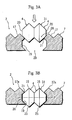
- Figure 3A shows a state before press-fitting of the small-disc continuous body 31 to the hole portion 19 of the retainer 2.
- the small-disc continuous body 31 is pressed to the hole portion 19 side from the outer opening portion 28, the outer opening portion 28 is enlarged by elastic deformation of plastic, the circular plane portions 20 of the small-disc continuous body 31 slide over the opening edge 21 and fit into the inside of the hole portion 19 as shown in Figure 3B, and the small-disc continuous body 31 is embedded into the hole portion 19 as to be able to rotate around an axis P going through the center of the circular plane portions 20.
- the male screw portion 7 of the retainer 2 is screwed to the female screw portion 6 of the joint main body 1, and the retainer 2 is screwed into a gap between the male screw portion 7 of the joint main body 1 and the connected pipe 5 until an end face of the outer brim portion 15 contacts the joint main body 1 as shown in Figure 4.
- the small-disc continuous body 31 is prevented from escaping by the outside peak portions 16 sliding on the female screw portion 6, and the inside peak portions 25, protruding from the inner peripheral face 8 of the retainer 2, can certainly bite into a peripheral face 22 of the connected pipe 5 thereby.
- the inside peak portions 25 of the peripheral edges 18 of first small-disc continuous body 31 (arranged most proximate to the joint main body 1 side) among the small-disc continuous bodies 31 gradually bite into a peripheral face 22 of the connected pipe 5 as the retainer 2 screws into, and form spiral bite traces 23.
- an interrupting small convex portion is on the peripheral face 22, the small-disc continuous body 31 gets over the small convex portion, and the retainer 2 is smoothly screwed until the end.
- an end 24 of the retainer 2 presses the sealant 3 to the first stepped portion 10 side of the joint main body 1, a gap surrounded by the joint main body 1, the connected pipe 5, and the retainer 2 is tightly closed thereby, and leakage of fluid is prevented in use thereafter. And, a worker can visually check accurate screwing and swiftly conduct connecting operation because it is arranged that the sealant 3 is appropriately pressed and the small-disc continuous bodies 31 of the male screw portion 7, which screws into the female screw portion 6, deeply bite into the connected pipe 5 by screwing the retainer 2 until the outer brim portion 15 contacts the joint main body 1.
- the small-disc continuous body 31 can hold a stable position.
- the small-disc continuous body 31 may be composed of three small discs 4 with which the fixation of the connected pipe 5 becomes stronger in comparison with the small-disc continuous body 31 composed of two small discs 4 (shown in Figure 5) in the completed state of the fastening (connection) of the retainer 2 and the joint main body 1 (refer to Figure 4).
- resisting force F 3 is generated on a position of an outer outside peak portion 36 (the nearest to the opening end side of the joint main body 1) among the outside peak portions 16 of the small-disc continuous body 31, and resisting force F 4 is generated on a position of an inner inside peak portion 35 (the nearest to the innermost part of the joint main body 1) among the inside peak portions 15 of the small-disc continuous body 31, and the fixation of the connected pipe 5 becomes strong further.
- radius of rotation in the arrow R 2 direction of which center is the outer outside peak portion 36 of the small-disc continuous body 31 having three small discs 4 is larger than that of two small discs (refer to Figure 5), the inner inside peak portion 35 bites into the bite trace 23 more deeply.
- the resisting force F 3 and F 4 of the three small discs 4 are larger than the resisting force F 1 and F 2 of the two small discs 4 because inclination angle of the imaginary line L 2 of the three small discs 4 to the connected pipe 5 is smaller than that of the imaginary line L 1 of the two small discs 4 (refer to Figure 5), and the fixation of the connected pipe 5 becomes strong further.
- the small-disc continuous body 31 can keep a further stable position.
- the small-disc continuous body 31 is composed of one small disc 4, as shown in Figure 7A, when drawing force in an arrow G 3 direction (parting from the joint main body 1) works on the connected pipe 5 in a completed state of fastening (connection) of the retainer 2 and the joint main body 1 (refer to Figure 4), rotational force in an arrow R 3 direction around the outside peak portion 16 as a center works on the small-disc continuous body 31. And, the small-disc continuous body 31 topples down and the inside peak portion 25 goes out of the bite trace 23 as shown in Figure 7B because resisting force generated on both of the outside peak portion 16 and the inside peak portion 25 is small. Therefore, with the small-disc continuous body 31 composed of one small disc 4, it is difficult to keep stable position, and the connected pipe 5 easily falls off.
- the small-disc continuous body 31 is composed of four or more small discs 4 not shown in Figures, fixation of the connected pipe 5 becomes stronger, and the small-disc continuous body 31 can keep a further stable position.
- 6 to 12 units (8 units in the present invention) of the small-disc continuous body 31 are arranged in peripheral direction of the retainer 2 with predetermined intervals, and each unit is disposed as to be opposite to another for holding the connected pipe 5 not to deviate from an axis K.
- two small-disc continuous body 31 are disposed on a plane at right angles with the axis K in the retainer 2 as to be opposite for 180° each other observed in the axis K direction.
- the joint becomes stable without looseness in the complete state of the fastening (connection) of the joint main body 1, the retainer 2, and the connected pipe 5.
- FIG. 9 shows another embodiment of the pipe joint of the present invention.
- This pipe joint is provided with a joint main body 1 having a female screw portion 6 in which a tapered female screw portion 6a and a parallel female screw portion 6b are formed serially from an opening end of the female screw portion 6, a cylindrical retainer 2 having a (tapered) male screw portion 7 which screws into the female screw portion 6 of the joint main body 1, and a sealant 3.
- the retainer 2 has plural small-disc continuous bodies 31 each of which is composed of two or three small discs 4 for pipe fixation embedded in the male screw portion 7 as that a part of the small disc 4 protrudes from a peripheral side along the thread of the male screw portion 7 and another part of the small disc 4 protrudes from an inner peripheral face 8.
- biting depth of the small-disc continuous body 31 into a peripheral face of the connected pipe 5 is always uniform, drawing force becomes stable and reaches for an enough value, and stable connection can be kept.
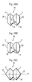
- the small-disc continuous bodies 31 shown in Figure 10A and Figure 10B are formed as that vicinity of the peripheral edges 18 and a connected portion (of the circular plane portions 20) of the small discs 4 are round. Therefore, in comparison with the small-disc continuous body 31 shown in Figure 2, these continuous bodies 31 are stable without looseness, and having high resisting force which makes fixation stronger.
- the small-disc continuous body 31 shown in Figure 10B is rounder, stabler, and stronger in fixation than the small-disc continuous body 31 shown in Figure 10A.
- the small-disc continuous body 31 shown in Figure 10C is formed as that configuration of each end has a raised peak portion 27 conically raised from the circular peripheral edge 18 to an outer side. Therefore, the small-disc continuous body 31 embedded in the retainer 2 rotates around an axis P more easily in comparison with the small-disc continuous body 31 shown in Figure 2.
- the small-disc continuous body 31 may be preferably embedded in the retainer 2 with plastic insert molding. And, the small-disc continuous body 31 may be formed with ceramic.
- the pipe joint has a simple construction, the connected pipe 5 is strongly fixed to the joint main body 1, and connecting work can be conducted easily and swiftly in a small working site thereby.
- the small-disc continuous body 31, composed of two or three small discs 4 holds a stable connection without looseness, and the fixation of the connected pipe 5 becomes stable and strong further.
- biting depth of the small-disc continuous body 31 into the periphery of the connected pipe 5 is always uniform because the small-disc continuous body 31 screws to the parallel female screw portion 6b to complete the fastening, the drawing force becomes stable and reaches for an enough value, and stable connection can be kept.
- connection work can be swiftly and easily completed with a small number of rotations because the tapered female screw portion 6a, the parallel female screw portion 6b, and the male screw portion 7 are double-threaded.
- the small-disc continuous bodies 31 uniformly bite into the whole periphery of the connected pipe 5 for 360°, keep stable connection without looseness, and make further strong fixation.
Landscapes
- Engineering & Computer Science (AREA)
- General Engineering & Computer Science (AREA)
- Mechanical Engineering (AREA)
- Mutual Connection Of Rods And Tubes (AREA)
- Quick-Acting Or Multi-Walled Pipe Joints (AREA)
- Joints With Pressure Members (AREA)
Claims (6)
- Rohrverbindung, umfassend einen Verbindungs-Hauptkörper (1) mit einem konisch zulaufenden Schraubenmutter-Abschnitt (6a) an einem Öffnungsende, sowie einer zylindrischen Halterung (2) mit einem Außengewinde-Abschnitt (7), der in den konisch zulaufenden Schraubenmutter-Abschnitt (6a) eingeschraubt wird und einer Vielzahl von kleinen, scheibenförmigen durchgängigen Körpern (31), von denen jeder aus zwei oder drei kleinen Scheiben (4) für die Rohrfixierung, die entlang eines Gewindes des Außengewinde-Abschnitts (7) in der Halterung (2) derart eingebettet sind, dass ein Teil der kleinen Scheiben (4) zu einer umfänglichen Seite der Halterung (2) hervorsteht und ein anderer Teil der kleinen Scheiben (4) von einer inneren umfänglichen Oberfläche (8) der Halterung (2) hervorsteht, zusammengesetzt ist.
- Rohrverbindung, umfassend einen Verbindungs-Hauptkörper (1) mit einem konisch zulaufenden Schraubenmutter-Abschnitt (6a) und einem parallelen Schraubenmutter-Abschnitt (6b), der fortlaufend von einem offenen Ende ausgeformt ist, sowie eine zylindrische Halterung (2) mit einem Außengewindeabschnitt (7), der in den konisch zulaufenden Schraubenmutter-Abschnitt (6a) und den parallelen Schraubenmutter-Abschnitt (6b) geschraubt ist, und eine Vielzahl von kleinen, scheibenförmigen durchgängigen Körpern (31), von denen jeder aus zwei oder drei kleinen Scheiben (4) für die Rohrverbindung, die entlang eines Gewindes des Außengewindeabschnitts (7) in der Halterung (2) derart eingebettet sind, dass ein Teil der kleinen Scheibe (4) zu einer umfänglichen Seite der Halterung (2) hervorsteht und ein anderer Teil der kleinen Scheibe (4) von einer inneren umfänglichen Oberfläche der Halterung (2) hervorsteht, zusammengesetzt ist.
- Rohrverbindung wie in Anspruch 2 beschrieben, wobei die Halterung (2) in den Verbindungs-Hauptkörper (1) eingeschraubt ist und der kleine, scheibenförmige durchgängige Körper (31) in den parallelen Schraubenmutter-Abschnitt (6b) im zusammengesetzten Zustand der Befestigung eingeschraubt ist.
- Rohrverbindung wie in Anspruch 1 beschrieben, wobei der konisch zulaufende Schraubenmutter-Abschnitt (6a) und der Außengewindeabschnitt (7) zweigängig ausgebildet sind.
- Rohrverbindung wie in Anspruch 2 oder 3 beschrieben, wobei der konisch zulaufende Schraubenmutter-Abschnitt (6a), der parallele Schraubenmutter-Abschnitt (6b) sowie der Außengewindeabschnitt (7) zweigängig sind.
- Rohrverbindung wie in einem der Ansprüche 1 bis 5 beschrieben, wobei zwei kleine, scheibenförmige durchgängige Körper (31) einander um 180°, in einer Richtung der Achse (K) der Rohrverbindung betrachtet und auf einer Ebene, die die Achse (K) unter rechten Winkeln kreuzt, angeordnet sind.
Applications Claiming Priority (2)
| Application Number | Priority Date | Filing Date | Title |
|---|---|---|---|
| JP18230299 | 1999-06-28 | ||
| JP11182302A JP3083517B1 (ja) | 1999-06-28 | 1999-06-28 | 管継手 |
Publications (3)
| Publication Number | Publication Date |
|---|---|
| EP1065423A2 EP1065423A2 (de) | 2001-01-03 |
| EP1065423A3 EP1065423A3 (de) | 2003-01-22 |
| EP1065423B1 true EP1065423B1 (de) | 2005-02-09 |
Family
ID=16115923
Family Applications (1)
| Application Number | Title | Priority Date | Filing Date |
|---|---|---|---|
| EP00111971A Expired - Lifetime EP1065423B1 (de) | 1999-06-28 | 2000-06-16 | Rohrkupplung |
Country Status (9)
| Country | Link |
|---|---|
| US (1) | US6123364A (de) |
| EP (1) | EP1065423B1 (de) |
| JP (1) | JP3083517B1 (de) |
| KR (1) | KR100422279B1 (de) |
| CA (1) | CA2292318C (de) |
| DE (1) | DE60017983T2 (de) |
| ES (1) | ES2233242T3 (de) |
| SG (1) | SG83211A1 (de) |
| TW (1) | TW399133B (de) |
Cited By (4)
| Publication number | Priority date | Publication date | Assignee | Title |
|---|---|---|---|---|
| US8544304B2 (en) | 2007-08-24 | 2013-10-01 | Tenaris Connections Limited | Method for improving fatigue resistance of a threaded joint |
| US9004544B2 (en) | 2009-04-22 | 2015-04-14 | Tenaris Connections Limited | Threaded joint for tubes, pipes and the like |
| US9234612B2 (en) | 2007-06-22 | 2016-01-12 | Tenaris Connections Limited | Threaded joint with energizable seal |
| US9383045B2 (en) | 2007-07-16 | 2016-07-05 | Tenaris Connections Limited | Threaded joint with resilient seal ring |
Families Citing this family (42)
| Publication number | Priority date | Publication date | Assignee | Title |
|---|---|---|---|---|
| JP3083517B1 (ja) * | 1999-06-28 | 2000-09-04 | 東尾メック株式会社 | 管継手 |
| DE60227050D1 (de) | 2001-02-06 | 2008-07-24 | Swagelok Co | Rohrverbindung für rohre aus rostfreiem stahl |
| KR20080091251A (ko) | 2001-02-06 | 2008-10-09 | 스와겔로크 컴패니 | 내부 풀업 표시를 갖는 이음쇠 |
| US7066496B2 (en) | 2001-02-06 | 2006-06-27 | Swagelok Company | Fitting with separable gripping device for pipe and tube |
| US7416225B2 (en) | 2001-02-06 | 2008-08-26 | Swagelok Company | Fitting for metal pipe and tubing |
| US7407196B2 (en) | 2003-08-06 | 2008-08-05 | Swagelok Company | Tube fitting with separable tube gripping device |
| JP4616498B2 (ja) * | 2001-04-04 | 2011-01-19 | 井上スダレ株式会社 | 管継手用リテーナと小円盤連設体の組立方法 |
| AU2003277176A1 (en) * | 2002-09-18 | 2004-04-08 | Swagelok Company | Tube fitting with tube gripping ring and sealant |
| SG148150A1 (en) | 2003-11-03 | 2008-12-31 | Swagelok Co | Fitting for metal pipe and tubing |
| US7497483B2 (en) | 2004-04-22 | 2009-03-03 | Swagelok Company | Fitting for tube and pipe with cartridge |
| TW200602577A (en) | 2004-04-22 | 2006-01-16 | Swagelok Co | Fitting for tube and pipe |
| US7717478B2 (en) * | 2006-08-29 | 2010-05-18 | Hydril Llc | Scalloped wedge threads |
| US8668233B2 (en) * | 2004-12-30 | 2014-03-11 | Hydril Company | Threaded connection with perturbed flanks |
| US20060226652A1 (en) * | 2005-03-24 | 2006-10-12 | Fischer Neal W | Seal and method for a watertight connection in a water service |
| EP2009340B1 (de) | 2007-06-27 | 2010-12-08 | Tenaris Connections Aktiengesellschaft | Gewindeverbindung mit unter Druck setzbarer Dichtung |
| WO2009020900A2 (en) | 2007-08-03 | 2009-02-12 | Swagelok Company | Pull-up by torque ferrule fitting |
| EP2028403B1 (de) | 2007-08-24 | 2011-04-13 | Tenaris Connections Aktiengesellschaft | Gewindeverbindungsstück mit hoher Radiallast und unterschiedlich behandelten Oberflächen |
| EP2096253B1 (de) | 2008-02-29 | 2010-06-16 | Tenaris Connections AG | Gewindeverbindungsstück mit verbesserten elastischen Dichtungsringen |
| DE102008014218A1 (de) * | 2008-03-15 | 2009-09-24 | Oximatec Gmbh | Keramische Dichtungen für Rohrverschraubungen |
| US20110049874A1 (en) * | 2009-08-26 | 2011-03-03 | Charlotte Pipe And Foundry Company | Polymeric pipe fitting and gasket assembly and sealed polymeric pipe apparatus formed therewith |
| EP2325435B2 (de) | 2009-11-24 | 2020-09-30 | Tenaris Connections B.V. | Verschraubung für [ultrahoch] abgedichteten internen und externen Druck |
| EP2372211B1 (de) | 2010-03-26 | 2015-06-03 | Tenaris Connections Ltd. | Dünnwandige Rohrverbindung und Verfahren zum Verbinden eines ersten Rohres mit einem zweiten Rohr |
| KR101181208B1 (ko) | 2010-07-20 | 2012-09-07 | 세창주철공업 주식회사 | 회전손잡이가 구비된 관 연결 어셈블리 |
| US9136680B2 (en) * | 2010-07-26 | 2015-09-15 | Mikeal Roberts | Protective fitting |
| US9163296B2 (en) | 2011-01-25 | 2015-10-20 | Tenaris Coiled Tubes, Llc | Coiled tube with varying mechanical properties for superior performance and methods to produce the same by a continuous heat treatment |
| BR112015016765A2 (pt) | 2013-01-11 | 2017-07-11 | Tenaris Connections Ltd | conexão de tubos de perfuração, tubo de perfuração correspondente e método para montar tubos de perfuração |
| US9803256B2 (en) | 2013-03-14 | 2017-10-31 | Tenaris Coiled Tubes, Llc | High performance material for coiled tubing applications and the method of producing the same |
| EP2789701A1 (de) | 2013-04-08 | 2014-10-15 | DALMINE S.p.A. | Hochfeste mittelwandige vergütete und nahtlose Stahlrohre und entsprechendes Verfahren zur Herstellung der Stahlrohre |
| EP2789700A1 (de) | 2013-04-08 | 2014-10-15 | DALMINE S.p.A. | Dickwandige vergütete und nahtlose Stahlrohre und entsprechendes Verfahren zur Herstellung der Stahlrohre |
| KR102197204B1 (ko) | 2013-06-25 | 2021-01-04 | 테나리스 커넥션즈 비.브이. | 고크롬 내열철강 |
| KR102398921B1 (ko) | 2014-05-09 | 2022-05-16 | 스와겔로크 컴패니 | 조립을 촉진시키도록 적응된 부품을 구비한 도관 피팅 |
| WO2015187958A1 (en) | 2014-06-04 | 2015-12-10 | Parker-Hannifin Corporation | Compression fitting with torque nut |
| DE102014217410B4 (de) | 2014-09-01 | 2022-01-20 | Ford Global Technologies, Llc | Fluidleitende Verbindungsanordnung sowie Klemmring |
| CN104454841B (zh) * | 2014-12-12 | 2016-06-22 | 中山市思锐摄影器材工业有限公司 | 一种防水伸缩管结构 |
| US20160305192A1 (en) | 2015-04-14 | 2016-10-20 | Tenaris Connections Limited | Ultra-fine grained steels having corrosion-fatigue resistance |
| CN107850244B (zh) * | 2015-08-03 | 2019-09-03 | 崔熙文 | 管连接用顶端接合环 |
| WO2017165162A1 (en) | 2016-03-23 | 2017-09-28 | Swagelok Company | Conduit fitting with stroke resisting features |
| US11124852B2 (en) | 2016-08-12 | 2021-09-21 | Tenaris Coiled Tubes, Llc | Method and system for manufacturing coiled tubing |
| KR101941424B1 (ko) | 2016-08-26 | 2019-01-23 | 천재영 | Z자형 실링재를 이용한 배관 이음체 |
| US10434554B2 (en) | 2017-01-17 | 2019-10-08 | Forum Us, Inc. | Method of manufacturing a coiled tubing string |
| TWI636834B (zh) * | 2017-11-22 | 2018-10-01 | 劉守德 | Metal pipe joint assembly |
| CN111706584A (zh) * | 2020-05-09 | 2020-09-25 | 浙江捷昌线性驱动科技股份有限公司 | 一种升降立柱间隙片安装组件和升降立柱 |
Family Cites Families (18)
| Publication number | Priority date | Publication date | Assignee | Title |
|---|---|---|---|---|
| US1711995A (en) * | 1927-11-14 | 1929-05-07 | Frederic W Erickson | Threadless conduit fitting |
| US2127284A (en) * | 1937-01-18 | 1938-08-16 | William S Board | Pipe coupling |
| US2346051A (en) * | 1942-06-16 | 1944-04-04 | Seamark Lewis Mervyn Cecil | Pipe and other coupling |
| US3384393A (en) * | 1965-04-19 | 1968-05-21 | Myers Electric Products Inc | Conduit connector for junction boxes |
| DE1958205A1 (de) * | 1969-11-19 | 1971-05-27 | Georg Seiler | Schubsicherung bei Muffenverbindungen von Rohren |
| US4005884A (en) * | 1972-06-21 | 1977-02-01 | Mordechai Drori | Pipe coupling |
| JPS552314Y2 (de) * | 1974-03-13 | 1980-01-21 | ||
| US4022499A (en) * | 1975-04-14 | 1977-05-10 | Aeroquip Corporation | Tube retaining compression fitting |
| JPS52100222U (de) * | 1976-01-28 | 1977-07-29 | ||
| US4358215A (en) * | 1980-10-20 | 1982-11-09 | Rivin Evgeny I | Key connection |
| US4540201A (en) * | 1983-05-16 | 1985-09-10 | Tuthill Corporation | Tube connector |
| JPS6441787U (de) * | 1987-09-07 | 1989-03-13 | ||
| MX172184B (es) * | 1988-02-01 | 1993-12-07 | Lothar Elsner | Conexion apretadora para tubos |
| US5299838A (en) * | 1992-06-25 | 1994-04-05 | Yang Ming Tung | Pipe connection with clip assembly having pivoting plates |
| DE4234441C2 (de) * | 1992-10-13 | 2001-06-07 | Voss Armaturen | Lösbarer Steckverbinder für Kunststoffrohrleitungen |
| US5522624A (en) * | 1994-07-01 | 1996-06-04 | Seal-Plug, Inc. | Pipe joint and seal |
| KR960037958U (ko) * | 1995-05-24 | 1996-12-18 | 관 이음쇠 | |
| JP3083517B1 (ja) * | 1999-06-28 | 2000-09-04 | 東尾メック株式会社 | 管継手 |
-
1999
- 1999-06-28 JP JP11182302A patent/JP3083517B1/ja not_active Expired - Lifetime
- 1999-07-27 TW TW088112835A patent/TW399133B/zh not_active IP Right Cessation
- 1999-12-06 CA CA002292318A patent/CA2292318C/en not_active Expired - Fee Related
- 1999-12-15 US US09/461,007 patent/US6123364A/en not_active Expired - Lifetime
-
2000
- 2000-06-16 EP EP00111971A patent/EP1065423B1/de not_active Expired - Lifetime
- 2000-06-16 DE DE60017983T patent/DE60017983T2/de not_active Expired - Lifetime
- 2000-06-16 ES ES00111971T patent/ES2233242T3/es not_active Expired - Lifetime
- 2000-06-19 KR KR10-2000-0033574A patent/KR100422279B1/ko not_active Expired - Fee Related
- 2000-06-22 SG SG200003519A patent/SG83211A1/en unknown
Cited By (4)
| Publication number | Priority date | Publication date | Assignee | Title |
|---|---|---|---|---|
| US9234612B2 (en) | 2007-06-22 | 2016-01-12 | Tenaris Connections Limited | Threaded joint with energizable seal |
| US9383045B2 (en) | 2007-07-16 | 2016-07-05 | Tenaris Connections Limited | Threaded joint with resilient seal ring |
| US8544304B2 (en) | 2007-08-24 | 2013-10-01 | Tenaris Connections Limited | Method for improving fatigue resistance of a threaded joint |
| US9004544B2 (en) | 2009-04-22 | 2015-04-14 | Tenaris Connections Limited | Threaded joint for tubes, pipes and the like |
Also Published As
| Publication number | Publication date |
|---|---|
| KR100422279B1 (ko) | 2004-03-10 |
| DE60017983D1 (de) | 2005-03-17 |
| DE60017983T2 (de) | 2005-12-29 |
| JP3083517B1 (ja) | 2000-09-04 |
| JP2001012666A (ja) | 2001-01-16 |
| HK1033350A1 (en) | 2001-08-24 |
| TW399133B (en) | 2000-07-21 |
| CA2292318C (en) | 2005-08-23 |
| CA2292318A1 (en) | 2000-12-28 |
| KR20010007433A (ko) | 2001-01-26 |
| EP1065423A2 (de) | 2001-01-03 |
| US6123364A (en) | 2000-09-26 |
| EP1065423A3 (de) | 2003-01-22 |
| SG83211A1 (en) | 2001-09-18 |
| ES2233242T3 (es) | 2005-06-16 |
Similar Documents
| Publication | Publication Date | Title |
|---|---|---|
| US6123364A (en) | Pipe joint | |
| EP1995506A2 (de) | Rohrverbindung | |
| CA2483173C (en) | Pipe joint | |
| US5681058A (en) | Assembly for joining a pipe to a pipe fitting | |
| US12396827B2 (en) | Prosthetic dental screw implant, tightening tool and coupling system between the two | |
| JP3497158B1 (ja) | 管接続装置 | |
| US6641178B2 (en) | Jointing system for pipes | |
| JP3600764B2 (ja) | 管継手 | |
| EP2381152A1 (de) | Verzahnte rohrverbindungsstruktur, ventil, verzahnte rohrverbindung und kühlvorrichtung | |
| HK1033350B (en) | Pipe joint | |
| JP2007198543A (ja) | 管継手 | |
| EP2156913A1 (de) | Spannfutter | |
| JP3122385B2 (ja) | 管継手 | |
| KR960006180B1 (ko) | 유체 기밀 이음용 파이프 조인트 | |
| JP2997671B1 (ja) | 継 手 | |
| US20080290653A1 (en) | Pipe Coupling | |
| JP2007198542A (ja) | 管継手 | |
| JP2000046282A (ja) | ロックリング及びその製造方法 | |
| US4755079A (en) | Connection structure having sealing function for spigot member | |
| JPH0738724U (ja) | タッピングネジ | |
| JP4284086B2 (ja) | 合成樹脂製継手 | |
| JP3568906B2 (ja) | 管継手構造 | |
| JP2002295752A (ja) | 管継手 | |
| KR200187818Y1 (ko) | 배관연결장치 | |
| JP2004052839A (ja) | 可撓性樹脂管用継手 |
Legal Events
| Date | Code | Title | Description |
|---|---|---|---|
| PUAI | Public reference made under article 153(3) epc to a published international application that has entered the european phase |
Free format text: ORIGINAL CODE: 0009012 |
|
| AK | Designated contracting states |
Kind code of ref document: A2 Designated state(s): AT BE CH CY DE DK ES FI FR GB GR IE IT LI LU MC NL PT SE |
|
| AX | Request for extension of the european patent |
Free format text: AL;LT;LV;MK;RO;SI |
|
| PUAL | Search report despatched |
Free format text: ORIGINAL CODE: 0009013 |
|
| AK | Designated contracting states |
Kind code of ref document: A3 Designated state(s): AT BE CH CY DE DK ES FI FR GB GR IE IT LI LU MC NL PT SE |
|
| AX | Request for extension of the european patent |
Free format text: AL;LT;LV;MK;RO;SI |
|
| 17P | Request for examination filed |
Effective date: 20030324 |
|
| AKX | Designation fees paid |
Designated state(s): DE ES FR GB IT NL |
|
| GRAP | Despatch of communication of intention to grant a patent |
Free format text: ORIGINAL CODE: EPIDOSNIGR1 |
|
| GRAS | Grant fee paid |
Free format text: ORIGINAL CODE: EPIDOSNIGR3 |
|
| GRAA | (expected) grant |
Free format text: ORIGINAL CODE: 0009210 |
|
| AK | Designated contracting states |
Kind code of ref document: B1 Designated state(s): DE ES FR GB IT NL |
|
| REG | Reference to a national code |
Ref country code: GB Ref legal event code: FG4D |
|
| REG | Reference to a national code |
Ref country code: IE Ref legal event code: FG4D |
|
| REF | Corresponds to: |
Ref document number: 60017983 Country of ref document: DE Date of ref document: 20050317 Kind code of ref document: P |
|
| REG | Reference to a national code |
Ref country code: ES Ref legal event code: FG2A Ref document number: 2233242 Country of ref document: ES Kind code of ref document: T3 |
|
| REG | Reference to a national code |
Ref country code: HK Ref legal event code: GR Ref document number: 1033350 Country of ref document: HK |
|
| PLBE | No opposition filed within time limit |
Free format text: ORIGINAL CODE: 0009261 |
|
| STAA | Information on the status of an ep patent application or granted ep patent |
Free format text: STATUS: NO OPPOSITION FILED WITHIN TIME LIMIT |
|
| 26N | No opposition filed |
Effective date: 20051110 |
|
| ET | Fr: translation filed | ||
| PGFP | Annual fee paid to national office [announced via postgrant information from national office to epo] |
Ref country code: ES Payment date: 20120531 Year of fee payment: 13 |
|
| PGFP | Annual fee paid to national office [announced via postgrant information from national office to epo] |
Ref country code: DE Payment date: 20130620 Year of fee payment: 14 Ref country code: GB Payment date: 20130603 Year of fee payment: 14 |
|
| PGFP | Annual fee paid to national office [announced via postgrant information from national office to epo] |
Ref country code: NL Payment date: 20130606 Year of fee payment: 14 Ref country code: IT Payment date: 20130606 Year of fee payment: 14 Ref country code: FR Payment date: 20130702 Year of fee payment: 14 |
|
| REG | Reference to a national code |
Ref country code: DE Ref legal event code: R119 Ref document number: 60017983 Country of ref document: DE |
|
| REG | Reference to a national code |
Ref country code: NL Ref legal event code: V1 Effective date: 20150101 |
|
| GBPC | Gb: european patent ceased through non-payment of renewal fee |
Effective date: 20140616 |
|
| REG | Reference to a national code |
Ref country code: DE Ref legal event code: R119 Ref document number: 60017983 Country of ref document: DE Effective date: 20150101 |
|
| REG | Reference to a national code |
Ref country code: FR Ref legal event code: ST Effective date: 20150227 |
|
| PG25 | Lapsed in a contracting state [announced via postgrant information from national office to epo] |
Ref country code: NL Free format text: LAPSE BECAUSE OF NON-PAYMENT OF DUE FEES Effective date: 20150101 |
|
| PG25 | Lapsed in a contracting state [announced via postgrant information from national office to epo] |
Ref country code: IT Free format text: LAPSE BECAUSE OF NON-PAYMENT OF DUE FEES Effective date: 20140616 Ref country code: DE Free format text: LAPSE BECAUSE OF NON-PAYMENT OF DUE FEES Effective date: 20150101 |
|
| PG25 | Lapsed in a contracting state [announced via postgrant information from national office to epo] |
Ref country code: FR Free format text: LAPSE BECAUSE OF NON-PAYMENT OF DUE FEES Effective date: 20140630 Ref country code: GB Free format text: LAPSE BECAUSE OF NON-PAYMENT OF DUE FEES Effective date: 20140616 |
|
| REG | Reference to a national code |
Ref country code: ES Ref legal event code: FD2A Effective date: 20150730 |
|
| PG25 | Lapsed in a contracting state [announced via postgrant information from national office to epo] |
Ref country code: ES Free format text: LAPSE BECAUSE OF NON-PAYMENT OF DUE FEES Effective date: 20140617 |